Raspberry Pi Pico W with LoRa SX1278 for Sensor Monitoring
Last Updated on September 21, 2024 by Engr. Shahzada Fahad
Table of Contents
Raspberry Pi Pico W with LoRa:
Raspberry Pi Pico W with LoRa SX1278 for Sensor Monitoring– In this tutorial, you will learn how to use Long Range LoRa SX1278 Transceiver modules with Raspberry Pi Pico and Raspberry Pi Pico W. If you want you can also use the same Raspberry Pi Pico boards since they have got the same pins layout. But, the reason I am using these two different versions of the Raspberry Pi Pico boards is; because in my next tutorial I will make an IoT gateway using LoRa and Raspberry Pi Pico W.
You know just like the Arduino, ESP8266, STM32, ESP32, etc you can also program the Raspberry Pi Pico and Raspberry Pi Pico W using Arduino IDE. So, if you want to learn how to get started with Raspberry Pi Pico and Arduino IDE then you should read my getting started article on the Raspberry Pi Pico W and Adafruit IO.
Anyway, for now, as a beginner, you should only focus on how to wirelessly send sensor data from a transmitter Raspberry Pi Pico to a receiver Raspberry Pi Pico W using LoRa Transceiver modules. Because once you learn how to wirelessly send data from Raspberry Pi Pico to Raspberry Pi Pico W; then building an IoT Gateway is a piece of cake as Raspberry Pi Pico W can be connected with different IoT platforms, and by the way I have already demonstrated this in my getting started tutorial on the Raspberry Pi Pico W and Adafruit Io.
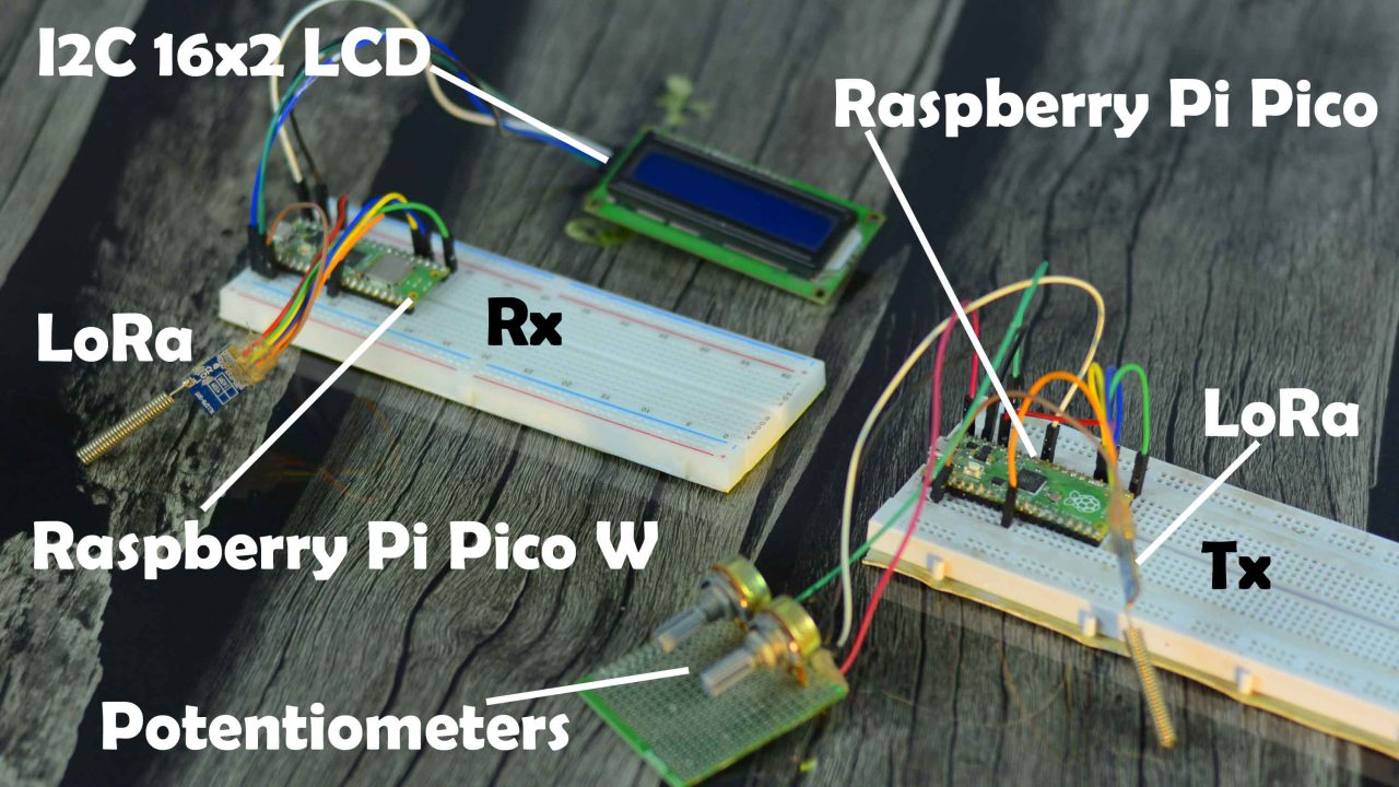
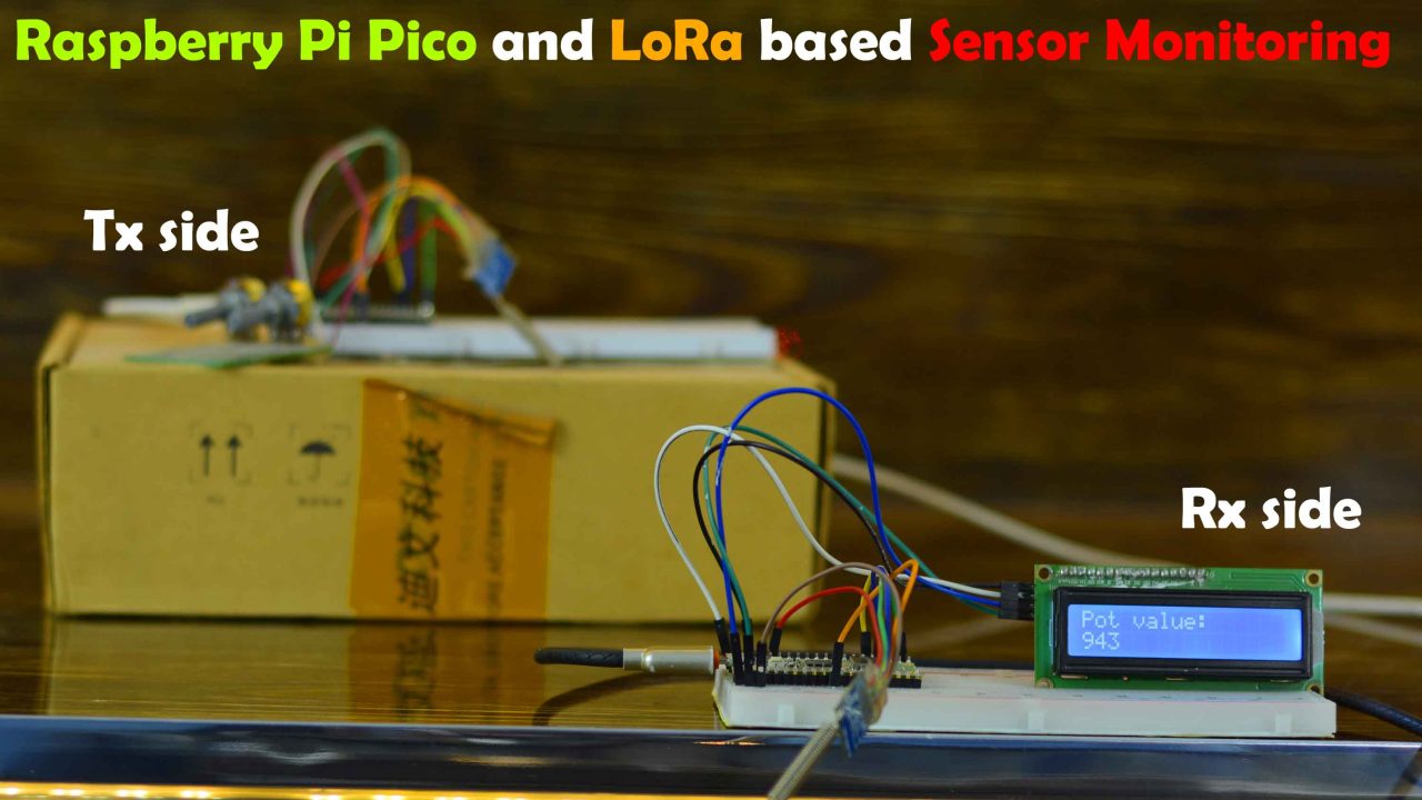
Anyway, here is a prototype model of my Raspberry Pi Pico and LoRa based Long Range sensor monitoring system. I have connected everything as per the circuit diagrams which I will explain in a minute.
On the right side, is the transmitter based on the Raspberry Pi Pico, along which a Potentiometer and SX1278 LoRa transceiver moduleare connected. The Raspberry Pi Pico reads the Potentiometer which I am using as a sensor and sends the Potentiometer readings to the remote side receiver using the LoRa.
And on the left side, is the receiver based on the Raspberry Pi Pico W. It has been connected with ani2c-supported 16×2 LCD and an SX1278 LoRa transceiver module. If you want you can also use an i2c-supported SSD1306 Oled display module, I have already used it in so many videos.The Raspberry Pi Pico W takes the data from the LoRa and prints it on the 16×2 LCD. Now, let’s go ahead and start our practical demonstration.
Using 5V adaptors, I powered up the Transmitter and Receiver. You can see the Potentiometer value on the 16×2 LCD. Now, I am going to rotate the knob of the potentiometer on the receiver side.
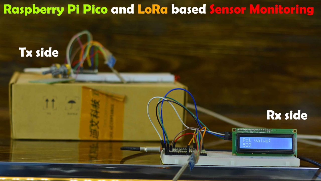
After rotating the knob of the potentiometer, the value changed from 529 to 943. For the practical demonstration, you can watch the video tutorial available on my YouTube channel Electronic Clinic or you can click on the link given at the end of this article.
I am sure by now, you might have got an idea of how does this system work. So, without any further delay let’s get started!!!
Amazon Links:
Sx1278 LoRa Transceiver modules
Other Tools and Components:
Super Starter kit for Beginners
PCB small portable drill machines
*Please Note: These are affiliate links. I may make a commission if you buy the components through these links. I would appreciate your support in this way!
Lora SX1278 Module:
The SX1276/77/78/79 transceivers feature the LoRa TM long range modem that provides ultra-long range spread spectrum communication and high interference immunity whilst minimizing current consumption.
Using Semtech’s patented LoRa modulation technique SX1276/77/78/79 can achieve a sensitivity of over -148dBm using a low cost crystal and bill of materials. The high sensitivity combined with the integrated +20 dBm power amplifier yields industry leading link budget making it optimal for any application requiring range or robustness.
LoRa also provides significant advantages in both blocking and selectivity over conventional modulation techniques, solving the traditional design compromise between range, interference immunity and energy consumption.
These devices also support high performance (G)FSK modes for systems including WMBus, IEEE802.15.4g. The SX1276/77/78/79 deliver exceptional phase noise, selectivity, receiver linearity and IIP3 for significantly lower current consumption than competing devices.
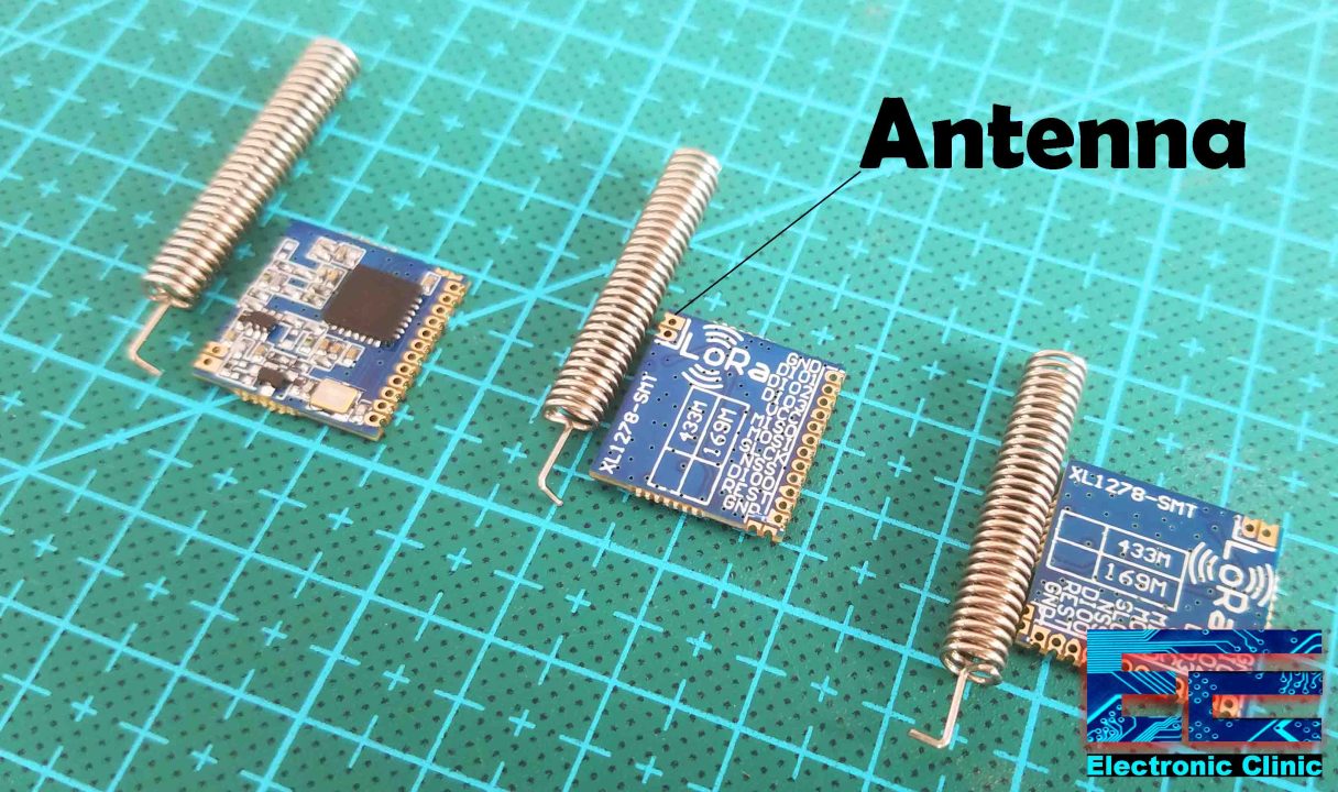
I have got these three LoRa SX1278 Modules, LoRa (Long-Range) is digital wireless data communication IoT technology. LoRa transmits over license-free megahertz radio frequency bands: 169 MHz, 433 MHz (Asia), 868 MHz (Europe) and 915 MHz (North America). LoRa enables very-long-range wireless data transmission. The type of the LoRa modules I am using supports 433MHz. Each LoRa module is also provided with an Antenna which we will need to solder to the boards to increase the wireless communication range.
The supply voltage is 1.8 to 3.7 volts, so it can be used with 3.3 Volts and 5 volts compatible controller boards without any problem. 3.3V compatible boards e.g. ESP8266, ESP32, Raspberry Pi Pico, etc. The operational temperature range is -40 Celsius to +85 Celsius.
It has a total of 12 via’s or holes which are clearly labeled and out of which we will be using only VCC, MISO, MOSI, SLCK, NSS, and GND.
As a beginner you may get scared when you first look at these LoRa modules which has holes as they are very close to each other because you cannot solder regular male or female headers. But no worries at all, you can simply start by soldering jumper wires, which of course will need some soldering practice.
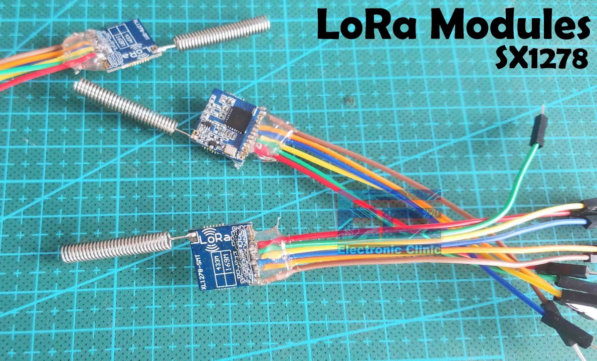
As you can see I soldered the jumpers wires and the antennas. Next, I checked the short circuits using a digital Multimeter, and then to secure the wires I applied the silicon, this will help to keep the wires in place and will also protect the wires from getting disconnected.
LoRa Applications:
When it comes to the applications, you have almost infinite ways of controlling and monitoring things including,
Automated Meter Reading.
Home and Building Automation
Wireless Alarm and Security System
Industrial Monitoring and Control
Long range Irrigation Systems and so on…
Raspberry Pi Pico Tx Circuit:
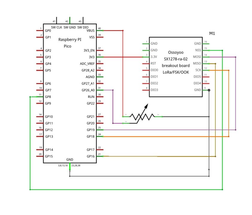
3.3V and GND pins of the LoRa SX1278 are connected with the Raspberry Pi Pico 3.3V and GND pins. While the NSS, MISO, SCK, and MOSI pins of the LoRa SX1278 Transceiver module are connected with the Raspberry Pi Pico GPIO pins 8, 16, 18, and 19.
The potentiometer is connected with the GP26_A0 which is an analog pin.
Raspberry Pi Pico W Rx Circuit:
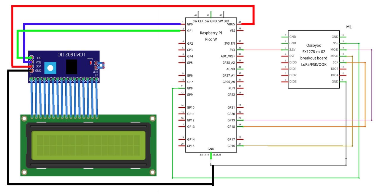
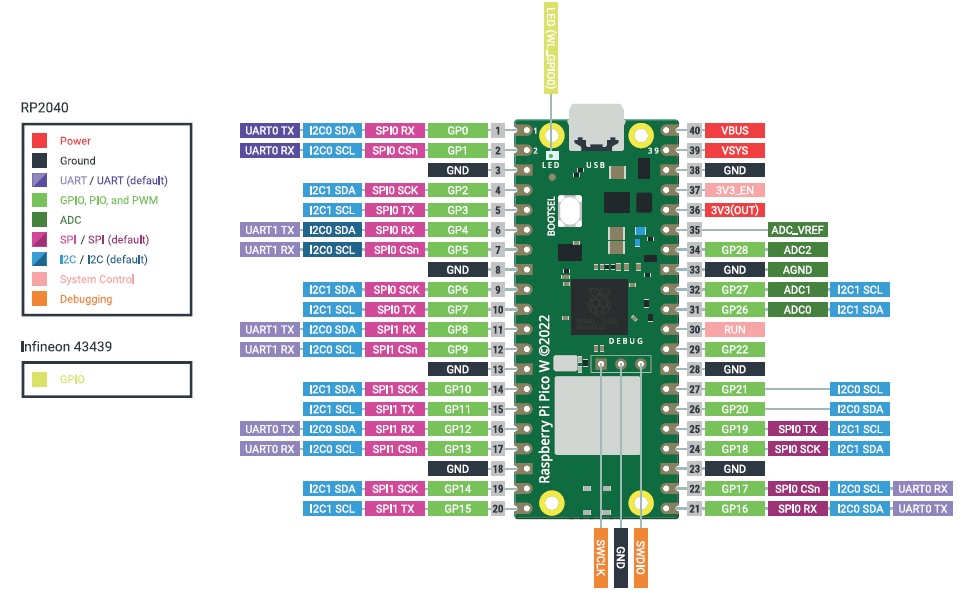
This is the receiver side circuit diagram. You can see the LoRa SX1278 connection with the Raspberry Pi Pico W remains exactly the same. The VCC pin of the I2C supported 16×2 LCD is connected with the VBUS which is the 5V pin. And obviously the grounds are connected together. The SDA and SCL pins of the I2C supported 16×2 LCD are connected with the GP0 and GP1. As per the Pins layout diagram GP0 is the SDA and GP1 is the SCL.
So, that’s all about the receiver side circuit diagram. Now, let’s go ahead and take a look at the Transmitter and receiver side programming.
Required Libraries:
Download the liquidCrystal_I2C and unzip the folder. Open the folder and copy the .h and .cpp files and paste them in the receiver side programming folder. The receiver side main code and these .h and .cpp files are need to inside the same folder. If you find it hard to understand then I highly recommend you should watch my video tutorial. Link is given at the end of this article.
Raspberry Pi Pico LoRa Tx Code:
|
1 2 3 4 5 6 7 8 9 10 11 12 13 14 15 16 17 18 19 20 21 22 23 24 25 26 27 28 29 30 31 32 33 34 35 36 37 38 39 40 41 42 43 44 45 46 47 48 49 50 51 52 53 54 55 56 57 58 59 60 61 62 63 64 65 66 67 68 69 70 71 72 73 |
/* Raspberry pi pico transmitter https://www.electroniclinic.com/ */ #include <SPI.h> // include libraries #include <LoRa.h> #define nss 8 #define rst 9 #define dio0 7 byte MasterNode = 0xFF; byte Node2 = 0xCC; int pot2=26; String SenderNode = ""; String outgoing; // outgoing message String message1; String message2; byte msgCount = 0; // count of outgoing messages // Tracks the time since last event fired unsigned long previousMillis=0; unsigned long int previoussecs = 0; unsigned long int currentsecs = 0; unsigned long currentMillis = 0; int Secs = 0; long lastSendTime = 0; // last send time int interval = 20; // interval between sends void setup() { Serial.begin(9600); // initialize serial pinMode(pot2,INPUT); LoRa.setPins(nss, rst, dio0); if (!LoRa.begin(433E6)) { // initialize ratio at 915 MHz Serial.println("LoRa init failed. Check your connections."); while (true); // if failed, do nothing } Serial.println("LoRa init succeeded."); } void loop() { if (millis() - lastSendTime > interval) { int sensor2; sensor2 = analogRead(pot2); Serial.println(sensor2); message2=message2 + sensor2 +","; sendMessage(message2,MasterNode,Node2); delay(50); //Serial.println("Sending " + message); lastSendTime = millis(); // timestamp the message // interval = random(50); message1=""; message2 = ""; } } void sendMessage(String outgoing, byte MasterNode, byte otherNode) { LoRa.beginPacket(); // start packet LoRa.write(otherNode); // add destination address LoRa.write(MasterNode); // add sender address LoRa.write(msgCount); // add message ID LoRa.write(outgoing.length()); // add payload length LoRa.print(outgoing); // add payload LoRa.endPacket(); // finish packet and send it msgCount++; // increment message ID } |
If you have read my previous articles on the Arduino and Lora then I am sure you should have noticed that I am using the same libraries and the same program. Only the pin numbers are different. So, it means you can convert all my Arduino and LoRa based projects into Raspberry Pi Pico and Lora based projects. Now, let’s take a look at the receiver side programming.
Raspberry Pi Pico W LoRa Rx Code:
|
1 2 3 4 5 6 7 8 9 10 11 12 13 14 15 16 17 18 19 20 21 22 23 24 25 26 27 28 29 30 31 32 33 34 35 36 37 38 39 40 41 42 43 44 45 46 47 48 49 50 51 52 53 54 55 56 57 58 59 60 61 62 63 64 65 66 67 68 69 70 71 72 73 74 75 76 77 78 79 80 81 82 83 84 85 86 87 88 89 90 91 92 93 94 95 96 97 98 99 100 101 102 103 104 |
/* Raspberry pi pico w receiver https://www.electroniclinic.com/ */ #include <SPI.h> // include libraries #include <LoRa.h> #include "LiquidCrystal_I2C.h" #include <Wire.h> #define PCF8574 0x27 #define PCF8574A 0x3F TwoWire Wire_00(i2c0, 0,1); // SDA, SCL LiquidCrystal_I2C lcd(&Wire_00, PCF8574, 16, 2); String outgoing; // outgoing message byte msgCount = 0; // count of outgoing messages byte MasterNode = 0xFF; byte Node2 = 0xCC; #define nss 8 #define rst 9 #define dio0 7 void setup() { Serial.begin(115200); Wire_00.begin(); Wire_00.setClock(100000); // 100kHz lcd.begin(); lcd.backlight(); //lcd.print("Pot Value"); LoRa.setPins(nss, rst, dio0); if (!LoRa.begin(433E6)) { // initialize ratio at 915 MHz Serial.println("LoRa init failed. Check your connections."); while (true); // if failed, do nothing } Serial.println("LoRa init succeeded."); } void loop() { // parse for a packet, and call onReceive with the result: onReceive(LoRa.parsePacket()); } void onReceive(int packetSize) { if (packetSize == 0) return; // if there's no packet, return // read packet header bytes: int recipient = LoRa.read(); // recipient address byte sender = LoRa.read(); // sender address byte incomingMsgId = LoRa.read(); // incoming msg ID byte incomingLength = LoRa.read(); // incoming msg length String incoming = ""; while (LoRa.available()) { incoming += (char)LoRa.read(); } if (incomingLength != incoming.length()) { // check length for error // Serial.println("error: message length does not match length"); ; return; // skip rest of function } // if the recipient isn't this device or broadcast, if (recipient != Node2 && recipient != MasterNode) { //Serial.println("This message is not for me."); ; return; // skip rest of function } // Serial.println(incoming); // int Val = incoming.toInt(); String q = getValue(incoming, ',', 0); int Val = q.toInt(); lcd.clear(); lcd.print("Pot value:"); lcd.setCursor(0,1); lcd.print(Val); Serial.println(Val); incoming=""; delay(1000); } String getValue(String data, char separator, int index) { int found = 0; int strIndex[] = { 0, -1 }; int maxIndex = data.length() - 1; for (int i = 0; i <= maxIndex && found <= index; i++) { if (data.charAt(i) == separator || i == maxIndex) { found++; strIndex[0] = strIndex[1] + 1; strIndex[1] = (i == maxIndex) ? i+1 : i; } } return found > index ? data.substring(strIndex[0], strIndex[1]) : ""; } |
Even on the receiver side, I am using the same exact program which I have been using with the Arduino. The only modification is the addition of the i2c supported 16×2 LCD library. The i2c supported 16×2 library I have been using with the Arduino doesn’t work with the Raspberry Pi Pico, so, after searching for hours, finally, I found this library that works with the Raspberry Pi Pico. Make sure you save these .h and .cpp files in the same folder with this main programming file. So, that’s all for now.
Watch Video Tutorial:

Discover more from Electronic Clinic
Subscribe to get the latest posts sent to your email.