XIAO ESP32C3 Bluetooth Tutorial, Range test, and Home Automation
Last Updated on September 21, 2024 by Engr. Shahzada Fahad
Table of Contents
XIAO ESP32C3 Bluetooth:
This is the Smallest ESP32C3 WiFi + Bluetooth development board. In my previous tutorial, I explained its technical specifications, it’s pinout, board installation using Arduino IDE, and I also practically demonstrated how to control an LED and how to make an IoT based temperature and Humidity monitoring system using the Adafruit IO and the ESP32C3 onboard WiFi. So, if you are just starting with the XIAO ESP32C3 then I highly recommend, you should read my getting started article on the XIAO ESP32C3 WiFi + Bluetooth Development Board.
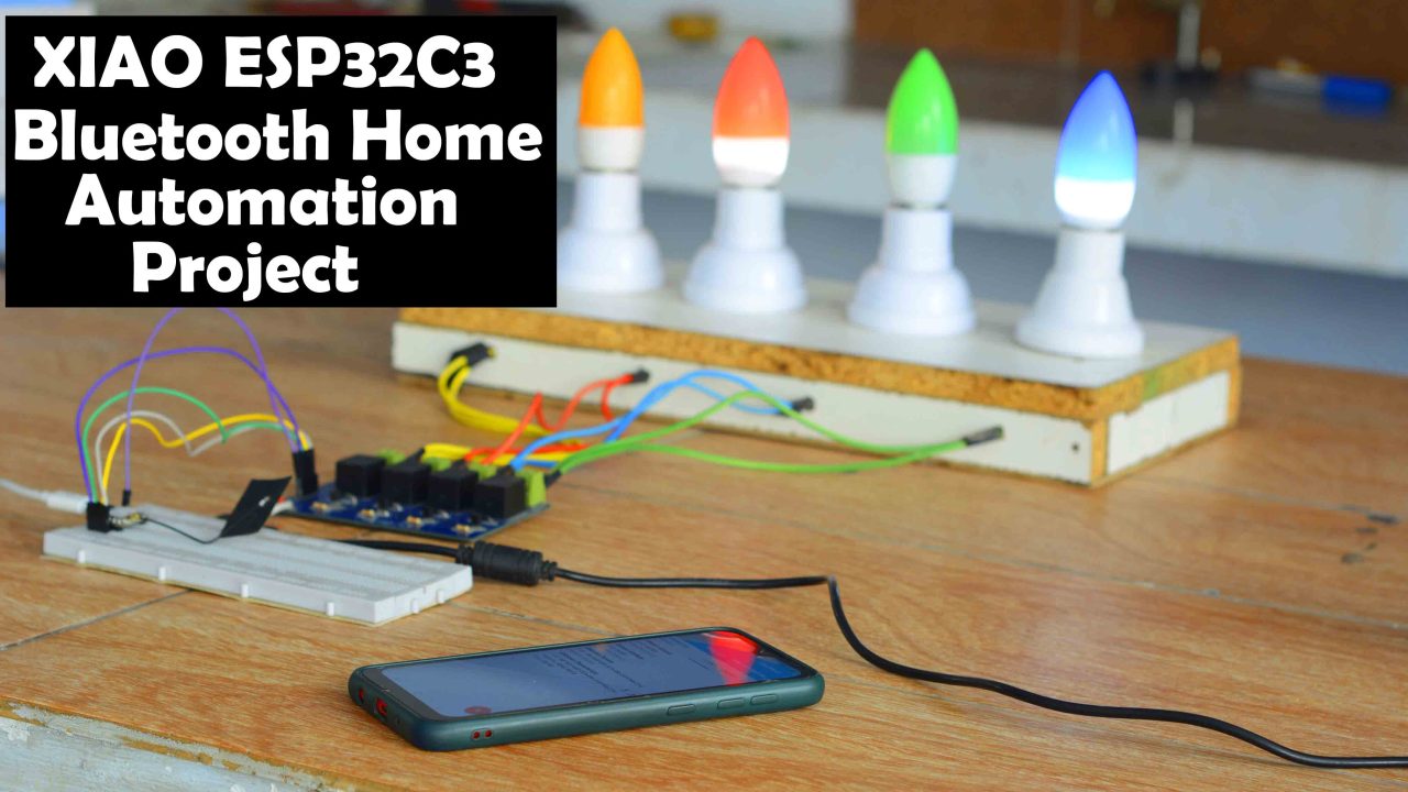
Anyway, in today’s article, you will learn how to use XIAO ESP32C3 onboard Bluetooth with an Android application for controlling electrical appliances.
Besides this, I will also do a range test. And we will see if the XIAO ESP32C3 onboard Low Energy Bluetooth 5 and the WiFi/Bluetooth Antenna really increases the signal strength. The manufacturer claims that it has a maximum communication range of +100 meters. If it’s true then it means I can control my home appliances and other electrical loads even from outside; 100 meters is such a long distance. I am still going to be quite happy even if it gives me around 40 to 50 meters.

HC05 Bluetooth module never gave me such a long distance. And look at the size difference XIAO ESP32C3 is much smaller than the HC05 Bluetooth module. So, using the smallest ESP32C3 development board we can really reduce the project size and cost. Anyway, first I am going to share with you the final test results and afterward, I will explain everything else.

For demonstration purposes, I have connected 4 bulbs, which are connected to 4 relays. Besides lights, you can use any other 110/220Vac loads or use any other DC type loads.
If you want to use 110/220Vac supply, you must not forget to use protective gloves, because 110/220Vac can prove fatal. So, as far as possible you must ensure the presence of a friend or any companion while carrying on work on such projects. When the AC supply is ON, do not touch the relay module.
I have already paired the ESP32C3 onboard Bluetooth with my cell phone. For sending the control commands I am going to use nRF Connect application, which is available on Playstore. This application lets you scan, discover, and debug your Bluetooth Low Energy devices. So, let’s go ahead and open this application.
Enable the Bluetooth.
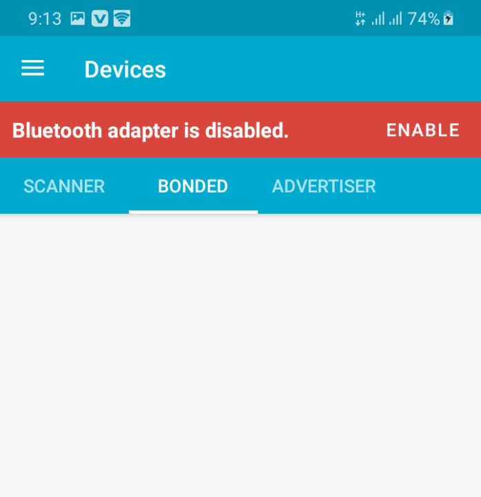
Click on BONDED.
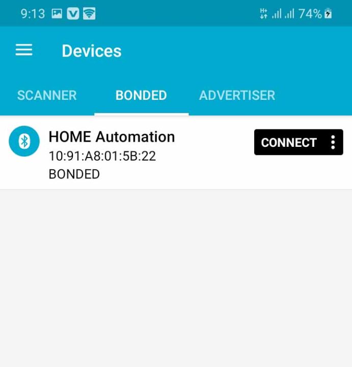
You can see the name Home Automation, I defined it in the programming. If you want you can change this name. Anyway, click on the CONNECT button. And then click on the Unknown Service.
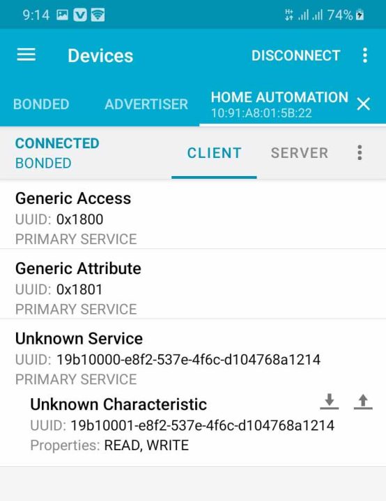
You can see the up and down arrows. Use the up arrow to send the control commands. Now, the cell phone App is ready and we can start sending the control commands. Simply click on the up arrow.
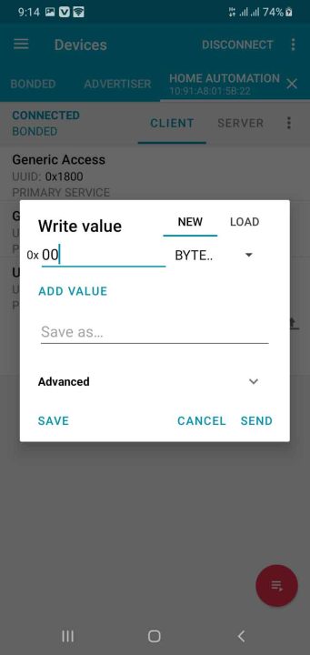
Write the command and press on the SEND button.
| 00 | Turn off light 1 |
| 01 | Turn on light 1 |
| 02 | Turn off light 2 |
| 03 | Turn on light 2 |
| 04 | Turn off light 3 |
| 05 | Turn on light 3 |
| 06 | Turn off light 4 |
| 07 | Turn on light 4 |
Here is a list of all the commands I am using to control all the 4 Bulbs. All these commands are defined in the programming, so if you want you can change these commands.
Its working great, I am able to turn ON and turn OFF these bulbs.
ESP32C3 Bluetooth Range Test:
Now, I am going to test the ESP32C3 Bluetooth communication range. My cousin is going to send the control signals from different locations. Right now my cousin is 26 meters away from the ESP32C3. I measured the distance using Google Earth.
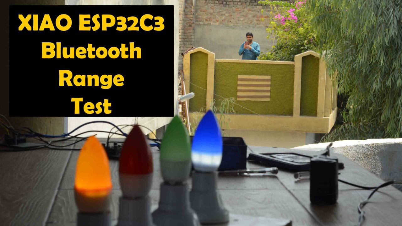
At 26 meters its working great. For me, 26 meters is more than enough to control my Home appliances and other devices.
For this next test, I sent my cousin outside the house and now the distance between the cell phone and the XIAO ESP32C3 Onboard Bluetooth is 40 meters. I confirmed the distance on Google Maps. We were able to control the lights from 40 meters away. For practical demonstration watch video tutorial on my YouTube channel Electronic Clinic.
For the 3rd test, I told my cousin to control the same lights from his house which is around 80 meters away. But he wasn’t able to connect his cell phone with the XIAO ESP32C3 onboard Bluetooth. This is because of the obstacles like concrete walls. I am sure in an open area it’s going to hit 100+ meters. We also controlled the same lights from the ground floor and from other locations in my house. As per my needs and requirements, the XIAO ESP32C3 WiFi + Bluetooth development board is simply amazing.
Now, I am going to explain the circuit diagram and programming. So, without any further delay, let’s get started!!!
Amazon Links:
*Disclosure: These are affiliate links. As an Amazon Associate I earn from qualifying purchases.
XIAO ESP32C3 Home Automation:
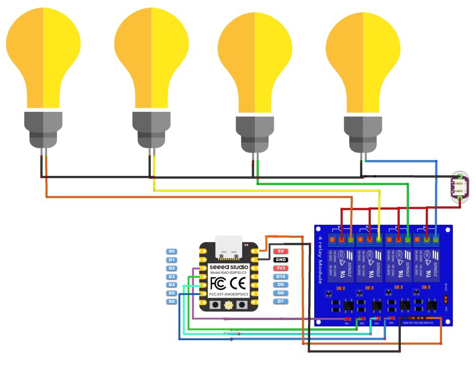
It’s just a basic circuit diagram. I am using digital pins 2, 3, 4, and 5 to control all the 4 relays.

I will be using my designed 4 channel relay module. If you want you can also use a 0ne-channel relay module. You can download the Gerber files from PCBWay. These are 12V relays, that’s why I will be using a separate 12V power supply. Anyway, I connected everything as per the circuit diagram, and now let’s take a look at the programming.
XIAO ESP32C3 Home Automation Code:
|
1 2 3 4 5 6 7 8 9 10 11 12 13 14 15 16 17 18 19 20 21 22 23 24 25 26 27 28 29 30 31 32 33 34 35 36 37 38 39 40 41 42 43 44 45 46 47 48 49 50 51 52 53 54 55 56 57 58 59 60 61 62 63 64 65 66 67 68 69 70 71 72 73 74 75 76 77 78 79 80 81 82 83 84 85 86 87 88 89 90 91 92 93 94 95 96 97 98 99 100 101 102 103 104 105 106 107 108 109 110 111 112 113 |
#include <ArduinoBLE.h> BLEService ledService("19B10000-E8F2-537E-4F6C-D104768A1214"); // Bluetooth® Low Energy LED Service // Bluetooth® Low Energy LED Switch Characteristic - custom 128-bit UUID, read and writable by central BLEByteCharacteristic switchCharacteristic("19B10001-E8F2-537E-4F6C-D104768A1214", BLERead | BLEWrite); const int Relay1 = D2; const int Relay2 = D3; const int Relay3 = D4; const int Relay4 = D5; int Rvalue; // received value from Bluetooth Application void setup() { Serial.begin(9600); //Baudrate // Set all the Relays as output pinMode(Relay1, OUTPUT); pinMode(Relay2, OUTPUT); pinMode(Relay3, OUTPUT); pinMode(Relay4, OUTPUT); // begin initialization if (!BLE.begin()) { Serial.println("starting Bluetooth® Low Energy module failed!"); while (1); } // set advertised local name and service UUID: BLE.setLocalName("HOME Automation"); // this will appear in the App search result. BLE.setAdvertisedService(ledService); // add the characteristic to the service ledService.addCharacteristic(switchCharacteristic); // add service BLE.addService(ledService); // set the initial value for the characeristic: switchCharacteristic.writeValue(0); // start advertising BLE.advertise(); Serial.println("BLE LED Peripheral"); } void loop() { // listen for Bluetooth® Low Energy peripherals to connect: BLEDevice central = BLE.central(); // if a central is connected to peripheral: if (central) { Serial.print("Connected to central: "); // print the central's MAC address: Serial.println(central.address()); while (central.connected()) { if (switchCharacteristic.written()) { Rvalue=switchCharacteristic.value(); // received value is stored in variable Rvalue. // we check the received commands and then accordingly control // all the relays. if (Rvalue==0) { Serial.println(switchCharacteristic.value() ); Serial.println("Relay1 OFF"); digitalWrite(Relay1, LOW); // changed from HIGH to LOW } else if(Rvalue==1){ Serial.println(F("Relay1 ON")); digitalWrite(Relay1, HIGH); // changed from LOW to HIGH } else if (Rvalue==2) { Serial.println(switchCharacteristic.value() ); Serial.println("Relay2 OFF"); digitalWrite(Relay2, LOW); // changed from HIGH to LOW } else if(Rvalue==3){ Serial.println(F("Relay2 ON")); digitalWrite(Relay2, HIGH); // changed from LOW to HIGH } else if (Rvalue==4) { Serial.println(switchCharacteristic.value() ); Serial.println("Relay3 OFF"); digitalWrite(Relay3, LOW); // changed from HIGH to LOW } else if(Rvalue==5){ Serial.println(F("Relay3 ON")); digitalWrite(Relay3, HIGH); // changed from LOW to HIGH } if (Rvalue==6) { Serial.println(switchCharacteristic.value() ); Serial.println("Relay4 OFF"); digitalWrite(Relay4, LOW); // changed from HIGH to LOW } else if(Rvalue==7){ Serial.println(F("Relay4 ON")); digitalWrite(Relay4, HIGH); // changed from LOW to HIGH } } } // when the central disconnects, print it out: Serial.print(F("Disconnected from central: ")); Serial.println(central.address()); } } |
Its just a simple code. I have already commented most of the instructions so you won’t have any problem in understanding the code. Anyway, You will need to add the ArduinoBLE library. You can see I have defined pins for all the 4 relays. I have also defined a variable Rvalue which I am going to use to store the commands from the Bluetooth application.
Inside the setup() function, you can see I have activated the Serial communication for debugging purposes. Once your code is ready, then you can deactivate this and you can remove all the serial.print() lines. Because, you won’t need to print anything on the Serial monitor.
I was talking about this name, this name will appear in the cell phone search results. So, if you want to use another name, just go ahead and change this.
Rest of the code is to receive the data from Bluetooth App and then to control the relays as per the commands. So, that’s all about the programming. Upload this code into the XIAO_ESP32C3, if you are not able to find the XIAO_ESP32C3 in the boards list, then you need to read my previous article on the XIAO ESP32C3 WiFi + Bluetooth Dev board.
Check the Seeed Studio Xiao ESP32C6.
Watch Video Tutorial

Discover more from Electronic Clinic
Subscribe to get the latest posts sent to your email.


