10.1” HMI intelligent TFT LCD UART Serial Communication
Last Updated on August 18, 2024 by Engr. Shahzada Fahad
Table of Contents
Description:
10.1” HMI intelligent TFT LCD UART Serial Communication- The 10.1” HMI Intelligent TFT LCD Module used in this video is sponsored by the Stone Technologies. Stone Technologies is a professional Manufacturer of HMI Intelligent TFT LCD modules. Depending on the application the Stone Technologies offers Industrial Type, Advanced type, and Civil Type Intelligent TFT LCD modules available in different sizes. The one I am using in this series of videos is the Civil Type 10.1 inch HMI display Module. For more information visit stoneitech.com.
In the previous tutorial, I explained how to design a graphical user interface using the images designed in Adobe Photoshop. How to use the button function, data variable function, Hardware parameter function and how to use the Drag adjustment, and Slider Scale function for controlling the screen brightness. So, I highly recommend first read the previous article and then you can resume from here.
In this article, I will be using the same GUI but with a little modification, this time I added the Sensors button

which will take me to the Sensors user interface.

We will serially print values in the Sensors boxes using the UART communication software. Control the user interface without pressing the on-screen buttons, this way you can jump to any image you want, control the screen brightness using commands sent serially. The main purpose of this tutorial is to help you understand how you can send commands and data serially to the HMI Intelligent TFT LCD Touchscreen Module. After, understanding the basic working principle, then I will write the Arduino Program. After reading this article, you will fully understand how to monitor and control this Intelligent TFT touchscreen module using the UART Serial communication.
Without any further delay let’s get started!!!
Note: For the step by step explanation, watch the TFT LCD UART communication video tutorial given at the end of this article.
Amazon Links:
Arduino Nano USB-C Type (Recommended)
*Disclosure: These are affiliate links. As an Amazon Associate I earn from qualifying purchases.
You can download the HMI Intelligent TFT LCD Touchscreen module User development Guide by clicking on the download link.
Download: User Development Guide of the tft lcd module by the stone technologies
In the User development Guide, you can find the addresses of all the registers.

As you can see in the datasheet, the address of the Brightness control register is 0x01, while the brightness value can be from 0x00 to 0x40 which equals 0 to 64 in decimal. You can read this register and also write into this register. The byte length is 1.
Section 2.2 in the User Development Guide, explains the Reading and Writing commands used to read data from a specific register or write data into a register.
The command 0x81 is used for reading while 0x80 is used for the writing. Let’s directly control the brightness using Serial communication. While the UART communication software is open, make sure the right communication port is selected. Write the following command
A5 5A 03 80 01 64
A5 and 5A are the serial port High and low bytes, which you can find on the Screen Parameter Configuration Window.
03 is the byte length,
80 is the command which is used to activate the writing operation
01 is the address of the LCD brightness control register.
64 is the value in hex, by changing this value the brightness can be controlled….
PIC_ID:
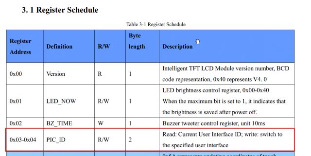
Now let’s do it for the PIC_ID. The register address for reading the current user interface or the image number is 0x04. And the register address to switch to the specified user interface or in simple words to switch to the specific image is 0x03. As you can see it is two bytes. Now let’s display the different images or user interfaces using serial communication…
Simply write this command.
A5 5A 04 80 03 00 01
A5 and 5A remain the same
04 is the total number of bytes
80 is the command to write into a register
03 is the register address which is used to switch to the specific image or user interface.
00 01 is the image number which is two bytes. By changing this number you can jump to any user interface or image.
So, this command displays the image number 1. It’s very simple, write the image number and that’s it.
Variable Memory read & writes commands:
Now for the Variable Memory, if you remember in the previous article, I used the data variable function for displaying the brightness value. This time we will do it using serial communication. The variable memory read and write commands are 0x82 and 0x83.
The command 0x82 is used for writing data into a variable memory, while the command 0x83 is used for reading the value stored in the variable memory.
As per the datasheet, the variable memory of the HMI Intelligent TFT LCD module is 128K byte which starts from 0x0000 to 0xFFFF.
Now let’s change this value using the serial communication. The command will be
A5 5A 05 82 6F 01 00 07
A5 and 5A are the serial port High and low bytes, which you can find on the Screen Parameter Configuration Window.
05 represents the byte length.
82 is the command which is used to activate the writing operation followed by the Variable memory which is 6F01, which is the same address I used in my previous tutorial.
00 07 is data in hex which I am going to store in the variable memory 6F01 which is two bytes.
Now let’s say if we want to read this data variable, for this we will write the command.
A5 5A 04 83 6F 01 01
A5 and 5A are the serial port High and low bytes.
04 is the total number of bytes.
6F01 is the variable memory.
01 This means how many bytes of data you want to read.
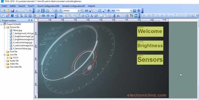
I modified the images and this time I added a button for the Sensors, when I press this button it jumps to the Sensors user interface.

The variable memory address of sensor number 1 is 0002 and the variable memory address of sensor number 2 is 0006. Let’s display 320 as the sensor1 value.
We can do this by simply writing this command.
A5 5A 05 82 00 02 01 40
A5 and 5A remain the same
05 is the total number of bytes,
82 is the command for writing
00 02 is the data variable address
01 40 is the hex value which is equal to 320 in decimal.
If we want to display 100 we simply write this command
A5 5A 05 82 00 02 00 64
Similarly changing the address we can display the same value in box2.
A5 5A 05 82 00 06 00 64
Now to read the data variable we write the following command.
A5 5A 04 83 00 06 01
So, that’s it for now. With this, my article on the TFT LCD UART Serial communication comes to an end. In the upcoming article, I will explain how to connect Arduino and display the sensor value on the screen.
If you have any questions, let me know in a comment. Don’t forget to Subscriber to my Website and YouTube channel “Electronic Clinic”.
TFT LCD UART communication Video Tutorial:
Discover more from Electronic Clinic
Subscribe to get the latest posts sent to your email.


I am trying to use the SSCom software. I reallize you cannot troubleshoot this for me., but can you advise if you used the converter card which should allow you to talk serially with the HMI from a PC. I have the civil STWCO43LT-01. The converter card was supplied by Stone with no documentation only a photo that shows it connected to a PC. On my PC the converter device will only allow me to connect at 9600 baud so I changed the data file in default directory on the HMI to this value but this did not work. WIth newer smart HMI the documentation seems to cover send commands with a format like ST<{\”cmd_code\”:\”sys_version\”,\”type\”:\”system\”}>ET rather than the previous hex commands, I tried the HEX commands and these do not work either.. Your informative video gave me hope that this might work but the Stone documentation lacks simple progressive steps to get the HMI to work.They do provide alot of project examples but I think they need to give simpler examples to get you started.The software for comms seemed to have changed significantly since your video.
I still have this hmi screen. I will use it again. And then i will let you know.