775 Motor Drivers or Speed Controllers, Different ways to control 775 Motor
Last Updated on August 17, 2024 by Engr. Shahzada Fahad
Table of Contents
775 Motor Drivers, Description:
775 Motor Drivers, Different ways to control 775 Motor- Recently I got myself these 775 DC motors which you might have seen in different projects. With these 775 DC motors you can make drill machines, you can make an Electric bike, you can make a grinder, an RC toy Car, RC boat, a solar fan, a water pump, a powerful table saw, and so on. In most applications you will need a speed controller in order to control the speed of 775 Motor.
Altium Designer:

Altium Designer is the world’s most trusted PCB design system. Altium Designer enables engineers to effortlessly connect with every facet of the electronics design process. Over 35 years of innovation and development focused on a truly unified design environment makes it the most widely used PCB design solution. With Altium Designer you can create PCB designs with an intuitive and powerful interface that connects you to every aspect of the electronics design process. Route it your way through any angle, tune for delay, Push, Slide, and Walkaround faster than ever. Interact and collaborate with mechanical designers like never before in a photo-realistic, 3D design environment. If you want to get started with the Altium designer, you can click on the get started.

So, in this tutorial, we are going to be looking at different ways to control the 775 motor. I have these 4 different types of Motor Drivers each one has different voltage and current ratings. We will take a closer look at the technical specifications, Pinout, connections, and practical demonstration. Throughout this article I will use 3S 11.1 volts Lipo Battery but you can use any DC Power supply between 10 and 24 Volts. Without any further delay, let’s get started!!!
Amazon Links:
1203B 3A PWM DC Motor Speed Controller
10V-60V DC Motor Speed Controller
320A Brushed ESC DC Motor Speed Controller
*Disclosure: These are affiliate links. As an Amazon Associate I earn from qualifying purchases.
775 Motor:

These are the 775 DC Motors with a shaft diameter of approximately 5mm and have the rated voltage of 24 volts and the maximum voltage is 36 volts. The rated speed of the 775 Motor is from 3500 to 7000 RPM “Revolutions per Minute”. This RPM depends on the supplied voltage
At 12V DC, Current is 0.14A, and Speed is 3500 RPM
At 18V DC, Current is 0.15A, and Speed is 4500 RPM
At 24V DC, Current is 0.16A, and Speed is 7000 RPM
775 motor specs
- Shaft Diameter: Approx. 5 mm
- Shaft length: Approx. 17 mm
- Body length: Approx. 66.7 mm
- Front steps diameter: Approx. 17.4 mm
- Former high level: Approx. 4.7 mm
- Body diameter: Approx. 42 mm
- Motor Overall Length: Approx. 98 mm
- Diagonal installation pitch: Approx. 28.8 mm
- Mounting hole size: M4
- Mounting hole: 2
- Cooling fan: Yes
- Rated voltage: 24 V (Max. 36V)
- Current Rating: 0.16 A
Features:
- The front is ball bearing and the back-end is copper
- 5 groups winding
- At a voltage of 12V-24V, large torque, low noise
Unlike other DC motors, the 775 Motor has also two wires and when connected with the desired voltage the shaft starts spinning. The direction of rotation can be controlled by swapping the voltage wires. Now, things get a little complicated when it comes to controlling the speed of the 775 DC motor because in the market we have different types of low-cost and expensive motor drivers offering low and high current ratings.
I have got 4 different motor drivers and we will use each one with the 775 Motor. These are not the only Motor Drivers, there are so many other types, but the ones I am going to use today are the most commonly used Motor Drivers or Motor Speed Controllers.
1203B 3A PWM DC Motor Speed Controller Module:

This is a 3A PWM DC 6V to 28V 1203B DC Motor Speed Controller Module. This DC Motor Speed Controller allows controlling the speed of a DC motor using the pulse width modulated DC voltage with a duty cycle fully adjustable from 5% to 100%. This motor speed controller can easily provide a continuous current of 3A to your DC motor or other DC loads. The speed of the DC motor can be controlled using the onboard potentiometer. The Module is also provided with terminal blocks which are used to connect the Motor and power supply. On the bottom side the terminals are clearly labeled as Power-, Power+, Motor+, and Motor-. The input supply voltage of this Motor driver is from 6V to 28VDC and has maximum output power of 80W.

Connect the GND wire with the Power- contact and connect the positive voltage wire with the Power+ and connect the two wires of the 775 Motor with the Motor+ and Motor- contacts of the Motor Driver. Our connections are completed and now we can start controlling the 775 DC Motor using the Potentiometer.

The voltage applied to the motor will be supply voltage applied to the circuit. It is recommended to add an appropriately rated fuse inline with the positive supply in order to protect the circuit from any possible short circuits.
10V-60V DC Motor Speed Controller:

This motor driver is the modified version of the 1203B Motor Driver. This motor driver can handle current up to 20A and accepts a wide range of input voltage from 10 to 60VDC. This motor driver also has got the same Potentiometer and input and output contacts. On the bottom side the contacts are clearly labeled as Power+, Power-, Motor+, and Motor-.
Connect the positive voltage wire with the Power+ and connect the GND wire with the Power- and connect the two wires of the 775 Motor with the Motor+ and Motor- contacts of the Motor Driver. Our connections are completed and now we can start controlling the 775 DC Motor using the Potentiometer.

The voltage applied to the motor will be supply voltage applied to the circuit. It is recommended to add an appropriately rated fuse inline with the positive supply in order to protect the circuit from any possible short circuits.
320A Brushed ESC DC Motor Speed Controller:
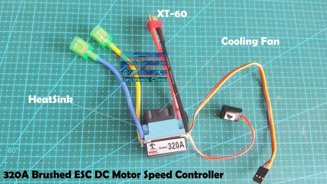
This is a 320A DC 7.2V to 16V Brushed ESC DC Motor Speed Controller designed for Ebikes, RC Cars, Trucks, and boats etc. We have two types of ESCs, these types of ESCs are used to control Brushless DC Motors while this one is used to control the speed and direction of Brushed DC motors. So, If you want to control your DC motor using a wireless transmitter and receiver then you need to purchase this High ampere Brushed ESC DC Motor Speed Controller.
This motor driver is also provided with a button, the wires were removed when I received this module, but anyways I short the two wires and now this module will remain ON until I remove the power supply.
On the top you can see this light blue color aluminum Heatsink and this small cooling fan. The Yellow and Blue Color wires are the Output wires and are connected with the DC Motor. These Red and Black wires with the XT-60 type connector are the input voltage wires, with the help of this it can be easily connected with the Lipo Batteries.
These three wires are connected with the controller board like Arduino or a wireless receiver. The yellow wire is the signal wire, with this wire we send the PWM signal from our controller board to control the speed and direction of the 775 DC motor, the Red wire is the 5V wire and it is used to power up the controller board or wireless receiver, and the brown wire is the ground wire.

On this side you can see we have these two switches on the top and bottom side. These switches are used to program the motor driver. The button on the top side is used to select the operation mode, it’s a three position switch and you can select any of these three modes F/B/R which is the Bidirectional mode, F/B which is the Unidirectional mode, and F/R which is the Climbing mode. The default value is Bidirectional.
The “two-way” mode, that is, the forward and reverse with brake mode, provides a reverse function, which is usually used for daily training. This mode uses a double
click reversing method, that is, when the throttle stick is pushed from the mid-point area to the reverse area for the first time, the motor just brakes and does not cause a reversing action; when the
throttle stick is quickly returned to the neutral point area and the second time When pushing to the reverse area (the so-called “double-click”), if the motor is stopped at this time, a reversing action will occur. If the motor is not stopped, it will not reverse, and it will still be braked. You need to return the throttle to the middle point and The
vehicle will only be reversed when pushed to the reverse zone . The purpose of this is to prevent the vehicle from accidentally reversing due to multiple brakes during driving.
“One-way” mode, that is, forward rotation with braking mode. The vehicle can only move forward and brake, but cannot reverse. This mode is usually used for racing.
“Climbing” mode, that is, direct forward and reverse mode, using one-click reversing mode, that is, when the throttle stick is pushed from the mid-point area to the reverse area, the
motor immediately generates a reversing action. This mode is generally used for special vehicles such as rock climbing vehicles .
2. Battery type: Lipo / NiMH. The default value is “Lithium”.
For this tutorial, I will continue with the default mode that is F/B/R.
I am going to use the Flysky Fs-i6 Receiver with the Motor Driver and then we will use the Flysky Transmitter to control the Forward and reverse movement of the 775 Motor.
Connect the two wires of the 775 DC motor with the two output wires of the 320A Brushed ESC DC Motor Speed Controller and the polarity doesn’t matter.
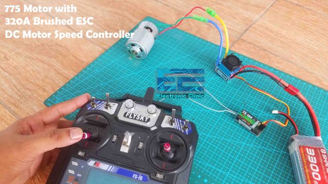
Now, connect the control signal wires with the receiver channel 3 which is the throttle channel. Make sure the signal wire, 5V wire, and GND wire connect with the exact pins on the receiver. So, that’s all about the connections, now we will connect the lipo battery, and then we are good to go.
First, we are going to control the 775 motors in the forward direction, to increase the speed simply move the throttle stick in the forward direction, and to slowly stop the motor move the stick in the downward direction. You can also apply the brake if you quickly move the throttle stick in the reverse direction. When the throttle stick is in the middle position, the motor simply stops, So you can use the upper part of the throttle stick for the forward movement and speed control, and the lower part of the throttle stick is used to apply the brake and control the speed of the DC motor in the reverse direction. You cannot quickly change the direction of rotation of the DC Motor, first you will have to stop the motor, and then you can slowly move the stick in the reverse direction this will change the direction of the DC motor. You can also try the other two modes the F/B and F/R. So, if you are planning to wirelessly control your RC Plane, Car, Boat, etc, using a 775 DC motor or any other DC motor then this is how you can do it. For the practical demonstration watch the video tutorial given at the end of this article.
775 Motor with L298N dc motor Driver:
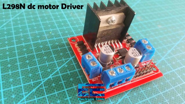
This is the L298N dual H-bridge motor driver. This motor driver can be used to control DC motors that have voltages between 5 and 35volts, with a peak current of up to 2amps. As this is a dual H-Bridge motor driver, it can be used to control the speed and direction of two DC motors at the same time. Now let’s take a closer look at the Pinout of the L298N Motor Driver.
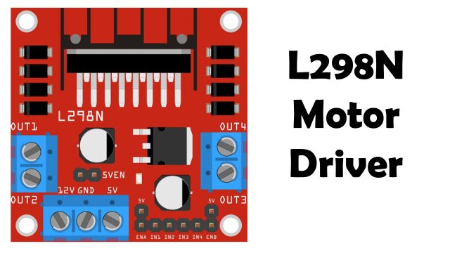
This module has three Blue color terminal blocks; this terminal block(on the Left side) will be used for motor A and is clearly labeled with out1 and out2, this is where we connect the two wires of the dc motor, this terminal block( on the Right side) will be used for motor B and is clearly labeled with out3 and out4, while this terminal block(on the bottom side) is labeled with 12v, ground, and +5v. The 12v terminal is used to supply the voltage to the dc motors, this voltage can be from 5 to 35volts, the ground terminal is connected with the ground of the external power supply and is also connected with the ground of the controller board, which in my case is the Arduino board which is based on the atmega328 microcontroller, while the +5v terminal will be connected with the Arduino’s 5v.
As you can see this motor driver also have some male headers and is clearly labeled as ENA, IN1, IN2, IN3, IN4, and ENB. The ENA and ENB are used to enable both motors. We can use jumper caps to enable both the motors and the motors will rotate at their maximum speeds or we can connect the ENA and ENB pins with the PWM pins of the Arduino and this way we can control the speed of DC motors.
The IN1 and IN2 pins are used for controlling the direction of motor A, while the IN3 and IN4 pins are used to control the direction of motor B. For demonstration purposes, I am going to control only one motor. Now, let’s take a look at the circuit diagram.
775 Motor with L298N Motor Driver, Circuit Diagram:

The two wires of the 775 Motor are connected with the OUT1 and OUT2. The positive and ground wires from the Lipo battery are connected with the 12v and GND contacts. 5V from the Arduino is connected with the 5V contact. Make sure the ground of the L298N Motor driver is also connected with the ground of the Arduino. The ENA, IN1, and IN2 pins are connected with the Arduino Pins 10, 9, and 8. The middle leg of the Potentiometer is connected with the Analog pin A1, while the other two legs of the Potentiometer are connected with the 5V and GND.

I connected everything as per the circuit diagram; my interfacing is completed and now let’s take a look at the programming.
775 Motor Arduino Code:
|
1 2 3 4 5 6 7 8 9 10 11 12 13 14 15 16 17 18 19 20 21 22 23 24 25 26 27 28 29 30 31 32 33 |
<span style="font-family: 'times new roman', times, serif; font-size: 14pt;">int ena = 10; int in1 = 9; int in2 = 8; int sc = A1; //speed controlling Potentiometer int mspeed = 0; // motor speed, the variable resistor value will be stored in this variable void setup() { // put your setup code here, to run once: Serial.begin(9600); pinMode(ena, OUTPUT); pinMode(in1, OUTPUT); pinMode(in2, OUTPUT); pinMode(sc, INPUT); analogWrite(ena, 0); } void loop() { mspeed = analogRead(sc); mspeed = map(mspeed, 0, 1023, 0 , 255); analogWrite(ena, mspeed); // forward digitalWrite(in1, HIGH); digitalWrite(in2, LOW); } </span> |
I started off by defining pins for the ENA, IN1, IN2, and Potentiometer. I set the ENA, IN1, and IN2 pins as the OUTPUT and Potentiometer as the INPUT.
Inside the loop() function, we are simply reading the potentiometer, then we map the value, and then use the mapped value to control the speed of the 775 Motor. IN1 and IN2 as you know are used to control the direction, this HIGH and LOW combination runs the 775 motor in forward direction and if you change HIGH into LOW and LOW into HIGH then the 775 motor will run in the reverse direction. So, that’s all about the programming.

Watch Video Tutorial:
Discover more from Electronic Clinic
Subscribe to get the latest posts sent to your email.


Excellent information
Thanks
very helpful indeed, i understood that a controller of 10A is sufficient for a 12v 775 motor . is it right or i am still wrong ? please reply
thank you