AC Alternating Current Generation, Alternating current in RC, RL, and RLC circuits
Last Updated on September 22, 2020 by Engr. Shahzada Fahad
Table of Contents
Alternating Current:
AC Alternating Current Generation, Alternating current in RC, RL, and RLC circuits–
A current of constant amplitude and which continuously varies in magnitude with time and changes its direction periodically is called Alternating current. In the given figure the upper portion of the alternating current represent positive current and the lower portion of the alternating current represent negative current.
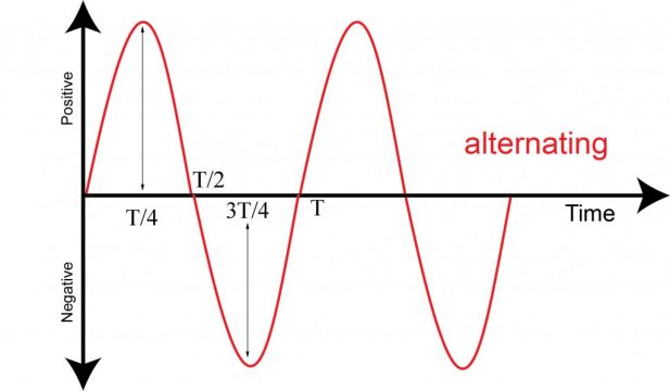
In the above graph we can see that at the start the current is zero but it increases with time and at t/4 it has maximum current which is known as the peak value of the current. From t/4 to t/2 it starts decreasing on t//2 its value will be zero. On t/2 it will changes its direction and the current will become negative from t/2 to 3t/4 interval its value will be negatively increases and at 3t/4 it has maximum negative value. From 3t/4 it will start decreasing and at T it will be zero. The upper portion of the wave is positive and the lower portion of the wave is negative. This wave form is known as sinusoidal wave. When the wave will complete its time period will be “T”. The wave will perform simple harmonic motion means it will repeat itself with the regular interval of time.
Alternating current can be produced in variety of waveforms square wave, triangular waves, rectangular waves but the engineers still choose to adopt sine wave form. It has following advantages:
The sine waveform produces the least disturbance in the electrical circuit and is the smoothest and efficient waveform. For example when current in a capacitor in a inductor or in a transform is sinusoidal, the voltage across the element is also sinusoidal. This is not true of any other waveform.
The mathematical computations connected with alternating current work are much simpler in the waveform.
Production of AC current:
The electrical machine by which the alternating current is produced is known as the alternating current generator or dynamo. There are two essential components of the generator or dynamo which are field magnet and armature. The armature is made on soft iron core and makes large number of turns of insulated copper wire. Then this armature is placed in a uniform magnetic field and rotate it with uniform angular velocity. The flux of the coil will change and induce emf will be produced it the coil is closed then induce emf will also be produce which is known as alternating current. AC generator is based on the electromagnetic induction.

A loop AB carried by a spindle DD rotated at a constant speed in anticlockwise direction in a uniform magnetic field due to poles NS. The ends of the loops are brought out to two slip rings C1 and C2, attached to an insulated from DD. Bearing on these rings are carbon brushes E1 and E2, which are connected to an external resistor R.
When the plane of the loop is horizontal the two sides A and B are moving parallel to the direction of the magnetic flux; it follows that no flux is being cut and no emf is being generated in the loop. The coil sides are cutting the flux and therefore an emf is induced in the coil sides. Since the coil sides are moving inn opposite direction, the emf act in opposite directions. However they do act in the same direction around the coil so that the emf which appears at the brushes is twice that which is induced in a coil side. Once the coil reaches the perpendicular peak position the rate of cutting reaches a maximum. Therefore the emf falls to zero by the time the coil has rotated parallel to the magnetic field.

The induced emf in the position shown in Fig (e ) of particular interest. At first sight it appears that the diagram is same as that of Fig (b) but in fact it is side A which bears the cross while side B has the dot. This means that the emf is of the same magnitude but of the opposite polarity. The observation also applies to Fig(f). it follows that the variation of induced emf during the second half of the cycle of rotation is the sane as during the first half but the polarity of the emf has reversed.
We can now analyse the general case shown in fig(b) in which coil AB is shown after it has rotated through an angle Φ from the horizontal position namely the position of zero emf. Suppose the peripheral velocity of each side of the loop to be u meters per second then at the instant shown in figure. This peripheral velocity can be represented by the length of a line AL drawn at right angles to the plane of the loop. We can resolve AL into two components, AM and AN, perpendicular and parallel respectively to the direction of the magnetic flux as figure.
AC terminologies:
Alternating current changes continuously in magnitude and alternates in direction at regular intervals of time. It rises from zero to maximum positive value, falls to zero again. The important AC terminology is defined below:
Instantaneous value:
The magnitude of a waveform at any instant in time is the instantaneous value. The instantaneous values of alternating current are represented by I. As an example the instantaneous values of current at 0, 90 and 270 are 0, +VM and –VM respectively.
Cycle:
One complete set of positive and negative values or each repetition of a variable quantity recurring at regular interval of an alternating quantity is known as a cycle. A cycle can also be defined in terms of angular measure. One cycle corresponds to 360 or 2π radians.
Time period:
The time taken in seconds to complete one cycle or the duration of one cycle of an alternating quantity is called its time period. It is generally represented by T.
Peak value:
The maximum instantaneous value or the maximum value reached by an AC waveform from its zero value is known as its peak value.
Peak to peak value:
The maximum variation between the maximum positive instantaneous value and the maximum negative instantaneous value or the difference between negative peak and positive peak is the peak to peak value. For a sinusoidal waveform this is twice the peak value. The peak to peak value is represented by IPP .
Peak amplitude:
The maximum instantaneous value measured from the mean value of a waveform is the peak amplitude. Later we will find how to determine the mean value but for the most sinusoidal alternating voltages and current the mean value is zero. The peak amplitude is Ip The peak amplitude is generally described as the maximum value.
Frequency:
The number of cycle that occur in one second is termed the frequency of Heinrich Rudolf Hertz, who is in 1888, was the first to demonstrate experimentally the existence and properties of electromagnetic radiation predicted by Maxwell in 1865. It follows that frequency f is related to the period T by the relation.
Where T is the time period in seconds and f is the frequency of the wave form in hertz and. Assuming each graph to be drawn to the same scale of time, the effect of increasing the frequency as shown. The diagrams assume frequencies of 1000Hz (1KHz), 2KHz and 2.5KHz.
Example:
A coil of 100 turns is rotated at 1500 r/min in a magnetic field having a uniform density of 0.05T, the axis of rotation being at right angles to the direction of the flux. The mean area per turn is 40 . Calculate
- The frequency
- The period
- The maximum value of the generated emf
- The of the generated emf when the coil has rotated through 30 from the position of zero emf
Solution:
- Since the emf generated in the coil undergoes one cycle of variation when the coil rotates through one revolution,
Frequency= no of cycles per second
= no of revolutions per second
=1500/60 = 25Hz
- Period = time of cycle
= 1/25=0.04s
- EMF
Em=2π×0.05×0.004×100×25
= 3.14 V
For ɵ=30, sin30=0.5
e= 3.14×0.5=1.57V
Average and rms values of an alternating current:
Must electrical energy is provided by rotating a.c generators operating on the principles. The emf and the resulting currents are for the most part sinusoidal which is the waveform on which we have concentrated. However the use of electronic switching has resulted in many circuits operating with waveforms which are anything but sinusoidal, square waveforms are especially common in communication circuits.
Let us first consider the general case of a current the waveform of which cannot be represented by a simple mathematical expression. For instance, on no load. If n equidistant mid-ordinates I1, I2 etc. are taken over either the positive or the negative half cycle, then average value of current over half a cycle is
Iavg = i1+i2+i3……in/n
Or, alternatively, average value of current is
Area enclosed over half – cycle / length of base over half – cycle
The method of expressing the average value is the more convenient when we come to deal with sinusoidal waves.
This is due the fact that it is the power produced by the electric current that usually matters. Thus if the current passed through resistor having resistance R ohms, the heating of i1 is the i12 the R of i2 is i22R etc. The variation of the heating effect during the second half-cycle is exactly the same as that during the first half-cycle.
Average heating effect = i12R+i22R+i32R+……in2R / n
I=√((i12+i22+i32+⋯in2 )/n)
= square root of the mean of the squares of current
= root-mean-square value of the current
The quantity us also termed the effective value of the current. It will be seen that the rms or effective value of an alternating current is measured in term of the direct current that produce the same heating effect in the same resistance. Alternatively the average heating effect caused by the alternating current can be expressed as follows:
Average heating effect over half-cyle = area enclosed by i12R curve ober half cycle / length of the base
This is more convenient expression to use when deriving the rms value of a sinusoidal current.
Alternating current in resistive circuit:
Consider a circuit having a resistance R ohms connected across the terminals of an a.c generator and suppose the alternating voltage to be represented by the sine wave. If the value of the voltage at any instant B is v volts, the value of the current at that instant is given by:
i= v/R
When the voltage is zero, the current is also zero; and since the current is proportional to voltage, the waveform of the current is exactly the same as that of the voltage. Also the two quantities are in phase with each other; that is they pass through their zero values at the same instant and attain their maximum values in a given direction at the same instant.

If V_m and I_m are the maximum values of the voltage and current respectively, it follows that
Im=Vm/R
But the rms value of a sine wave can be calculated we know that 0.707 times the maximum value can gives us the rms value.
r.m.s value of Voltage = V = 0.707 Vm
r.m.s value of Current = I = 0.707 Im
Substituting for Im and Vm we have
I/0.707=V/0.707R
I=V/R
Hence Ohm’s law can be applied without any modification to an ac circuit possessing resistance only.
If the instantaneous value of the applied voltage is represented by
v=V_m sinωt
Then instantaneous value of current in a resistive circuit is
i= (Vm sinωt)/R
The phase representing the voltage and current in a resistive circuit. the two phasors are coincident but are drawn slightly apart so that the identity of each may be clearly recognized. It is usual to draw the phasors in the position corresponding to ωt=0. Hence the phasors representing the voltage and current.
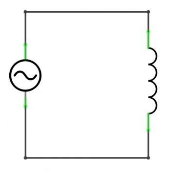
Alternating current in inductive circuit:
Let us consider the effect of a sinusoidal current flowing through a coil having an inductance of L henrys and a negligible resistance. The quarter cycle has been divided into three equal intervals, OA, AC and CF seconds. During interval OA, the current increases from zero to AB; hence the average rate of change of current is AB/OA amperes per second, and is represented by ordinate JK drawn midway between O and A.

When the current passes through an inductor which is a two terminal electrical component it will resists changes in electric current. The inductor is in coil shape. Consider an alternating voltage applied to a pure inductance of L. when a sinusoidal current I flow in time t then:
back emf=L ∆I/∆t
Is induced due to the inductance of the coil. This back emf at every instant opposes the change in current through the coil. As there is no drop in potential so the applied voltage has to overcome the back emf.
Applied alternating voltage = back emf
So the energy which is required in building up current in inductance L, is returned back during the decay of the current.
Let the equation for the alternating current is
I=Imsinωt
This changing current sets up a back emf in the coil. The magnitude of back emf is:
back emf=L ∆I/∆t
To maintain a constant current the applied emf must be constantly applied. The magnitude of applied voltage is:
V=L ∆I/∆t
V=L (∆Imsinωt)/∆t
V=LIm∆sinωt/∆t
Using the result of simple calculus
∆sinωt/∆t= ωcosωt
Putting the values we get:
V=ωLIm cosωt
ωLI_m=Vm
V=Vm cosωt
V=Vmsinωt+π/2)
From the above equations it is clear that current lags behind the voltage by π/2 radians or 90 degrees. It also shows that current lags the voltage in an inductive coil. Inductance opposes the change in current and serves to delay the increase or decrease of current in the circuit. This cause the current to lag behind the applied voltage which is indicated by the phasor diagram. Inductance opposes the flow of current in the circuit. So the opposition offered by an inductor to the flow of A.C is called inductive reactive reactance X_L.
Therefore in analogy to ohm law we can write:
Vm=Im XL
Since the inductive reactance is ratio of voltage to current. So
V_m/Im =XL
Where ωLIm=Vm
(ωLI_m)/Im =XL
XL=ωL
XL= 2πfL
The reactance of coil depends upon frequency of A.C. in case of D.C inductive reactance XL= 0.
Example 1:
A pure inductive coil allows an alternating current of 20A to flow from 220V, 50HZ supply. Find
Inductive reactance
Inductance of a coil
Power absorbed
Equation for voltage and current
Solution :
Inductive reactance
XL=V/I
XL=220/20
XL=11Ω
Inductance of a coil
XL= 2πfL
L=XL/2πf
L=11/(2π×50)
L=0.035H
Power absorbed
The power absorbed will be zero
Equation for voltage and current
Vm=220×√2=311.1 V
Im=20×√2=28.28 A
ω=2πf
ω=2π×50
ω=314 rad s^(-1)
Since in pure inductive circuit current lags behind the voltage by π/2. The equations are:
V=Vmsinωt)
V=311.1sin314t) V
I=Imsinωt-π/2)
I=28.28sin314t-π/2)
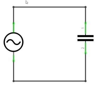
Alternating current in capacitive circuit:
Consider an alternating voltage is applied to a capacitor of capacitance C. when an alternating voltage is applied across the plates of a capacitor, the capacitor is charged in one direction and then in the other as the voltage reverses. The result is that electron move to and fro around the circuit, connecting the plates, thus constituting alternating current.
The basic relation between the charge q on the capacitor and voltage V across its plates is i.e q=CV holds at every instant. Let the applied alternating voltage is:
V=Vmsinωt)
Then at any instant I be the current and q be the charge on the plates.
Charge on a capacitor
q=CV=CVmsinωt
I=∆q/∆t
I=(∆(CVmsinωt)))/∆t
By using the formula
∆sinωt/∆t= ω cosωt
I=CVm ω cosωt
I=CVm ωsinωt+π/2)
Im=CVm ω
I=Im sinωt+π/2)
The current leads the voltage by π/2 radians. Hence in a pure capacitance, current leads the voltage by 90 degrees. Capacitance opposes the change in voltage and serves to delay the increase or decrease of voltage across the capacitor.
This cause the voltage to lag behind the current. This is also illustrated in the phasor diagram. Like inductance which opposes the flow of A.C., capacitance also opposes the flow of Alternating current in the circuit. From the above:
Im=CVm ω
Vm/Im =1/Cω
Just like ohm law the ratio of V/I is the measure of opposition offered by a resistor to the flow of current. In case of capacitor this opposition is capacitive reactance which opposes the flow of current.
Vm/Im =Vc/I=1/Cω
Clearly the opposition offered by capacitance to current flow is 1/Cω. This quantity 1/Cω us called capacitive reactance Xc of the capacitor. It has the same dimensions as resistance and is, therefore measured in Ω.
I=Vc/Xc
Where the capacitive reactance is:
Xc= 1/ωC=1/2πfC
The capacitive reactance depends upon frequency of A.C. In case of D.C Xc has infinite value.
R.L series AC circuit:
In an AC circuit that contains the inductance, L and resistance, R the voltage, V will be the phasor sum of two component voltages, VR and VL. This means that the current flowing through the coil will still lag the voltage, but by an amount less than 90 degrees depending upon the values of VR and VL. The new phase angle between the voltage and current is known as the phase angle Φ of the circuit. V is the rms value of the applied voltage, I is the rms value of current and VL=IXL.
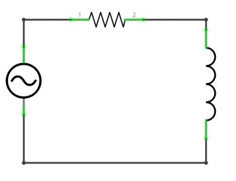
The voltage drop VR=IR is in the phase with current and is represented in magnitude and direction by the phasor. The voltage drop VL=IXL leads the current by 90 degrees and is represented in magnitude and direction by the phasor. The applied voltage V is the phasor sum of these two drops.
V2=VR2+VL2
V=√(VR2+VL2 )
V=√(IR2+IXL2 )
V=I√(R2+XL2 )
I=V/√(R2+XL2)
The quantity √(R2+XL2 ) is the opposition offered to current flow and is called impedance of the circuit. It is represented by Z and is measure in ohms.
The phasor diagram show that circuit current I lags behind the applied voltage V by Φ. The fact also illustrated in the wave diagram. The value of phase angle Φ can be determined from the phasor diagram.
tanΦ=XL/R
since XL and R are known, Φ can be calculated if the applied voltage is
V=Vmsinωt)
then the equation for the circuit current will be:
I=Imsinωt-Φ)
Inductive circuit current lags behind the applied voltage. The angle Φ of lagging is greater than 0 degree but less than 90 degree. It is determined by the ration of inductive reactance to resistance in the circuit. The greater the value of this ratio the greater will be the phase angle Φ.
R.C series A.C circuit :
Consider AC circuit that contains both capacitor, C and resistance R which are connected in series with each other. The voltage, V across the combination is equal to the phasor sum of two component voltages VR and V_C where VR=IR and 〖 V〗_C=IX_C. In order to draw a vector diagram for a capacitance a refrence must be found. In a series AC circuit the current is common and can therefore be used as the reference source because the same current flows through the resistance and capacitance. The individual vector diagrams for a pure resistance and pure capacitance.
The voltage drop is in phase with the current and is represented by the phasor OA. The voltage drop V_C=IX_C lags behind the current by 90 degrees and represented in magnitude and direction by the phasor AB. The applied voltage V is the phasor sum of these two drops.
V^2=VR2+VC2
V=√(VR2+VC2 )
V=√((IR)2+(IXC)2 )
V=I√(R2+XC2 )
I=V/√(R2+XC2 )
The quantity √(R2+XC2 ) offer opposition to current flow and is called impedance of the circuit.
I=V/Z
Where Z=√(R2+XC2 )
The phasor diagram shows that circuit current I leads the applied voltage V by Φ. This fact is also illustrated in the wave diagram and impedance triangle of the circuit.
The value of the phase can be determined as under:
tanΦ=-XC/R
RLC series AC circuit:
Many ac circuits are very useful for us which includes resistance, inductive reactance and capacitive reactance. In this section we will look at some implications if connecting resistor (R ), an inductor (L) and a capacitor (C) together which is called series RLC circuit. The simplest and most important ac circuit we can analyse is the series RLC circuit.
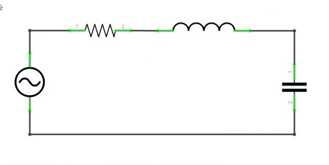
The analysis of this circuit is quite easy since all the circuit element shares the same current. We can draw a phasor diagram for the current and voltages across the inductor, capacitor and resistor. The P.D across the R is V_R=IR in this case V_R is in the phase with I. The P.D across L, is VL=IXL in this case V_Lleads I by 90 degree. The P.D across C, is VC=IXC in this case where VC lags I by 90 degree V_Land VC are thus 180 degree out of phase. In phasor diagram AB represents V_R, BE represents VL and BD represents VC.
It follows the circuit can either be effectively inductive or capacitive depending upon which voltage drop V_Lor V_C is predominant. If VL> V_C then the net voltage drop across L-C combination is VL– VC and their resultant is in the direction VL represented by BC. Therefore, the applied voltage V is the phasor sum of V_R and VL– V_C and represented by AC.
V^2=VR2+(VL– VC)2
V=√(VR2+(VL– VC)2)
V=√((IR)2+(IXL-IXC)2)
V=I√(R2+(XL-XC)2)
V= IZ
Z=√(R2+(XL-XC)2 )
The quantity XL-X_C is called the reactance of the circuit, denoted by X.
X^2 =(XL-XC)2
Finally we can write
Z=√(R2+(XL-XC)2 )
Z=√(R2+X2 )
It is the opposition offered to current flow and is called impedance of the circuit.
Circuit power factor cosΦ=R/Z
cosΦ=R/√(R2+(XL-XC)2)
Since XL,XC and R are known, phase angle Φ of the circuit can be determined.
tanΦ= (VL-VC)/V_R
tanΦ=(XL-XC)/R
tanΦ= X/R
So if the current is represented by a cosine function
I=Im cos(ωt)
The source voltage leads the current by an angle and its equation is
I=Imcos(ωt+Φ)
When XL-XC is positive (i.e XL>XC), phase angle Φ is positive and the current will be inductive. In other words in such a case the circuit current I lags will lag behind the applied voltage V by Φ.
When XL-XC is negative (i.e X_C>XL), phase angle Φ is negative and the current will be capacitive. In other words in such a case the circuit current I leads the applied voltage V by Φ.
When XL-XC=0 (i.e XC=XL), the circuit is purely resistive. In other words circuit current I and applied voltage V will be in phase i.e Φ=0 the circuit will then have unity power factor.
Discover more from Electronic Clinic
Subscribe to get the latest posts sent to your email.