Arduino esp8266 wifi Home/Office Automation System
Last Updated on February 25, 2024 by Engr. Shahzada Fahad
Table of Contents
Description:
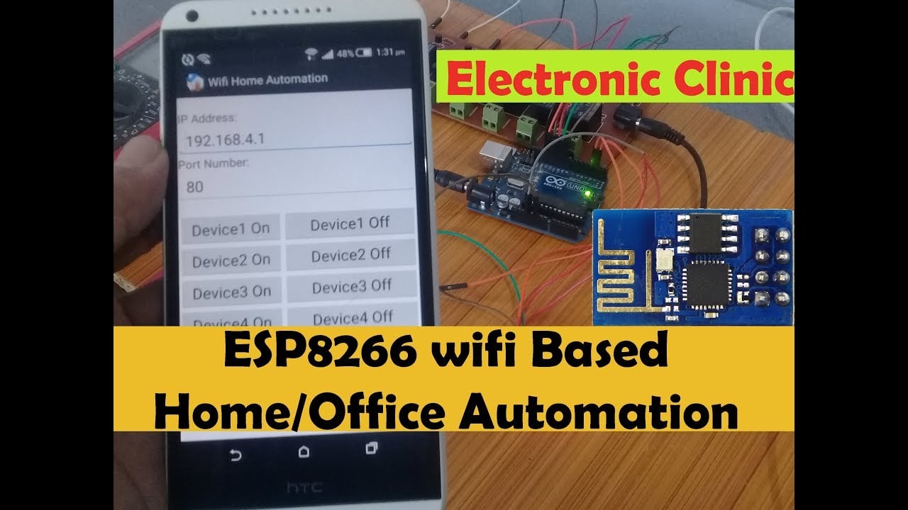
ESP8266 Arduino- In this tutorial, you will learn how to make your own ESP8266 wifi module based Home/ Office automation Project along with a feedback system using an application on your android cell phone. This project is based on the famous ESP8266 wifi module. With the help of this project the electrical loads AC/Dc can be controlled using your android cell phone. All the commands are processed by the Arduino Uno.
As you know any program which is written for the Arduino Uno can also Run on the Mega. So the program written for this project will also work on the Arduino Mega. To use this project you will need to connect your ESP8266 Wifi module and cell phone with the same WIFI network. This is actually an offline automation system. This project can be used at homes, offices, colleges, universities, and so on.
For the Worldwide control system, I recommend you should use the Nodemcu ESP8266 Wifi Module because the use of the Nodemcu ESP8266 Module is very simple, you don’t have to update the firmware, the coding is very simple.
Nodemcu ESP8266 based Home/Office Automation System.
You can also use the ESP32 Module, its use is just like the Nodemcu ESP8266 Wifi Module. You can add multiple analog sensors and you can also add digital sensors. I have also developed the home automation system using the ESP32 Module, i recommend you should read this article “ESP32 Home Automation Project, ESPRESSIF Home Automation”
This Tutorial covers.
esp8266 wifi module software/firmware update
use of at commands
complete project circuit diagram
interfacing ESP8266 with Arduino
Arduino ESP8266 programming and finally
Testing the Home/Office Automation project.
For the firmware update, you can watch a video given at the end of this Article.
Without any further delay, let’s get started!!!
Amazon Links:
Other Tools and Components:
Super Starter kit for Beginners
PCB small portable drill machines
*Please Note: These are affiliate links. I may make a commission if you buy the components through these links. I would appreciate your support in this way!
ESP8266 with Arduino Circuit Diagram:
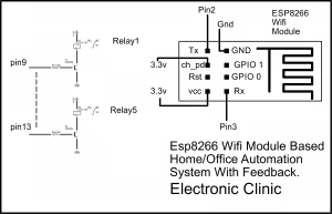
The ESP8266 WIFI module Tx pin is connected with the Arduino’s pin number 2. The ch_pd pin of the ESP8266 WIFI module is connected with the Arduino’s pin number 3.3 volt. The RST pin of the wifi module is left unconnected. The VCC pin of the ESP8266 WIFI module is connected with the 3.3-volt pin of the Arduino Uno. The Ground pin of the ESP8266 WIFI module is connected with the Arduino’s Ground. The Rx pin of the wifi module is connected with pin number 3 of the Arduino Uno, while the GPIO 1 and GPIO 0 are not connected.
4 relays are connected with the Arduino pins 9 to 13. If you want you can increase or decrease the number of relays. The relays used in this project are of the type SPDT “ these are 12V and 10A relays. As you can see in the circuit diagram a 10k resistor and 2n2222 NPN transistor is connected with each relay. The 10k resistor and 2n2222 makes the driver and is used to operate this relay. Due to the voltage difference, a 12v relay cannot be directly operated by the controller so that’s why we need a driver circuit to control a relay. The Selection of the Transistor entirely depends on the relay coil resistance.
To find the relay coil resistance you will need a multimeter. Set the multimeter on the resistance and connect both the test leads of the digital multimeter with the two legs of the relay which has the coil. After you find the Coil resistance, then the next step is to use ohm’s law
V = I R
Now after putting values in this formula, you can find the Current. now depending on the value of the current calculated, we select a transistor whose collector current is greater than the relay coil current. this is the current needed to energize the relay coil. Select a transistor whose collector is approximately 3 times greater than the calculated value. This way the transistor will never heat up.
I selected 2n2222 NPN transistor and if you check the datasheet of this transistor you will find that its collector current is much greater than the relay coil current, which is best. Moreover the 2n2222 transistors are really cheap and are easily available in every electronics shop.
If you want to control your home or office appliances from remote locations, then I highly recommend you should use Nodemcu ESP8266 wifi module and Blynk Application. I have so many tutorials on Blynk Application and Nodemcu esp8266 wifi module. The use of Nodemcu esp8266 wifi module is really easy as compared to the ESP8266 wifi module.
If you have any questions regarding this project, you can let me know in a comment.
Download:
Cell phone application apk file: Wifi
ESP8266 Arduino Programming:
|
1 2 3 4 5 6 7 8 9 10 11 12 13 14 15 16 17 18 19 20 21 22 23 24 25 26 27 28 29 30 31 32 33 34 35 36 37 38 39 40 41 42 43 44 45 46 47 48 49 50 51 52 53 54 55 56 57 58 59 60 61 62 63 64 65 66 67 68 69 70 71 72 73 74 75 76 77 78 79 80 81 82 83 84 85 86 87 88 89 90 91 92 93 94 95 96 97 98 99 100 101 102 103 104 105 106 107 108 109 110 111 112 113 114 115 116 117 118 119 120 121 122 123 124 125 126 127 128 129 130 131 132 133 134 135 136 137 138 139 140 141 142 143 144 145 146 147 148 149 150 151 152 153 154 155 156 157 158 159 160 161 162 163 164 165 166 167 168 169 170 171 172 173 174 175 176 177 178 179 180 181 182 183 184 185 186 187 188 189 190 191 192 193 194 195 196 197 198 199 200 201 202 203 204 205 206 207 208 209 210 211 212 213 214 215 216 217 218 219 220 221 222 223 224 225 226 227 228 229 230 231 232 233 234 235 236 237 238 239 240 241 242 243 244 245 246 247 248 249 250 251 252 253 254 255 256 257 258 259 260 261 262 263 264 265 266 267 268 269 270 271 272 273 274 275 276 277 278 279 280 281 282 283 284 285 286 287 288 289 290 291 292 293 294 295 296 297 298 299 300 301 302 303 304 305 |
#include <SoftwareSerial.h> #define DEBUG true SoftwareSerial esp8266(2,3); // rx, tx // This means that you need to connect the TX pin of the esp to the Arduino's pin 2 // and the RX pin of the esp to the Arduino's pin 3 int relay1 = 9; int relay2 = 10; int relay3 = 11; int relay4 = 12; int relay5 = 13; int flag1 = 0; int flag2 = 0; int flag3 = 0; int flag4 = 0; int flag5 = 0; void setup() { Serial.begin(115200); esp8266.begin(115200); // your esp's baud rate might be different pinMode(relay1,OUTPUT); pinMode(relay2,OUTPUT); pinMode(relay3,OUTPUT); pinMode(relay4,OUTPUT); pinMode(relay5,OUTPUT); digitalWrite(relay1, LOW); digitalWrite(relay2, LOW); digitalWrite(relay3, LOW); digitalWrite(relay4, LOW); digitalWrite(relay5, LOW); sendCommand("AT+RST\r\n",2000,DEBUG); // reset module sendCommand("AT+CWMODE=2\r\n",1000,DEBUG); // configure as access point //sendCommand("AT+CWJAP=\"mySSID\",\"myPassword\"\r\n",3000,DEBUG); //delay(10000); sendCommand("AT+CIFSR\r\n",1000,DEBUG); // get ip address sendCommand("AT+CIPMUX=1\r\n",1000,DEBUG); // configure for multiple connections sendCommand("AT+CIPSERVER=1,80\r\n",1000,DEBUG); // turn on server on port 80 Serial.println("Server Ready"); } void loop() { char pinNumber = '0'; char secondNumber = '0'; if(esp8266.available()) // check if the esp is sending a message { //delay(1000); // wait for the serial buffer to fill up (read all the serial data) // get the connection id so that we can then disconnect char connectionId = '0'; //esp8266.read(); // subtract 48 because the read() function returns // the ASCII decimal value and 0 (the first decimal number) starts at 48 esp8266.find("pin="); // advance cursor to "pin=" char pinNumber = (esp8266.read()); // get first number i.e. if the pin 13 then the 1st number is 1 Serial.println("pin number:"); Serial.print(pinNumber); char secondNumber = (esp8266.read()); Serial.println("second number:"); Serial.println(secondNumber); String content ="" ; // relay1 if((pinNumber == '1')&&(secondNumber == '1') && ( flag1 == 0)) { digitalWrite(relay1, HIGH); content = "relay1 is ON "; flag1 = 1; } if((pinNumber == '1')&&(secondNumber == '8') && (flag1 == 1) ) { digitalWrite(relay1, LOW); content = "Relay1 is OFF "; flag1 = 0; } // relay2 if((pinNumber == '2')&&(secondNumber == '3') && ( flag2 == 0)) { digitalWrite(relay2, HIGH); content = "relay2 is ON "; flag2 = 1; } if((pinNumber == '6')&&(secondNumber == '6') && (flag2 == 1) ) { digitalWrite(relay2, LOW); content = "Relay2 is OFF "; flag2 = 0; } // relay3 if((pinNumber == '4')&&(secondNumber == '4') && ( flag3 == 0)) { digitalWrite(relay3, HIGH); content = "relay3 is ON "; flag3 = 1; } if((pinNumber == '7')&&(secondNumber == '7') && (flag3 == 1) ) { digitalWrite(relay3, LOW); content = "Relay3 is OFF "; flag3 = 0; } // relay4 if((pinNumber == '9')&&(secondNumber == '9') && ( flag4 == 0)) { digitalWrite(relay4, HIGH); content = "relay4 is ON "; flag4 = 1; } if((pinNumber == '6')&&(secondNumber == '4') && (flag4 == 1) ) { digitalWrite(relay4, LOW); content = "Relay4 is OFF "; flag4 = 0; } // relay5 if((pinNumber == '3')&&(secondNumber == '3') && ( flag5 == 0)) { digitalWrite(relay5, HIGH); content = "relay5 is ON "; flag5 = 1; } if((pinNumber == '9')&&(secondNumber == '5') && (flag5 == 1) ) { digitalWrite(relay5, LOW); content = "Relay5 is OFF "; flag5 = 0; } // feedback if((pinNumber == '5')&&(secondNumber == '5') ) { if (digitalRead(relay1) ) content += "Relay1 = ON"; else content += "Relay1 = OFF"; if (digitalRead(relay2) ) content += " Relay2 = ON"; else content += " Relay2 = OFF"; if (digitalRead(relay3) ) content += " Relay3 = ON"; else content += " Relay3 = OFF"; if (digitalRead(relay4) ) content += " Relay4 = ON"; else content += " Relay4 = OFF"; if (digitalRead(relay5) ) content += " Relay5 = ON"; else content += " Relay5 = OFF"; } //****************************************** sendHTTPResponse(connectionId,content); // make close command String closeCommand = "AT+CIPCLOSE="; closeCommand+=connectionId; // append connection id closeCommand+="\r\n"; sendCommand(closeCommand,1000,DEBUG); // close connection } } /* * Name: sendData * Description: Function used to send data to ESP8266. * Params: command - the data/command to send; timeout - the time to wait for a response; debug - print to Serial window?(true = yes, false = no) * Returns: The response from the esp8266 (if there is a reponse) */ String sendData(String command, const int timeout, boolean debug) { String response = ""; int dataSize = command.length(); char data[dataSize]; command.toCharArray(data,dataSize); esp8266.write(data,dataSize); // send the read character to the esp8266 if(debug) { Serial.println("\r\n====== HTTP Response From Arduino ======"); Serial.write(data,dataSize); Serial.println("\r\n========================================"); } long int time = millis(); while( (time+timeout) > millis()) { while(esp8266.available()) { // The esp has data so display its output to the serial window char c = esp8266.read(); // read the next character. response+=c; } } if(debug) { Serial.print(response); } return response; } /* * Name: sendHTTPResponse * Description: Function that sends HTTP 200, HTML UTF-8 response */ void sendHTTPResponse(char connectionId, String content) { // build HTTP response String httpResponse; String httpHeader; // HTTP Header httpHeader = "HTTP/1.1 200 OK\r\nContent-Type: text/html; charset=UTF-8\r\n"; httpHeader += "Content-Length: "; httpHeader += content.length(); httpHeader += "\r\n"; httpHeader +="Connection: close\r\n\r\n"; httpResponse = httpHeader + content + " "; // There is a bug in this code: the last character of "content" is not sent, I cheated by adding this extra space sendCIPData(connectionId,httpResponse); } /* * Name: sendCIPDATA * Description: sends a CIPSEND=<connectionId>,<data> command * */ void sendCIPData(char connectionId, String data) { String cipSend = "AT+CIPSEND="; cipSend += connectionId; cipSend += ","; cipSend +=data.length(); cipSend +="\r\n"; sendCommand(cipSend,1000,DEBUG); sendData(data,1000,DEBUG); } /* * Name: sendCommand * Description: Function used to send data to ESP8266. * Params: command - the data/command to send; timeout - the time to wait for a response; debug - print to Serial window?(true = yes, false = no) * Returns: The response from the esp8266 (if there is a reponse) */ String sendCommand(String command, const int timeout, boolean debug) { String response = ""; esp8266.print(command); // send the read character to the esp8266 long int time = millis(); while( (time+timeout) > millis()) { while(esp8266.available()) { // The esp has data so display its output to the serial window char c = esp8266.read(); // read the next character. response+=c; } } if(debug) { Serial.print(response); } return response; } |
Watch Video Tutorial:
Discover more from Electronic Clinic
Subscribe to get the latest posts sent to your email.

Hi, so thrilled by your tutorial as it helped my understanding things better. Which platform did you use to develop the android app please?
This application is designed in Android studio. I am starting a complete series on how to make android cell phone applications for Arduino Bluetooth. Click the subscribe button and you will be notified. If you want the source code then you can get this for 25 dollars.
great. thanks for the prompt response
do you mind sharing the aia file well. Thanks
Which application you have used to control this circuit by a mobile …..I mean what is the name of the app that you have used
Hello sir i am a student of Electrical technology i making this project but when i connected the CH_PD pin of ( esp 8266 module )
on Arduino Nano 3.3V pin then my esp 8266 is not work and power led is always off.
Hi, just looking through the code of this project, can you tell me how the “send command” function is working. for example “sendCommand(“AT+RST\r\n”,2000,DEBUG); // reset module”
is this a specific function of software serial?
if it is, where did you learn this information and could you direct me to this library commands.
thanks in advance
UPDATE, sorry, i didn’t see the “send command” function at the very end of the code, looks like clever stuff, gonna have a go this weekend. Been looking for a very long time to see how you actually use the esp as a wireless serial connection, mostly on the internet people are hosting a web page on the actual esp and just switching led on or off, your approach is just the ticket
Salve mi chiamo Cosimo sto cercando di riprodurre il tuo progetto ma non riesco a farlo funzionare. Ma nel esp8266 01 devo caricarli il file flash dawloader se è si dove posso scaricarlo?
can you share the android application source code for this
email ptpmashish@gmail.com
thank you for the detailed explanation. it is super useful.
Hi There, I done everything according to your instruction but have a bit of a issue. At the end when you go to serial monitor you get the ip address and port no mine does not give me all that detail it just say server ready and nothing else. Can you please help? Also myESP8266 module have no light on Please help.
it may be due to
1. if you have not installed the Nodemcu esp8266 board.
2. maybe you are not using the latest version.
3. or, you are using a different Nodemcu Module.
watch my getting started tutorial which you can find on my channel Electronic Clinic.
Hi I have a problem when I select bin and download it shows failed to connect
Is there anyone to help!!!
Assalamualikum
I am a hobbist till now
After watching your tutorial I selected the bin file and clicked download and it shows connection failed! What could be the reason.
I am a hobbist till now after watching your tutorial I selected bin file and clicked download and it shows connection failed I use ESP8266
Thank You So Much For This loving Project May Allah Give You More Success Ameen!