Arduino Hardware Interrupts Programming and how to use them
Last Updated on August 18, 2024 by Engr. Shahzada Fahad
Table of Contents
Arduino Hardware Interrupts, Description:
Arduino Hardware Interrupts and how to use them- In this tutorial, you will learn everything about the Arduino Hardware Interrupts and how to use them. As this is a beginner’s level project I will try to explain each and every detail. This tutorial covers
- What is an Interrupt?
- Why Interrupts are used?
- Types of Interrupts used in Arduino.
- What is ISR” Interrupt Service Routine”
- How to use interrupts in Arduino?
- Basic circuit diagram
- Programming and finally
- Practical Demonstration.
Without any further delay, let’s get started!!!
Amazon Links:
Arduino Nano USB-C Type (Recommended)
*Disclosure: These are affiliate links. As an Amazon Associate I earn from qualifying purchases.
What is an Interrupt?
In Computer and Microcontroller programming, an interrupt can be defined as a signal to the microprocessor or microcontroller generated by hardware which can be a sensor or software indicating an activity that needs immediate attention. An interrupt actually forces the microprocessor or a microcontroller to temporarily suspend the ongoing activity and execute the set of code which is provided in the interrupt service routine. Let me explain this in detail with the help of examples.
Why Interrupts are used?
Let’s imagine you have a complete Home Automation System, you can control electrical loads automatically, and you have a number of sensors for monitoring the ambient temperature, water level monitoring, Solar Panel voltage monitoring and a Locker Monitoring Sensor. It’s quite obvious the Locker should be given high priority, because in the locker you can have money, gold, diamonds, property documents, etc. So in a situation like this, you won’t care about the ambient temperature and water level in the tank if it is suspended for a few seconds. So all I want to explain is that, the sensor which is used to monitor the Locker, if it is connected with the Interrupt pin of the microcontroller. When this sensor is activated it will stop the normal execution of the code and will jump to the code which you want the microcontroller to execute when this particular sensor is activated, it can be an Alarm or a text message that you want to send on a particular cell number, etc.
Let me give another example. Every car has a microcontroller which monitors many sensors at the same time like displaying the temperature on a gauge, sensing the speed, monitoring the doors whether they are opened or closed, controlling air conditioner, displaying the fuel information and the microcontroller also take care of the airbag. In this particular case, the airbag is given the highest priority. So this is just because of the use of interrupt that the airbag is opened in milliseconds as the car is hit. The time car is hit; the microcontroller ignores everything else and executes the commands to deploy the airbag.
Types of Interrupts in microprocessor and microcontroller
In microprocessors and microcontrollers we have two types of interrupts:
Hardware Interrupts:
These interrupts occur only when the microprocessor or microcontroller receives a signal from the external hardware device or a sensor then pin changes its state from High to Low or from Low to High. This can be defined in the programming whether you want to take action when the pin changes from High to Low, or when the pin changes from Low to High and then accordingly execute a function which is attached with the interrupt. Which I will explain in the programming.
Software Interrupts:
These interrupts are generated by the software itself, like for example the timer interrupts are the software interrupts, Serial interrupts, etc.
Interrupts used in Arduino:
Now it’s time to learn how to use interrupts in Arduino Uno. In Arduino or Mega, we have two types of interrupts” Hardware Interrupts”
- External Interrupt
- Pin Change Interrupt
I will talk about each one in detail so that you can have a complete understanding before I discuss the circuit diagram and programming.
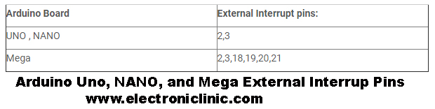
External Interrupts:
The number of external interrupts in Arduino Uno and NANO is the same and are available on the same pin numbers 2 and 3. While in Mega we have 6 external interrupts which are assigned to pins 2, 3, 18, 19, 20, and 21. You can clearly see in the following table.
Pin Change Interrupts:
In Atmega328 based Arduino Uno Board or ATmega168 based board, all the I/O pins can be used as the interrupt pins. These interrupts can be enabled by using the Pin Change interrupts. These interrupts can also be triggered using the FALLING or RISING edges.
One more thing that you should know about before I explain the basic circuit diagram and Arduino Programming is the ISR which stands for the Interrupt Service Routine.
What is ISR” Interrupt Service Routine”
The ISR” Interrupt Service Routine” is basically a set of instructions which is executed when an external interrupt occurs. In Arduino Programming these instructions are included in a user-defined function and this function is called each time the external hardware interrupt pin of the Arduino or Mega is triggered. The circuit diagram and Programming that I am going to explain in this tutorial can work with NANO and Mega as well. As I am going to use Pin 2 of the Arduino. This pin is common among all the three boards.
The ISR has the following syntax in Arduino:
attachInterrupt(interrupt,ISR,mode);
we use the attachInterrupt() function for creating the external interrupt. This function has three parameters.
Interrupt:
The number of Interrupt (int). I will be using Pin number 2, so I will simply write 2. As in Arduino interrupt 0 is available on pin number 2 and interrupt 1 is available on pin number 3. In programming, I will use interrupt 0 which is on pin number 2.
ISR:
This is already explained above, this is basically a user-defined function which consists of the instructions that you want to execute when an external hardware interrupt occurs.
Mode:
We have 4 modes which are
- LOW: to trigger the interrupt whenever the pin is low
- CHANGE: to trigger the interrupt whenever the pin changes the value
- RISING: to trigger when the pin goes from low to high
- FALLING: when the pin goes from high to low.
Note: There are things that you need to take care of which are, no delays should be used inside the ISR and keep the code as short as possible.
Practical use of Hardware Interrupts:
To keep things simple and straight forward I am going to use two LEDs and a push-button. One LED will turn on and turn off at a regular interval of 1 second, while the other LED will remain OFF. When the push button is pressed an interrupt will be generated which will stop the blinking LED and the other LED will turn ON forever. We can think of this as a security system the LED which is blinking represents the normal situation. When the button is pressed “let’s say an intruder stepped on the button” another LED will turn ON which indicates a buzzer. Later this button can be replaced with an Infrared IR sensor and the LED can be replaced with the buzzer or light bulb.
As this is a small tutorial for this we can use the Proteus simulation. You can also download the Proteus simulation by clicking on the download button below.
Download Arduino Hardware Interrupts:
Proteus Simulation: proteus simulation of interrupt
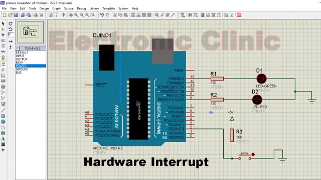
As you can see the circuit diagram is really simple. This circuit is enough for me to explain how the external hardware interrupts are used. As you can see a push-button is connected with pin number 2 of the Arduino which is interrupt 0.
Two LEDs are connected with pin number 8 and pin number 13. The anode sides of the LEDs are connected with the Arduino Pins while the cathode sides are connected with the ground. In a normal situation, the LED which is connected with pin number 13 will continue to blink at a regular interval of 1 second.
When the push button has pressed the LED which is connected with pin number 13 will stop blinking and the other LED which is connected with pin number 8 will turn ON forever until we restart/reset the Arduino. Now it’s time to start the programming.
Arduino Hardware Interrupt Programming:
|
1 2 3 4 5 6 7 8 9 10 11 12 13 14 15 16 17 18 19 20 21 22 23 24 25 26 27 28 29 |
int led1 = 8; int led2 = 13; void setup() { pinMode(led1, OUTPUT); pinMode(led2, OUTPUT); digitalWrite(led1, LOW); digitalWrite(led2, LOW); attachInterrupt(0, ISR1, FALLING); } void loop() { digitalWrite(led2, HIGH); delay(1000); digitalWrite(led2, LOW); delay(1000); } void ISR1() { digitalWrite(led2,LOW); while(1) { digitalWrite(led1, HIGH); } } |
Arduino Hardware interrupts Program explanation:
As you can see the program is really simple. I started off by defining pins for the two LEDs. The green LED is connected with pin number 13 while the RED LED is connected with pin number 8. There is no need for defining a pin for the push button.
int led1 = 8;
int led2 = 13;
Every Arduino and Mega program has at least two functions which are the void setup and void loop functions. Void means that these programs are not returning any values while the empty parenthesis means that these functions are not taking any arguments as the input. The void setup function executes only one time. While the void loop function executes infinite times until we reset the Arduino or Mega.
void setup()
{
pinMode(led1, OUTPUT);
pinMode(led2, OUTPUT);
the two LEDs are set to output using the pinMode function.
digitalWrite(led1, LOW);
digitalWrite(led2, LOW);
Both the LEDs are turned OFF using the digitalWrite function.
To enable the interrupt we use the attachInterrupt function. Its syntax is already explained above. ISR1 is a user-defined function which is executed with the pin 2 of the Arduino is triggered.
attachInterrupt(0, ISR1, FALLING);
}
void loop()
{
The following set of instructions turns ON and turns OFF the led at a regular interval of 1 second, as 1000 milliseconds are equal to 1 second.
digitalWrite(led2, HIGH);
delay(1000);
digitalWrite(led2, LOW);
delay(1000);
}
The ISR1 is a user-defined function which does not return any value and does not take any argument as the input.
void ISR1()
{
First, we turn off the GREEN LED, and then we use an infinite loop and turn on the RED LED.
You can replace this code with any set of instructions as per your requirement.
digitalWrite(led2,LOW);
while(1)
{
digitalWrite(led1, HIGH);
}
}
After the programming is done, first compile the code to generate the hex file. Then copy the link and paste it into the Proteus simulation. Watch the following video.
Arduino Hardware Interrupts Demonstration Video:
Discover more from Electronic Clinic
Subscribe to get the latest posts sent to your email.


