Arduino PWM: Control Led Brightness using Potentiometer Code Example
Last Updated on August 16, 2024 by Engr. Shahzada Fahad
Table of Contents
Arduino PWM:
In this example, I am going to explain how to control the brightness of an LED using a potentiometer. For this example, you can use any PWM pin on the Arduino. In my case, I am using the digital pin 5 which is also a PWM pin. Let me explain the connections.
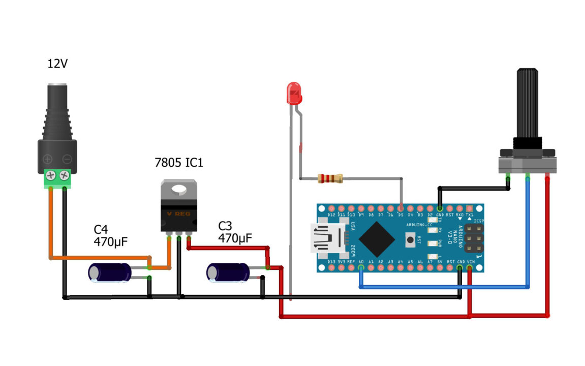
Potentiometer is still connected to the Analog Pin A0, I explained this in example #4, and the LED is connected to Pin5 through this 330 ohm currently limiting resistor. Now let’s go ahead and take a look at the programming.
Amazon Links:
Arduino Nano USB-C Type (Recommended)
*Disclosure: These are affiliate links. As an Amazon Associate I earn from qualifying purchases.
Arduino PWM Programming:
|
1 2 3 4 5 6 7 8 9 10 11 12 13 14 15 |
int ledPin = 5; // LED connected to digital pin 5 which is also a PWM pin. int analogPin = A0; // Potentiometer is connected to the analog pin A0 int val = 0; // variable to store to potentiometer value void setup() { pinMode(ledPin, OUTPUT); // sets the pin as output pinMode(analogPin, INPUT); } void loop() { val = analogRead(analogPin); // read the input pin val = map(val, 0, 1023, 0, 255); analogWrite(ledPin, val); // analogWrite values from 0 to 255 } |
I defined the pins and variables using the same rules as I explained in example #1. Anyway, in this example the instructions are pretty much the same except these two instructions.
map() function is a useful function that is used to scale (or map) a value from one range to another. It takes an input value and scales it proportionally to a new range. This function is particularly handy when you want to convert sensor readings or other values to a different scale that is more suitable for your application. You know the duty cycle should be between 0 and 255. So that’s why I converted the Potentiometer value from 0 to 1023 into 0 to 255. You can use the same technique for setting the motor speeds and you can also use this technique for expressing the sensor values in percentage. So, it depends on your logic how you use it.
Unlike the analogRead() function that is used for reading analog values, analogWrite() function is used for generating analog-like output on certain pins. However, it’s important to note that not all pins on the Arduino board supports PWM. On most Arduino boards, the pins that support PWM are marked with this “~” symbol next to the pin number.
The analogWrite() function takes two arguments: the first argument is the pin number you want to generate the PWM signal on, and the second argument is the value of the duty cycle. The duty cycle value should be between 0 (fully off) and 255 (fully on).
After uploading the program you will able to control the LED brightness.
For the step by step explanation and practical demonstration watch the video tutorial given at the end of this article.
video tutorial

Discover more from Electronic Clinic
Subscribe to get the latest posts sent to your email.


