Arduino RPM Counter & DC Motor Constant Speed Controller
Last Updated on August 18, 2024 by Engr. Shahzada Fahad
Table of Contents
Arduino RPM Counter Description:
Arduino RPM Counter & DC Motor Constant Speed Controller- In this tutorial, you will learn how to make an RPM counter and how to automatically adjust the speed of a DC motor. In this project, the IR Sensor will be used with the Arduino Uno for the RPM measurement and a Potentiometer/Variable resistor will be used to set the RPM value. The real-time RPM value will be compared with the preset RPM value and then the Arduino will increase or decrease the speed of the DC motor automatically.
In this tutorial, we will cover,
- The components and tools you will need for this project.
- What is an RPM Counter?
- Why we need DC Motor Constant Speed Controller?
- Complete Circuit Diagram Explanation.
- Proteus Simulation of the RPM Counter & DC Motor Constant Speed Controller.
- Program explanation and finally
- Practical Demonstration of the RPM counter and DC Motor Constant Speed Controller.
Without any further delay, let’s get started!!!
Amazon links
Arduino Nano USB-C Type (Recommended)
*Disclosure: These are affiliate links. As an Amazon Associate I earn from qualifying purchases.
What is an RPM Counter or Tachometer?
RPM stands for “Revolutions per Minute”. The RPM counter is also known as the Tachometer, revolution-counter, tach, rev-counter, and RPM gauge. The RPM counter or Tachometer is an instrument or a device that is used for measuring the rotation speed of a shaft or disk of a motor or any rotating object.
There are two types of Tachometers
- A tachometer that has contact with the rotating object, like for example an Encoder.
- Contact-less tachometer or Optical Tachometers, these types of the tachometer or RPM counters use a laser or Infrared technology for measuring the RPM of a rotating object from a certain distance. The Optical Tachometers are becoming very famous and commonly used in vehicles and machines. The optical tachometers are now commonly used in industries for monitoring the RPM or speed of different AC or DC motors.
In this project, I have used the optical tachometer technology using an IR infrared Sensor.
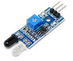
This is an Infrared Sensor. It has two LEDs. The white one is the Transmitter LED while the Black one is the Receiver LED. The range can be adjusted using the variable resistor. The range of detection is also affected by the color of the object, if you place a Black color object the range of detection will decrease and for a White object, the range is increased. To get a nice reflection, use a white color sticky tap on the object surface.
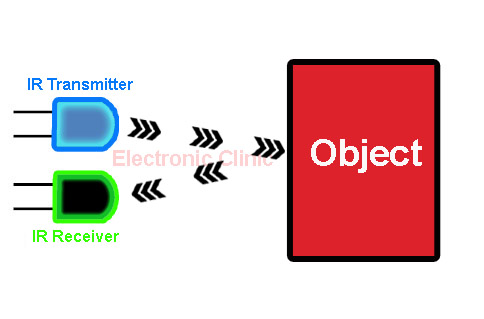
The Transmitted IR rays are reflected by the object and are received by the IR Receiver LED.
Why we need a DC Motor Constant Speed Controller?
DC Motors are used in industrial machines, Electric bikes, Wheelchairs, etc. There are situations when we need to run a DC motor at a constant speed, but sometimes when the load on the DC motor increases the RPM starts to reduce which can really affect the production. In a situation like this, we will need an automatic control system which can automatically adjust the RPM of the DC motor using the Pulse Width Module “PWM” Technique.
To achieve the constant speed or RPM we will need to make an optical tachometer or RPM monitor. The RPM counter or Tachometer will measure the RPM of the DC Motor in Real-Time, this RPM is then compared with the pre-set value defined in the programming and then Arduino decides whether to increase the speed of the dc motor or to decrease the speed. The adjustment value is added or subtracted as per the requirement; this is done automatically by the Arduino Uno.
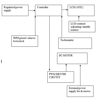
Arduino RPM Counter Block Diagram:
Arduino RPM counter Circuit Diagram:
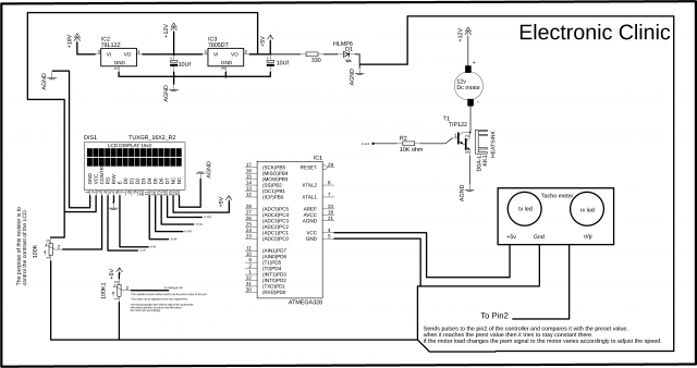
Let’s first of all, start with the Power Supply which is based on the LM7812 and LM7805 Voltage Regulators. The 12 volts from the LM7812 are used to power up the DC Motor, while the LM7805 voltage regulator is used to power up the 16×2 LCD. In the circuit diagram, you can clearly see all the connections where the 5 volts are connected.
The connections of the 16×2 LCD with the Arduino Uno can be clearly seen. Pin number1 and Pin number16 are connected with the ground. Pin number2 and Pin number 15 are connected with the 5 volts. Pin number3 of the 16×2 LCD is connected with the middle Pin of the variable resistor, this variable resistor is used to control the LCD contrast. While the other two pins of the variable resistor are connected with the 5 volts and GND. The RS Pin of the 16×2 LCD is connected with the Arduino’s Pin number7. Pin number5 which is the R/W pin of the LCD is connected with the ground. The Enable pin of the LCD is connected with Pin number8 of the Arduino Uno. The data pins D4 to D7 of the LCD are connected with the Arduino’s Pins 9, 10, 11, and 12.
There is another variable resistor given at the bottom, its middle Pin is connected with the Arduino’s Analog Pin A0. This variable resistor is used to set the Pre-set value. This variable is used to tell the controller that at which RPM we want to keep the motor speed constant. The real-time RPM is compared with this value.
On the right side, as you can see, the IR Sensor VCC and GND are connected with the Arduino’s 5 volts and ground. While the OUT Pin of the IR Sensor Module is connected with the Arduino’s External Interrupt Pin 2.
The Motor driver circuit is build using TIP122. This transistor is selected due to its ability to handle currents more than 2Amps. A motor is then connected between the +v supply wire and collector of the TIP122 and a 10k ohm resistor is connected at the base of the TIP122 as its BJT a current-controlled device, and another end of the 10k ohm resistor is connected to the PWM pin of the Arduino as per the programming. So that’s all about the Circuit diagram.
Arduino RPM Counter Programming:
|
1 2 3 4 5 6 7 8 9 10 11 12 13 14 15 16 17 18 19 20 21 22 23 24 25 26 27 28 29 30 31 32 33 34 35 36 37 38 39 40 41 42 43 44 45 46 47 48 49 50 51 52 53 54 55 56 57 58 59 60 61 62 63 64 65 66 67 68 69 70 71 72 73 74 75 76 77 78 79 80 81 82 83 84 85 86 87 88 89 90 91 92 93 94 95 96 97 98 99 100 101 102 103 104 105 106 107 108 109 110 111 112 113 114 115 116 |
/* * Optical Tachometer * * Uses an IR LED and IR phototransistor to implement an optical tachometer. * The IR LED is connected to pin 13 and ran continually. * Pin 2 (interrupt 0) is connected across the IR detector. * * */ int sensePin = 0; // this pin will be used to set the frequency by changing the varible resistor. int motorPin = 5; // Motor is connected here int ledPin = 13; // IR TRANSMITTER LED connected to digital pin 13 volatile byte rpmcount; unsigned int rpm; unsigned long timeold; int incmspeed = 25; // default motor speed int rs = 7; int en = 8; int d4 = 9; int d5 = 10; int d6 = 11; int d7 = 12; // include the library code: #include <LiquidCrystal.h> // initialize the library with the numbers of the interface pins LiquidCrystal lcd(rs, en, d4, d5, d6, d7); void rpm_fun() { //Each rotation, this interrupt function is run twice, so take that into consideration for //calculating RPM //Update count rpmcount++; } void setup() { pinMode(sensePin, INPUT); pinMode(motorPin,OUTPUT); lcd.begin(16, 2); // intialise the LCD //Interrupt 0 is digital pin 2, so that is where the IR detector is connected //Triggers on FALLING (change from HIGH to LOW) attachInterrupt(0, rpm_fun, FALLING); //Turn on IR LED pinMode(ledPin, OUTPUT); digitalWrite(ledPin, HIGH); rpmcount = 0; rpm = 0; timeold = 0; } void loop() { int val = analogRead(sensePin); //val stores the frequency value this value will be compared with the rpmcount which is the frequency of the motor. val = map(val, 0, 1023, 0 , 8000); //Update RPM every second delay(1000); //Don't process interrupts during calculations detachInterrupt(0); //Note that this would be 60*1000/(millis() - timeold)*rpmcount if the interrupt //happened once per revolution instead of twice. Other multiples could be used //for multi-bladed propellers or fans rpm = 30*1000/(millis() - timeold)*rpmcount; // thirty means that the motor blade cuts the sensor two times. so its gonna be half. if the motor blade // while 20 means that three propellers are used // cuts it one time then mulitiplied by 60. // rpmcount is all the frequency in Hz. timeold = millis(); rpmcount = 0; //Print out result to lcd lcd.clear(); lcd.print("RPM PSRPM adj"); // PS PRES SET RPM, and adjusting rpm lcd.setCursor(0,1); // second row lcd.print(rpm); lcd.setCursor(6,1); // 10 shows the location lcd.print(val); lcd.setCursor(11,1); lcd.print(incmspeed); // Serial.println("Frequency:"); //Serial.println(rpmcount); //Restart the interrupt processing attachInterrupt(0, rpm_fun, FALLING); // once the val value set then it will remain constant. // the val value will be compared with the rpmcount. if the rpmcount is less than the val value. // the voltage to the motor will be inceased to acheive the desired rpmcount. if( rpm < val ) { incmspeed = incmspeed + 10; } if( rpm > val ) { incmspeed = incmspeed - 10; } // new addition if ( incmspeed < 1) { incmspeed = 0; } if( incmspeed > 254) { incmspeed = 255; } // new addition end // int motorspeed = map(val, 0, 1024,0,255); analogWrite(motorPin, incmspeed); } |
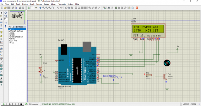
Optical Tachometer or RPM Counter Simulation:
Before I start the soldering I always check my connections in simulation software like Proteus, and once I am satisfied with the results then I start the practical connections.
Download Simulation of Arduino RPM counter & DC Motor Constant Speed Controller: simulation
For the practical demonstration watch video given below. This is an old video which I recorded a long time ago, sorry for the video quality. The same project is also known as the frequency locked loop DC Motor Speed Controller.
Arduino RPM Counter Video Tutorial:
Discover more from Electronic Clinic
Subscribe to get the latest posts sent to your email.


It’s a great effort you are helping students. I’m trying to find hex file simulation plz guide me in this regard.
Hello. I’ve been trying to use your code but instead of using an Infrared sensor I want to use a Hall Effect sensor. I don’t know where I’m going wrong?
int sensePin = 2; // hall effect sensor
int motorPin = 9; // Motor is connected here
volatile byte rpmcount;
unsigned int rpm;
unsigned long timeold;
int incmspeed = 25; // default motor speed
byte val = 1500;
void rpm_fun()
{
rpmcount++;
}
void setup()
{
pinMode(sensePin, INPUT);
pinMode(motorPin,OUTPUT);
attachInterrupt(0, rpm_fun, FALLING);
rpmcount = 0;
rpm = 0;
timeold = 0;
}
void loop()
{
delay(1000);
detachInterrupt(0);
rpm = 601000/(millis() – timeold)rpmcount; // thirty means that the motor blade cuts the sensor two times. so its gonna be half. if the motor blade
timeold = millis();
rpmcount = 0;
attachInterrupt(0, rpm_fun, FALLING);
if( rpm < val )
{
incmspeed = incmspeed + 10;
}
{
incmspeed = incmspeed – 10;
}
// new addition
if ( incmspeed < 1)
{
incmspeed = 0;
}
if( incmspeed > 254)
{
incmspeed = 255;
}
analogWrite(motorPin, incmspeed);
Serial.print(rpm);
}
Thanks for this, extremely helpful!!
Andre..
Without going into your code, have you used a pull-up resistor to 5V? you will need to with most Hall effect FG outputs.
Cheers
I also used it but in simulation animation the motor is not rotating
Dear Mr Engr Fahad
is it possible to have PR RPM fixed 5 different frequency example 100, 200, 300, 400 & 500rpm with normal rotary switch for rpm selection
Thanking You
Hello,
What was meant my:
int incmspeed = 25; // default motor speed
What is the “default motor speed?
Also you’re powering the IR LED from pin 13 but using the sensor from doesn’t need that because it’s always on.
I tried “the project and it produces extremely high RPMs. For example a 40x40mm fan with a reflector on only one of the blades will produce 45-60 000 RPMs while according to the datasheet it;s a 7000rpm fan. Had to use smaller multiplication by 1000 in order to get in the ballpark but some comments on that will be appreciated as well.
The sensor is too sensitive and doesn’t work accurately at small distances and on small diameter rotors.