Arduino SSD1306 Oled Display Module- Circuit diagram and Programming
Last Updated on August 16, 2024 by Engr. Shahzada Fahad
Table of Contents
Arduino Oled Display, Example:
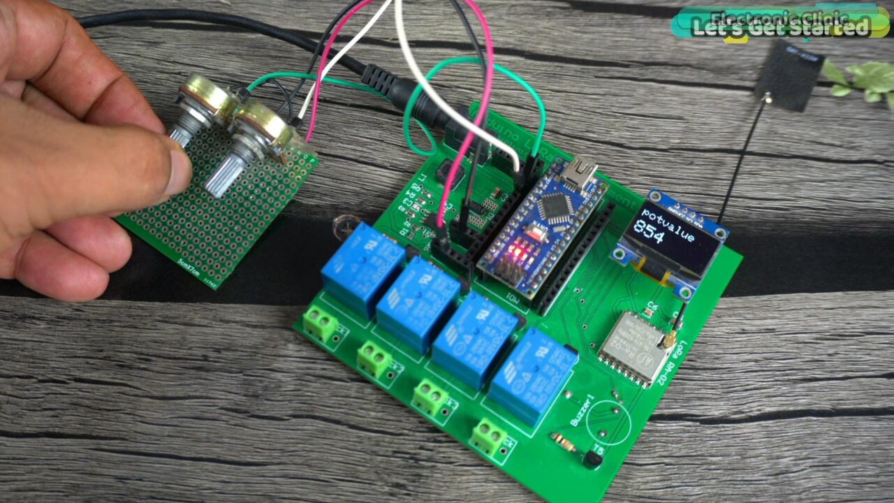
In this example, I am going to explain how to use an I2C-supported SSD1306 Oled display module with the Arduino. For the demonstration purposes, I am going to print the Potentiometer value on the Oled display module.
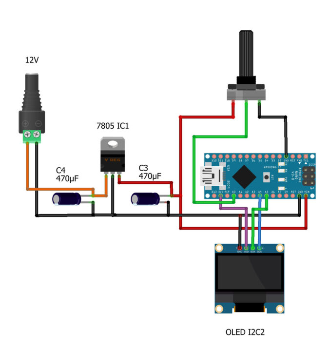
Potentiometer is still connected to the analog pin A0. The VCC and GND of the Oled display module are connected to the Arduino 3.3V and GND pins. Whereas the SDA and SCL pins of the Oled display Module are connected to the Arduino Analog pins A4 and A5 respectively. A4 is the SDA and A5 is the SCL. Now, let’s go ahead and take a look at the programming.
Amazon Links:
Arduino Nano USB-C Type (Recommended)
*Disclosure: These are affiliate links. As an Amazon Associate I earn from qualifying purchases.
Arduino Oled Display Library Installation:
For the SSD1306 Oled display module first you will need to install the libraries and then you can use the header files. For this simply go to the Sketch Menu, then to Include Library and click on the manage libraries. Type Adafruit_GFX in the search box and install it.
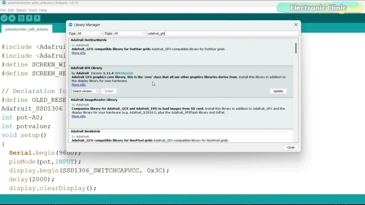
As you can see I have already installed this library. Next, search for the Adafruit_SSD1306 and install it.
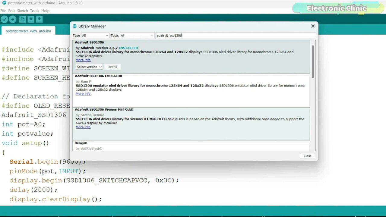
As you can see I have also installed this library.
Arduino Oled Display Programming:
|
1 2 3 4 5 6 7 8 9 10 11 12 13 14 15 16 17 18 19 20 21 22 23 24 25 26 27 28 29 30 31 32 33 34 35 |
#include <Adafruit_GFX.h> #include <Adafruit_SSD1306.h> #define SCREEN_WIDTH 128 // OLED display width, in pixels #define SCREEN_HEIGHT 64 // OLED display height, in pixels // Declaration for an SSD1306 display connected to I2C (SDA, SCL pins) #define OLED_RESET -1 // Reset pin # (or -1 if sharing Arduino reset pin) Adafruit_SSD1306 display(SCREEN_WIDTH, SCREEN_HEIGHT, &Wire, OLED_RESET); int pot=A0; int potvalue; void setup() { Serial.begin(9600); pinMode(pot,INPUT); display.begin(SSD1306_SWITCHCAPVCC, 0x3C); delay(2000); display.clearDisplay(); display.setTextColor(WHITE); delay(10); } void loop() { potvalue=analogRead(pot); display.clearDisplay(); display.setTextSize(2); display.setCursor(0, 10); display.print("potvalue"); display.setTextSize(3); display.setCursor(0, 35); display.print(potvalue); display.display(); delay(100); } |
I started off by adding the header files.
Next, I defined the Width and Height of the Oled display module. The type of the Oled display module I am using doesn’t have a reset pin so that’s why the OLED_RESET is set to -1.
Adafruit_SSD1306 display(SCREEN_WIDTH, SCREEN_HEIGHT, &Wire, OLED_RESET);
This line initializes an instance of the Adafruit_SSD1306 class named display. The constructor takes four arguments.
Potentiometer is connected to the Analog pin A0 named as pot and the potvalue variable is going to store the value of the potentiometer.
In the void setup() function, you can see I have activated the Serial communication and this time round I only used it for the debugging purposes. The potentiometer is set as INPUT. This line activates the Oled display module. 0x3C is the I2C address you can use the I2C scanner code to find this address. You can download that code from the Article. Anyway, then we clear the display and set the text color to white.
In the void loop() function, we simply read the Potentiometer and store its value in the variable potvlaue and then using these instructions we print this text and value on the Oled display Module. You can set the font size, and using the setCursor you can select any position, and using the display.print() function you can print strings and numbers on the Oled display module.
video tutorial
Discover more from Electronic Clinic
Subscribe to get the latest posts sent to your email.


