Arduino Water Pressure Sensor Project, Water Level Pressure Sensor
Last Updated on September 21, 2024 by Engr. Shahzada Fahad
Table of Contents
Arduino Water Pressure Sensor, Description:
Arduino Water Pressure Sensor Project, Water Level Pressure Sensor- Recently I got this water pressure sensor from DFRobot; which I am going to use with Arduino Nano. You can also use this sensor for measuring Gas pressure. In this tutorial, I will only use this sensor for water detection, and for measuring the water pressure, and for measuring the water level inside a water tank. Using this Water Pressure Sensor you can build yourself a smart water control system using Arduino, Oled display Module, and some LEDs.
You can also watch my video on IoT based Water level monitoring and automatic water pump control system using the ESP32 WiFi + Bluetooth Module, Waterproof Ultrasonic Sensor, and the New Blynk V2.0 more…
It has happened to me and my family members many times that when we start the water pump, we often forget because we are busy with other work. And we don’t remember that we have turned the water pump ON, due to which a lot of water is wasted. And obviously, it makes a lot of difference on the electricity bill as well.
So, to avoid this type of situation, I have resorted to this water pressure sensor, by using which I can measure the water pressure inside the pipe. When the water level in the tank changes, then obviously the water pressure inside the pipe will also change. So, if I use Arduino to measure the water pressure, I can easily make a control system for myself, which will alert me when the water tank is empty, or when the water tank is full.
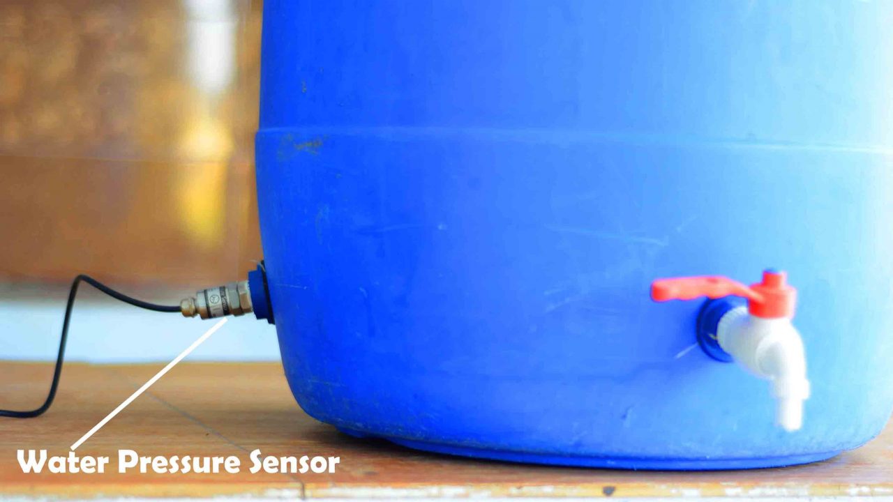
To explain this idea, I have done this basic setup, you can see the water tap and I have also attached the Water pressure sensor. Here, this water storage drum is representing the water tank.
As I am using this Water pressure sensor for the first time, so this tutorial is going to be a kind of a getting started tutorial. And I will try my level best to explain the most basic things including technical specifications, Pinout, it’s interfacing with Arduino, its calibration, final circuit diagram, and final Arduino code. Anyway, first let me share with you the Final test results, and afterward, I will explain everything else.
read my article on Wireless water level indicator “communication range 1.5Km.
I have connected everything as per the circuit diagram, which I will explain in a minute. I have already calibrated the water pressure sensor. You guys don’t need to worry about it. I will explain in detail how you can calibrate this sensor. First, I am going to explain the working and then I will start practical demonstration.
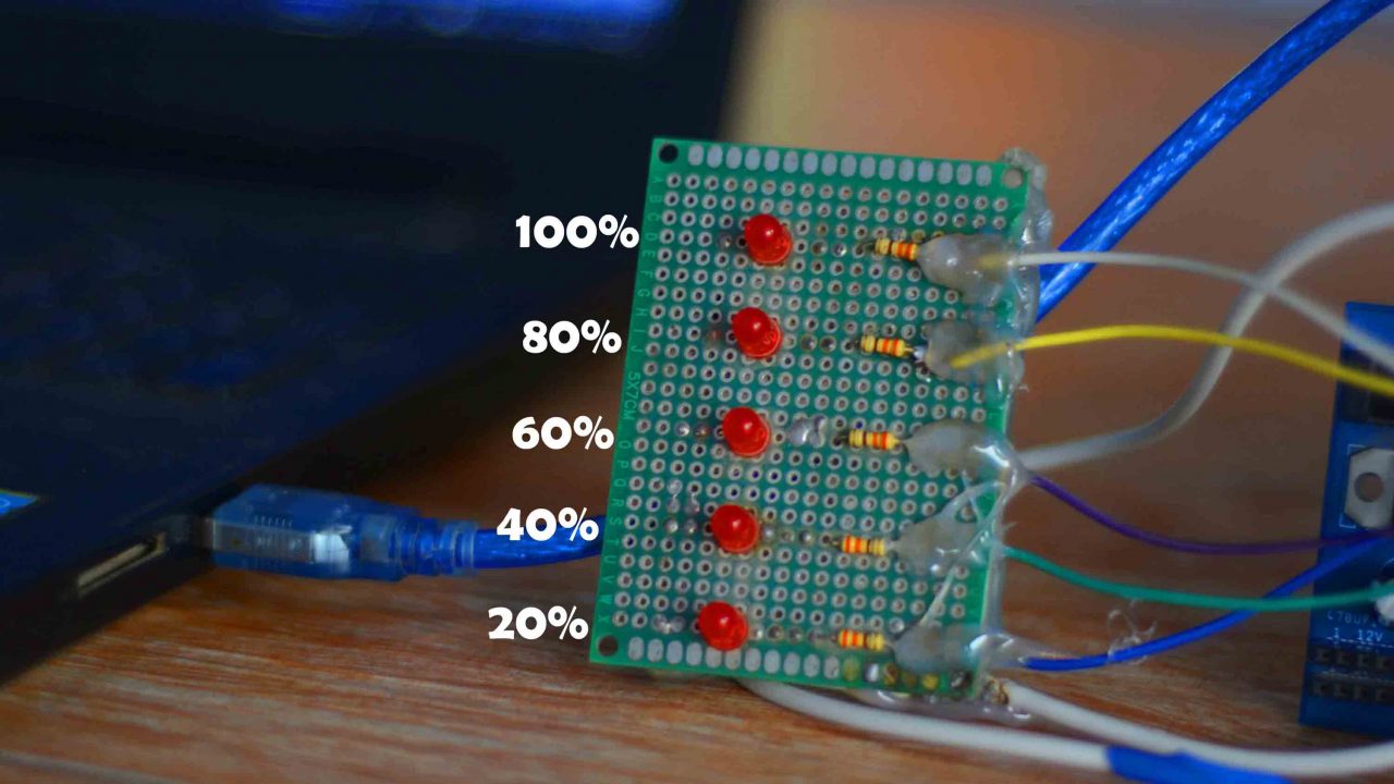
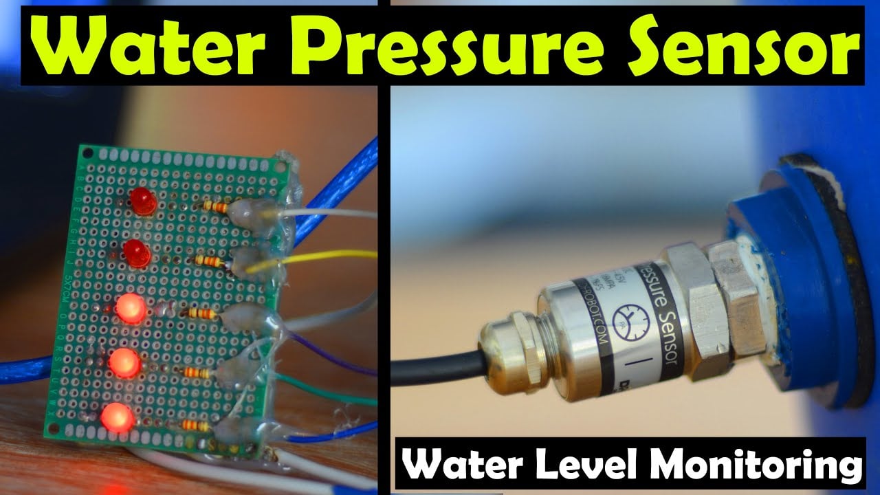
On the Oled display module, I will print the Water Pressure in Kpa “Kilo Pascal”. And the LEDs will show water level. If the first LED is ON it means 20%, similarly the 2nd LED means 40%, 60%, 80%, and the 5th LED represents 100% water level. So, when all the LEDs are ON, it means that the water tank is full. And when all the LEDs are OFF, it means that the water tank is empty. Now let us move ahead and start our practical demonstration.
I have powered up the Arduino. Right now All the LEDs are OFF as the water drum is completely empty. And on the Oled display module you can see value is around 0 Kpa.
I am going to add water and you will see an increase in the pressure value and the LEDs will turn ON one by one as the water level increases.
When the Water Drum completely filled, all the LEDs turn ON. For the practical demonstration watch video tutorial given at the end of this article. I am sure by now, you might have got an idea of how does this system work. So, without any further delay let’s get started!!!
Amazon Links:
Arduino Nano USB-C Type (Recommended)
Water Pressure Sensor from DFRobot
*Disclosure: These are affiliate links. As an Amazon Associate I earn from qualifying purchases.
Water Pressure Sensor:
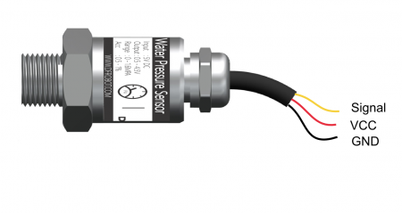
This is the Water pressure sensor from DFRobot. The most important specs are already printed on the sensor itself. It adopts DFRobot Gravity 3-pin interface. The Yellow wire is the analog signal output wire, Red wire is the VCC, and the Black wire is the ground.
| Label | Name | Description |
| Yellow | Signal(Output:0.5~4.5V) | Analog Signal |
| Red | VCC(5VDC) | + |
| Black | GND | – |
Water Pressure Sensor Specifications:
As I said earlier, you can use this sensor for measuring the Liquid or Gas pressure without corrosion. It supports standard 5V voltage input and 0.5 to 4.5V linear voltage output. The recommended pressure measurement range is 0 to 1Mpa but you can use it to measure pressure up to 1.5Mpa. As per the manufacturer, the normal operating pressure should be less than or equal to 2.0 Mpa. Pressure Greater than or equal to 3 Mpa will damage the sensor. The measure accuracy is 0.5% at around 55 degrees Celsius. The waterproofing level is IP68. The Operating temperature is from -20 to 85 degrees Celsius. The Sensor response time is less than 2ms.
- Medium: liquid/gas without corrosion
- Wiring: Gravity-3Pin (Signal-VCC-GND)
- Pressure Measurement Range: 0~1 Mpa
- Input Voltage: +5 VDC
- Output Voltage: 0.5~4.5 V
- Threadably: G1/4
- Adapter: G1/2 to G1/4
- Waterproof Level: IP68
- Operating Temperature: -20~85°C
- Response Time: <2.0 ms
- Quiescent Current: 2.8 mA
- Normal Operating Pressure: ≤2.0 Mpa
- Damaged Pressure: ≥3.0 Mpa
- Service Life: ≥10’000’000 times (10 million)
Features
- Support water pressure detection of living environmental water systems, such as houses, gardens and farms.
- Support water pressure detection of outdoor environment, such as rivers, lakes and sea.
- Support water pressure detection of tanks.
- Support liquid level detection in special situation.
Now, let’s take a look at the circuit diagram.
Pressure Sensor Interfacing with Arduino:
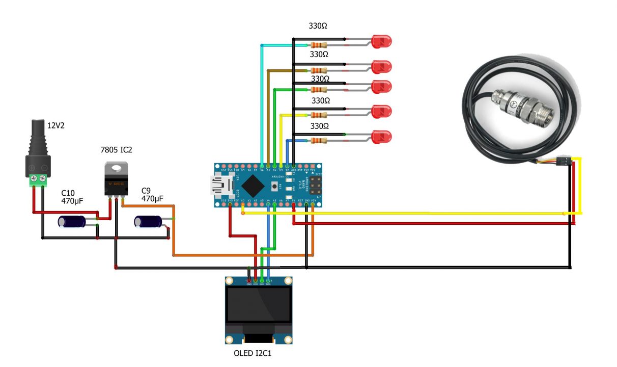
On the Left side is the regulated 5 volts power supply based on the 7805 linear voltage regulator. I am using this regulated 5 volts power supply to power up the Arduino and all the other electronics.
The VDD and GND pins of the SSD1306 Oled display module are connected with the Arduino 3.3V and GND pins. While the SCK or SCL and SDA pins of the Oled display module are connected with the Arduino A5 and A4 pins.
5 LEDs are connected with the digital pins D2, D3, D4, D5, and D6. As these are 2.5V LEDs that’s why I am using 330-ohm current limiting resistors.
The Signal wire which is the Yellow wire on the Water pressure sensor is connected with the A0 pin, the Red wire is connected with 5 volts, and the GND wire is connected with the Arduino ground.
Water Pressure Sensor Calibration:
This water pressure sensor is not Factory calibrated. So, first you will have to calibrate this sensor. Before you start the calibration process, first of all, make sure there is no water or any other liquid inside the Drum or Barrel or Water tank etc.
Next, all you need to do is to download the code given below and upload it to your Arduino. This is the code for the calibration.
Download the following Libraries:
Water Pressure Sensor Calibration Code:
|
1 2 3 4 5 6 7 8 9 10 11 12 13 14 15 16 17 18 19 20 21 22 23 24 25 26 27 28 29 30 31 32 33 34 35 36 37 38 39 40 41 42 43 44 45 46 47 48 49 50 51 52 53 54 55 56 57 58 59 60 61 62 63 64 65 66 67 68 69 70 71 72 73 74 75 76 77 78 79 80 81 82 83 84 |
/************************************************************ Water Sensor Key Parameter - Parts No.:KY-3-5 - Sensing range: 0 - 1 MPa - Input Voltage: 5VDC - Output Voltage: 0.5 - 4.5 VDC (Linearly corresponding to 0 - 1 MPa) - Accuary: 0.5% - 1% FS **************************************************************/ /************************************************************ Water Sensor Calibration The output voltage offset of the sensor is 0.5V (norminal). However, due to the zero-drifting of the internal circuit, the no-load output voltage is not exactly 0.5V. Calibration needs to be carried out as follow. Calibration: connect the 3 pin wire to the Arduio UNO (VCC, GND and Signal) without connecting the sensor to the water pipe and run the program for once. Mark down the LOWEST voltage value through the serial monitor and revise the "OffSet" value to complete the calibration. After the calibration the sensor is ready for measuring! **************************************************************/ #include <Wire.h> #include <Adafruit_GFX.h> #include <Adafruit_SSD1306.h> #define SCREEN_WIDTH 128 // OLED display width, in pixels #define SCREEN_HEIGHT 64 // OLED display height, in pixels #define OLED_RESET -1 // Reset pin # (or -1 if sharing Arduino reset pin) Adafruit_SSD1306 display(SCREEN_WIDTH, SCREEN_HEIGHT, &Wire, OLED_RESET); const float OffSet = 0.254 ; // adjust this value float avgV = 0.0; float V=0; float P; void setup() { Serial.begin(9600); // open serial port, set the baud rate to 9600 bps Serial.println("/** Water pressure sensor demo **/"); Serial.println("/** Water pressure sensor demo **/"); display.begin(SSD1306_SWITCHCAPVCC, 0x3C); delay(2000); display.clearDisplay(); display.setTextColor(WHITE); } void loop() { //Connect sensor to Analog 0 V = analogRead(0) * 5.00 / 1024; //Sensor output voltage P = (V - OffSet) * 250; //Calculate water pressure Serial.print("Voltage:"); Serial.print(V, 3); Serial.println("V"); Serial.print(" Pressure:"); Serial.print(P, 1); Serial.println(" KPa"); Serial.println(); display.clearDisplay(); display.setCursor(25,0); display.setTextSize(1); display.setTextColor(WHITE); display.println(" Caliberation"); display.setCursor(10,20); display.setTextSize(2); display.print("P:"+String(P)); display.print("KPa"); display.setCursor(10,45); display.setTextSize(2); display.print("V: "); display.print(V); display.display(); delay(1000); } |
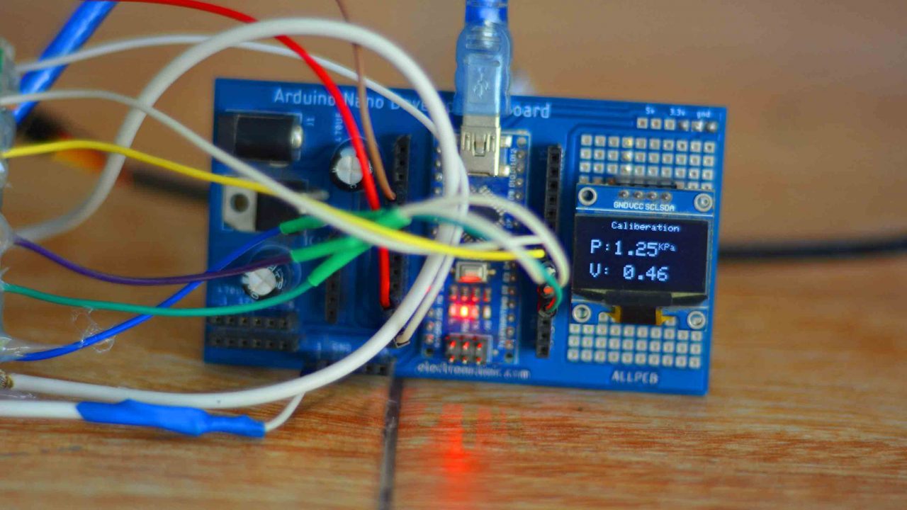
On the Oled display, you can see the pressure in Kpa and the voltage.
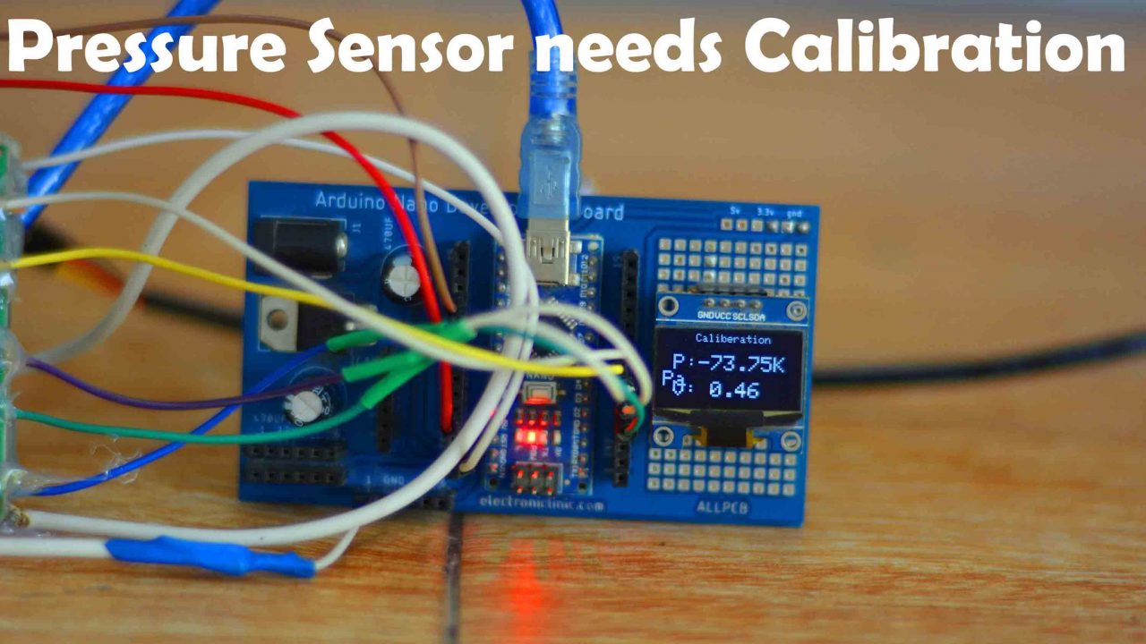

As per the table when the voltage is 0.5V the pressure should be 0.0Kpa. But as you can see on the display, the pressure value is wrong, which means we will have to adjust the Offset value in the Arduino code. Keep on changing the offset value until you get a value that is around 0.0 Kpa. Don’t worry if you see very small fluctuations, you can see the voltage is not perfectly 0.5 volts and also this sensor has 0.5% accuracy.
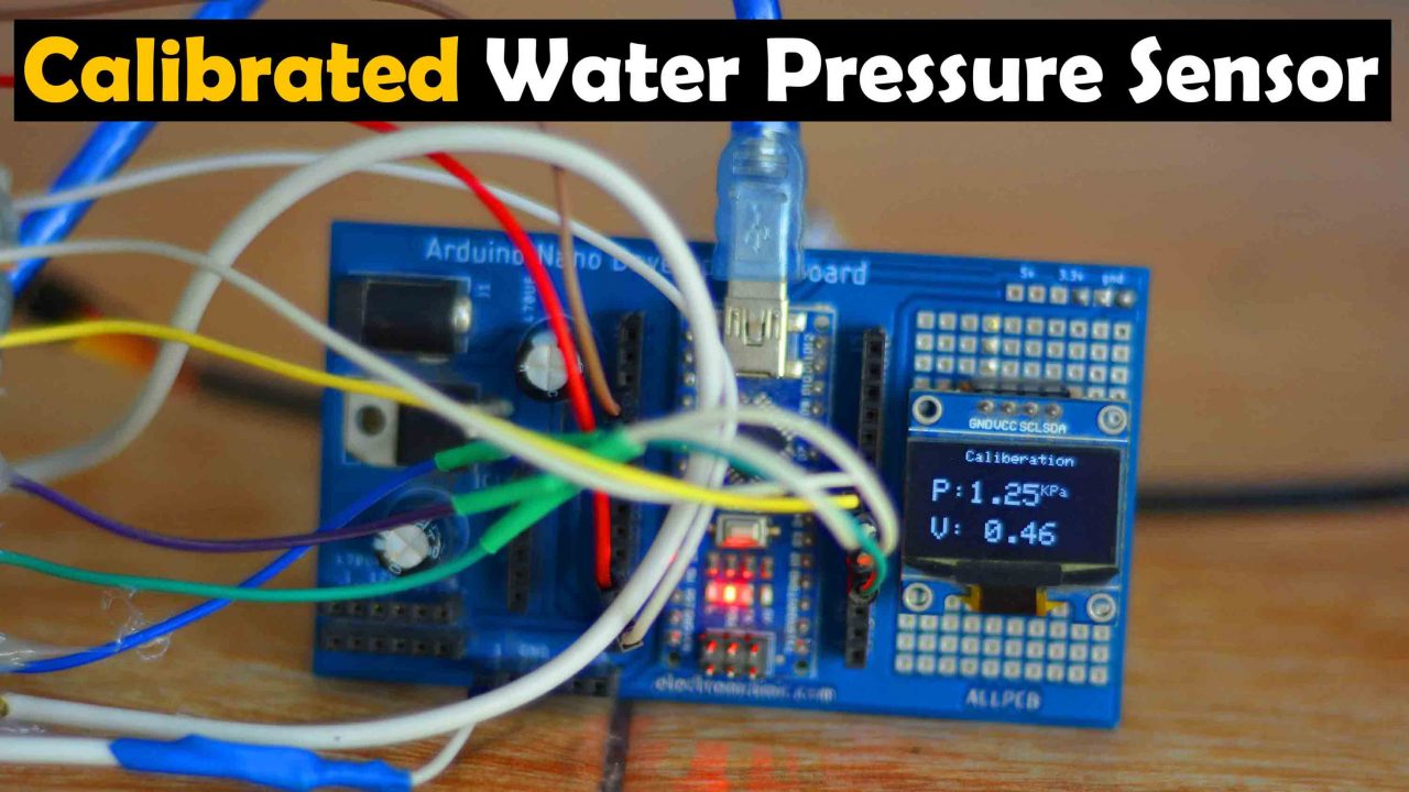
In my case, I am happy with this offset value of 0.545. So I will use this value in my final code.
Now, I am going to fill the Drum with water so that I can find the maximum value of Water pressure, as I will need this for the programming to define the range. So, when I filled the drum the Kpa value was around 112.
Water Pressure Sensor Arduino Programming:
|
1 2 3 4 5 6 7 8 9 10 11 12 13 14 15 16 17 18 19 20 21 22 23 24 25 26 27 28 29 30 31 32 33 34 35 36 37 38 39 40 41 42 43 44 45 46 47 48 49 50 51 52 53 54 55 56 57 58 59 60 61 62 63 64 65 66 67 68 69 70 71 72 73 74 75 76 77 78 79 80 81 82 83 84 85 86 87 88 89 90 91 92 93 94 95 96 97 98 99 100 101 102 103 104 105 106 107 108 109 110 111 112 113 114 115 116 117 118 119 120 121 122 123 124 125 126 127 128 129 130 131 132 133 134 135 136 137 138 139 140 141 142 143 144 145 146 147 148 149 150 |
/************************************************************ Water Sensor Key Parameter - Parts No.:KY-3-5 - Sensing range: 0 - 1 MPa - InPut Voltage: 5VDC - OutPut Voltage: 0.5 - 4.5 VDC (Linearly corresPonding to 0 - 1 MPa) - Accuary: 0.5% - 1% FS **************************************************************/ /************************************************************ Water Sensor Calibration The outPut voltage offset of the sensor is 0.5V (norminal). However, due to the zero-drifting of the internal circuit, the no-load outPut voltage is not exactly 0.5V. Calibration needs to be carried out as follow. Calibration: connect the 3 Pin wire to the Arduio UNO (VCC, GND and Signal) without connecting the sensor to the water PiPe and run the Program for once. Mark down the LOWEST voltage value through the serial monitor and revise the "OffSet" value to complete the calibration. After the calibration the sensor is ready for measuring! **************************************************************/ #include <Wire.h> #include <Adafruit_GFX.h> #include <Adafruit_SSD1306.h> #define SCREEN_WIDTH 128 // OLED display width, in pixels #define SCREEN_HEIGHT 64 // OLED display height, in pixels #define OLED_RESET -1 // Reset pin # (or -1 if sharing Arduino reset pin) Adafruit_SSD1306 display(SCREEN_WIDTH, SCREEN_HEIGHT, &Wire, OLED_RESET); const float OffSet = 0.454 ; int psensor=A0; int led1 = 2; int led2 = 3; int led3 = 4; int led4 = 5; int led5 = 6; float V, P; void setup() { Serial.begin(9600); // open serial port, set the baud rate to 9600 bps pinMode(psensor,INPUT); pinMode(led1, OUTPUT); pinMode(led2, OUTPUT); pinMode(led3, OUTPUT); pinMode(led4, OUTPUT); pinMode(led5, OUTPUT); digitalWrite(led1, LOW); digitalWrite(led2, LOW); digitalWrite(led3, LOW); digitalWrite(led4, LOW); digitalWrite(led5, LOW); Serial.println("/** Water pressure sensor demo **/"); display.begin(SSD1306_SWITCHCAPVCC, 0x3C); delay(2000); display.clearDisplay(); display.setTextColor(WHITE); } void loop() { //Connect sensor to Analog 0 V = analogRead(psensor) * 5.00 / 1024; //Sensor output voltage P = (V - OffSet) * 250; //Calculate water pressure Serial.print("Voltage:"); Serial.print(V, 3); Serial.println("V"); Serial.print(" Pressure:"); Serial.print(P, 1); Serial.println(" KPa"); Serial.println(); display.clearDisplay(); display.setCursor(10,0); display.setTextSize(2); display.setTextColor(WHITE); display.print("Value:"); display.setCursor(10,30); display.setTextSize(2); display.print(P); display.print("KPa"); display.display(); // total pressure when the water drum is completely filled = 112kpa // but i am going to consider it as 100Kpa if( (P > 0) && (P<=10) ) { digitalWrite(led1, LOW); digitalWrite(led2, LOW); digitalWrite(led3, LOW); digitalWrite(led4, LOW); digitalWrite(led5, LOW); } else if( (P > 10) && ( P <= 20) ) { digitalWrite(led1, HIGH); digitalWrite(led2, LOW); digitalWrite(led3, LOW); digitalWrite(led4, LOW); digitalWrite(led5, LOW); } else if( (P > 20) && (P <= 40) ) { digitalWrite(led1, HIGH); digitalWrite(led2, HIGH ); digitalWrite(led3, LOW); digitalWrite(led4, LOW); digitalWrite(led5, LOW); } else if( (P> 40) && (P <= 60) ) { digitalWrite(led1, HIGH); digitalWrite(led2, HIGH ); digitalWrite(led3, HIGH); digitalWrite(led4, LOW); digitalWrite(led5, LOW); } else if( (P > 60) && (P <= 80) ) { digitalWrite(led1, HIGH); digitalWrite(led2, HIGH ); digitalWrite(led3, HIGH); digitalWrite(led4, HIGH); digitalWrite(led5, LOW); } else if( P >= 95 ) { digitalWrite(led1, HIGH); digitalWrite(led2, HIGH); digitalWrite(led3,HIGH); digitalWrite(led4, HIGH); digitalWrite(led5, HIGH); } delay(100); } |
If you are planning on using the SSD1306 Oled display module then you will need Adafruit_GFX and Adafruit_SS1306 libraries. The download links I have already shared above.
Here is the offset value which I found using the hit and trail technique.
The water pressure sensor is connected with the Analog pin A0.
5 LEDs are connected with Arduino pins 2, 3, 4, 5, and 6.
I also defined two variables for storing the Voltage and Pressure values.
Rest of the code is self-explanatory, we are reading the voltage on the Analog pin A0.
Next, we find the pressure and then display the corresponding values on the Oled display module.
Next, as per the minimum and maximum pressure values I am controlling all the 5 LEDs. So, that’s all about the programming.
Consider subscribing my YouTube channel, if you want to see Long Range wireless and IoT versions of the same project.
Watch Video Tutorial:
Discover more from Electronic Clinic
Subscribe to get the latest posts sent to your email.


hi what hight in water was yor tank in yor example 112kpa would equal 1142 cms of water this doesnt seem right
1mpa of pressure wouuld equal 10197.2cms of water
This water pressure sensor Arduino project looks interesting. DIY fans will appreciate the clear directions and available code that make recreating the project a breeze. Sensing water pressure and levels has a number of useful real-world applications. We appreciate you providing us with this in-depth, practical guide.
This Arduino water pressure sensor project is a great solution for monitoring water levels and controlling water pumps efficiently. The tutorial provides clear instructions on using the sensor for water detection, measuring water pressure, and monitoring water levels in a tank. The addition of an OLED display module and LEDs allows for a smart water control system. This project is not only practical but also helps conserve water and reduce electricity bills.