ATtiny85 Arduino Getting Started Tutorial, The Smallest Arduino
Last Updated on September 21, 2024 by Engr. Shahzada Fahad
Table of Contents
Attiny85 Arduino:
ATtiny85 Arduino Getting Started Tutorial, The Smallest Arduino- I am sure you already know about Arduino Uno and Arduino Nano as these are the most commonly used Arduino boards. And I am sure the majority of you guys might also know about other Arduino boards, like Arduino Mega, Arduino Pro Mini, and Arduino Leonardo, etc; there is a long list of the Arduino boards. There are so many other Arduino boards that are not available in the Arduino boards list like the Seeeduino Xiao which is considered to be the smallest Arduino.

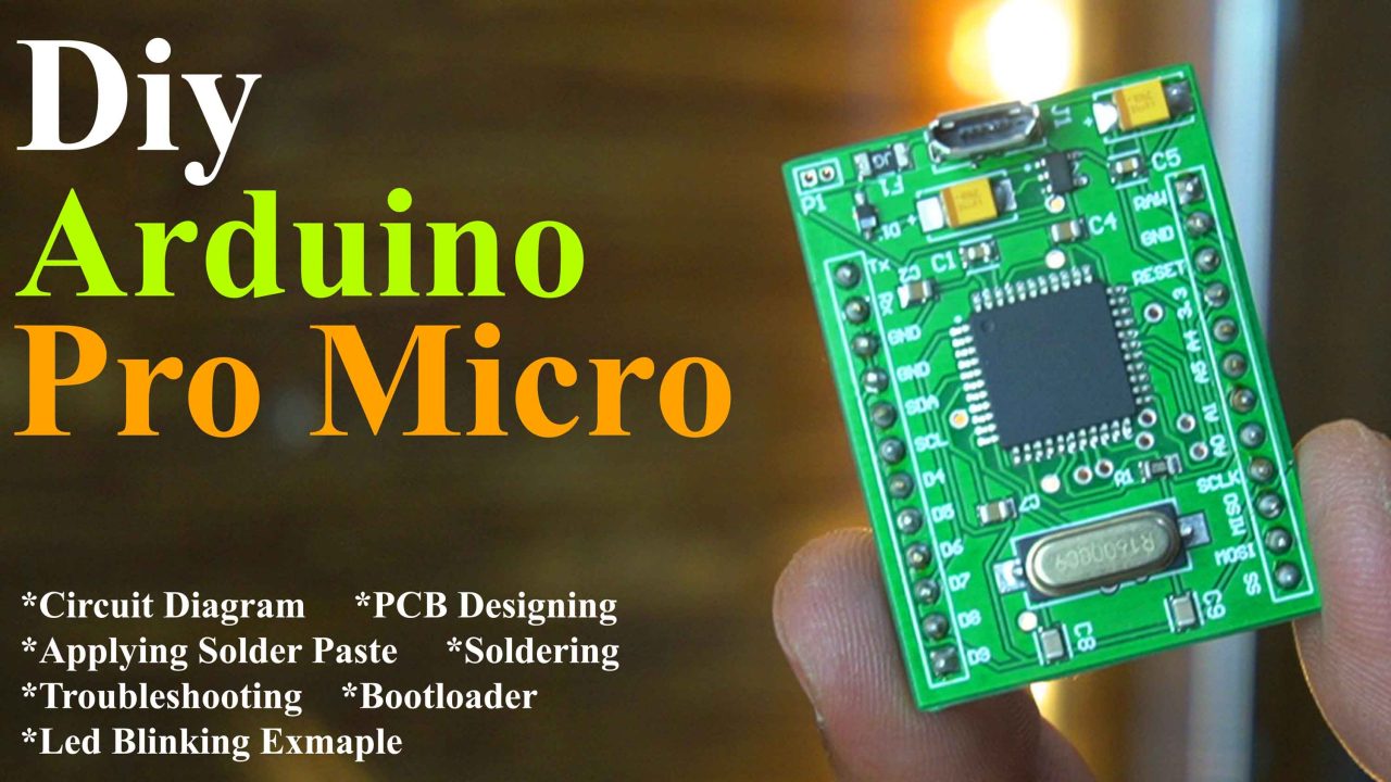
And here is my designed Arduino Pro Micro.
Well I could make it much smaller than the Seeeduino Xiao but, I had to make it slightly bigger for you guys, so that you could easily make it at your home.
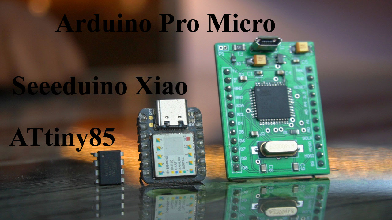
Anyway, I want the smallest Arduino even smaller than the Seeeduino Xiao and Arduino Pro Micro. So, I decided to use the ATtiny85 CMOS 8-bit microcontroller as the smallest Arduino. You can clearly see the size difference. We don’t need to add external capacitors, resistors, and a crystal. And it’s going to be the cheapest micro version of the Arduino.
By looking at its size, you might have an idea that it has fewer IO pins, lower speed, less memory, and no USB interface. So, let me tell you beforehand that you cannot create every project with ATtiny85 that you can create using Arduino Uno, Arduino Nano, or Arduino Pro Micro. However, you can still create thousands of projects using ATtiny85.
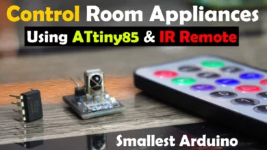
There are many projects in which you only need to connect 1 or 2 sensors along with a display. Or you may want to control certain loads using an IR remote, an RFID module, or other similar devices. ATtiny85 has digital pins, analog pins, PWM pins, SPI pins, and more. Therefore, you can use the ATtiny85 microcontroller board in more than a million different ways. So, without any further delay let’s get started!!!
Amazon Links:
Arduino Nano USB C type (Recommended)
*Disclosure: These are affiliate links. As an Amazon Associate I earn from qualifying purchases.
ATtiny85 Technical Specifications:
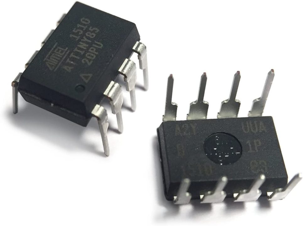
The ATtiny85 is a low-power, high-performance CMOS 8-bit AVR Microcontroller chip developed by Atmel Corporation, and is often used in small and low-power embedded systems. Let’s go through some of its technical specifications.
Key Parameters
Architecture: AVR(Advanced Virtual RISC)
Power Supply voltage: 2.7V to 5.5V
CPU Speed: Up to 20 Mhz
Flash Memory: 8 Kbytes
EEPROM: 512 Bytes
GPIO Pins: 6
Analog Pins: 4
PWM Channels: 2
Interface: USI (Universal Serial Interface)
Operating Temperature Range: -40C to +85C
USB interface: No
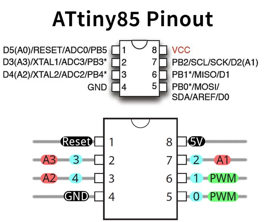
The Architecture is AVR (Advanced Virtual RISC). The power supply voltage is from 2.7V to 5.5V. CPU Speed is up to 20 Mhz. Flash Memory is 8 Kbytes. EEPROM is 512 Bytes. GPIO pins are 6. Analog pins are 4. PWM pins are basically two located on pins 0 and 1. But pin 4 can also be used as PWM pin. So, technically you can say it has 3 PWM pins. The interface type is USI (Universal Serial Interface) which can be configured to perform SPI or I2C communications. The temperature Range is from -40C to +85C. And it has no USB interface.
The ATtiny25/45/85 provides the following features: 2/4/8K byte of In-System Programmable Flash, 128/256/512 bytes EEPROM, 128/256/256 bytes SRAM, 6 general purpose I/O lines, 32general purpose working registers, one 8-bit Timer/Counter with compare modes, one 8-bit high speed Timer/Counter, Universal Serial Interface, Internal and External Interrupts, a 4-channel,10-bit ADC, a programmable Watchdog Timer with internal Oscillator, and three software select-able power saving modes. The Idle mode stops the CPU while allowing the SRAM, Timer/Counter, ADC, Analog Comparator, and Interrupt system to continue functioning. The Power-down mode saves the register contents, disabling all chip functions until the next Interrupt or Hardware Reset. The ADC Noise Reduction mode stops the CPU and all I/O modules except ADC, to minimize switching noise during ADC conversions. The device is manufactured using Atmel’s high density non-volatile memory technology. The On-chip ISP Flash allows the Program memory to be re-programmed In-System through an SPI serial interface, by a conventional non-volatile memory programmer or by an On-chip boot code running on the AVR core.
ATtiny85 Pinout:
You can follow these Pinout diagrams.
Now, we are going to get it ready; So that we can program it using the Arduino IDE. And for this, we will have to Burn the Bootloader. So, let’s go ahead and do it.
ATtiny85 Bootloader Setup:
To burn the Bootloader on the ATtiny85 microcontroller you will need to follow these connections.
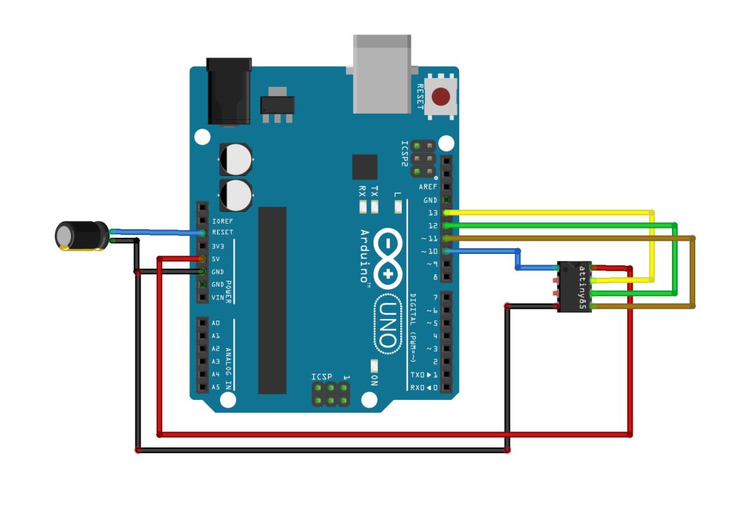
- Connect pin 1 of the ATtiny85 which is also the reset pin to pin 10 of the Arduino which is the SS (Slave Select).
- Connect pin 4 which is the ground pin to the Ground pin of the Arduino.
- Connect pin 5 which is the MOSI pin to pin 11 of the Arduino which is the MOSI (Master-out, Slave In).
- Connect pin 6 which is the MISO pin to pin 12 of the Arduino which is the MISO (Maser-In, Slave Out).
- Connect pin 7 which is the SCK pin to pin 13 of the Arduino which is the SCK (Serial Clock).
- Connect pin 8 of the ATtiny85 which is the VCC pin to the Arduino 5V pin.
- Finally, connect a 10uF capacitor between the Reset and GND pins of the Arduino. Make sure you connect the +Ve leg of the capacitor with the Reset pin and the other leg of the capacitor with the GND. So, that’s all about the connections.
Now, let’s go ahead and start with the Arduino IDE.
ATtiny85 in Arduino IDE:
The ATtiny85 microcontroller is not pre-installed in the Arduino IDE and you can confirm this by going to the Tools Menu and then to board, you will see a long list of the Arduino boards, but you won’t find ATtiny85. So, this means you will have to manually install the ATtiny85 as a board in the Arduino IDE.
For this, copy the board manager URL link given below.
https://raw.githubusercontent.com/damellis/attiny/ide-1.6.x-boards-manager/package_damellis_attiny_index.json
Then come back to the Arduino IDE, go to the File Menu, and then to Preferences, and paste the link in the Additional Boards Manager URLs.

Put a comma if you have added other boards otherwise you can directly paste the board URL link and then click on the OK button.
Go to the Tools Menu, then to board, and click on the Boards Manager. Search for the ATtiny and install it.
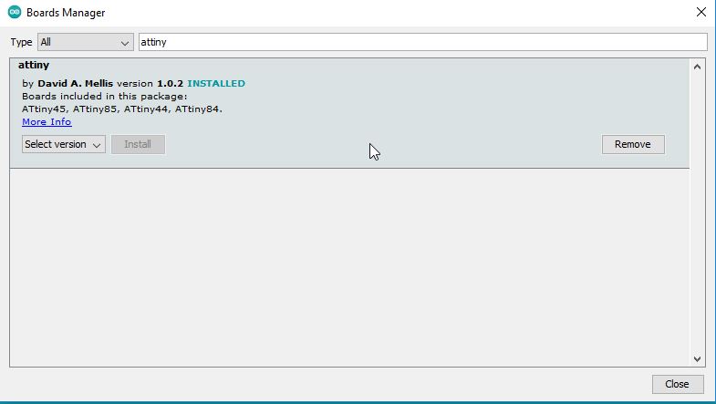
You can see the ATtiny85 is included in this boards Package. Anyway, you can see I have already installed this board.
Now, to confirm that the ATtiny85 Microcontroller is added, go to the Tools Menu, then to Board and you can see the ATtinny Microcontrollers.
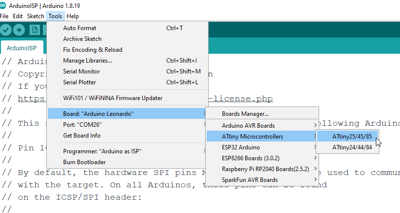
You can see different variants of the ATtiny microcontrollers. So, let’s go ahead and select the ATtiny85 controller. So, our setup on the Arduino IDE is completed.
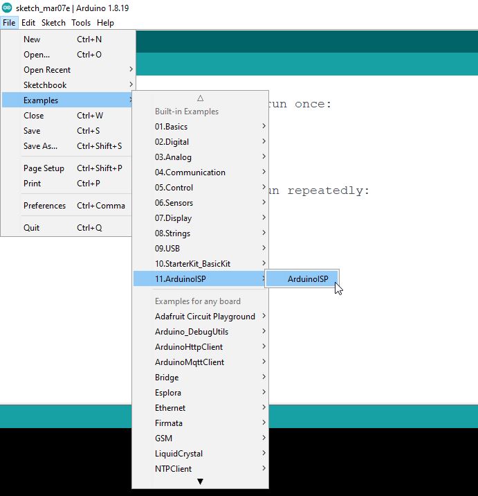
Next, we are going to connect Arduino Uno with the Laptop. While the Arduino IDE is open, go to the File Menu, then to Examples, and open the ArduinoISP.
|
1 2 3 4 5 6 7 8 9 10 11 12 13 14 15 16 17 18 19 20 21 22 23 24 25 26 27 28 29 30 31 32 33 34 35 36 37 38 39 40 41 42 43 44 45 46 47 48 49 50 51 52 53 54 55 56 57 58 59 60 61 62 63 64 65 66 67 68 69 70 71 72 73 74 75 76 77 78 79 80 81 82 83 84 85 86 87 88 89 90 91 92 93 94 95 96 97 98 99 100 101 102 103 104 105 106 107 108 109 110 111 112 113 114 115 116 117 118 119 120 121 122 123 124 125 126 127 128 129 130 131 132 133 134 135 136 137 138 139 140 141 142 143 144 145 146 147 148 149 150 151 152 153 154 155 156 157 158 159 160 161 162 163 164 165 166 167 168 169 170 171 172 173 174 175 176 177 178 179 180 181 182 183 184 185 186 187 188 189 190 191 192 193 194 195 196 197 198 199 200 201 202 203 204 205 206 207 208 209 210 211 212 213 214 215 216 217 218 219 220 221 222 223 224 225 226 227 228 229 230 231 232 233 234 235 236 237 238 239 240 241 242 243 244 245 246 247 248 249 250 251 252 253 254 255 256 257 258 259 260 261 262 263 264 265 266 267 268 269 270 271 272 273 274 275 276 277 278 279 280 281 282 283 284 285 286 287 288 289 290 291 292 293 294 295 296 297 298 299 300 301 302 303 304 305 306 307 308 309 310 311 312 313 314 315 316 317 318 319 320 321 322 323 324 325 326 327 328 329 330 331 332 333 334 335 336 337 338 339 340 341 342 343 344 345 346 347 348 349 350 351 352 353 354 355 356 357 358 359 360 361 362 363 364 365 366 367 368 369 370 371 372 373 374 375 376 377 378 379 380 381 382 383 384 385 386 387 388 389 390 391 392 393 394 395 396 397 398 399 400 401 402 403 404 405 406 407 408 409 410 411 412 413 414 415 416 417 418 419 420 421 422 423 424 425 426 427 428 429 430 431 432 433 434 435 436 437 438 439 440 441 442 443 444 445 446 447 448 449 450 451 452 453 454 455 456 457 458 459 460 461 462 463 464 465 466 467 468 469 470 471 472 473 474 475 476 477 478 479 480 481 482 483 484 485 486 487 488 489 490 491 492 493 494 495 496 497 498 499 500 501 502 503 504 505 506 507 508 509 510 511 512 513 514 515 516 517 518 519 520 521 522 523 524 525 526 527 528 529 530 531 532 533 534 535 536 537 538 539 540 541 542 543 544 545 546 547 548 549 550 551 552 553 554 555 556 557 558 559 560 561 562 563 564 565 566 567 568 569 570 571 572 573 574 575 576 577 578 579 580 581 582 583 584 585 586 587 588 589 590 591 592 593 594 595 596 597 598 599 600 601 602 603 604 605 606 607 608 609 610 611 612 613 614 615 616 617 618 619 620 621 622 623 624 625 626 627 628 629 630 631 632 633 634 635 636 637 638 639 640 641 642 643 644 645 646 647 648 649 650 651 652 653 654 655 656 657 658 659 660 661 662 663 664 665 666 667 668 669 670 671 672 673 674 675 676 677 678 679 680 681 682 683 684 685 686 687 688 689 690 691 692 693 694 695 696 697 698 699 700 701 702 703 704 705 706 707 708 709 710 711 712 713 714 715 716 717 718 719 720 721 722 723 724 725 726 727 728 729 730 731 732 733 734 |
ArduinoISP // Copyright (c) 2008-2011 Randall Bohn // If you require a license, see // https://opensource.org/licenses/bsd-license.php // // This sketch turns the Arduino into a AVRISP using the following Arduino pins: // // Pin 10 is used to reset the target microcontroller. // // By default, the hardware SPI pins MISO, MOSI and SCK are used to communicate // with the target. On all Arduinos, these pins can be found // on the ICSP/SPI header: // // MISO °. . 5V (!) Avoid this pin on Due, Zero... // SCK . . MOSI // . . GND // // On some Arduinos (Uno,...), pins MOSI, MISO and SCK are the same pins as // digital pin 11, 12 and 13, respectively. That is why many tutorials instruct // you to hook up the target to these pins. If you find this wiring more // practical, have a define USE_OLD_STYLE_WIRING. This will work even when not // using an Uno. (On an Uno this is not needed). // // Alternatively you can use any other digital pin by configuring // software ('BitBanged') SPI and having appropriate defines for PIN_MOSI, // PIN_MISO and PIN_SCK. // // IMPORTANT: When using an Arduino that is not 5V tolerant (Due, Zero, ...) as // the programmer, make sure to not expose any of the programmer's pins to 5V. // A simple way to accomplish this is to power the complete system (programmer // and target) at 3V3. // // Put an LED (with resistor) on the following pins: // 9: Heartbeat - shows the programmer is running // 8: Error - Lights up if something goes wrong (use red if that makes sense) // 7: Programming - In communication with the slave // #include "Arduino.h" #undef SERIAL #define PROG_FLICKER true // Configure SPI clock (in Hz). // E.g. for an ATtiny @ 128 kHz: the datasheet states that both the high and low // SPI clock pulse must be > 2 CPU cycles, so take 3 cycles i.e. divide target // f_cpu by 6: // #define SPI_CLOCK (128000/6) // // A clock slow enough for an ATtiny85 @ 1 MHz, is a reasonable default: #define SPI_CLOCK (1000000/6) // Select hardware or software SPI, depending on SPI clock. // Currently only for AVR, for other architectures (Due, Zero,...), hardware SPI // is probably too fast anyway. #if defined(ARDUINO_ARCH_AVR) #if SPI_CLOCK > (F_CPU / 128) #define USE_HARDWARE_SPI #endif #endif // Configure which pins to use: // The standard pin configuration. #ifndef ARDUINO_HOODLOADER2 #define RESET 10 // Use pin 10 to reset the target rather than SS #define LED_HB 9 #define LED_ERR 8 #define LED_PMODE 7 // Uncomment following line to use the old Uno style wiring // (using pin 11, 12 and 13 instead of the SPI header) on Leonardo, Due... // #define USE_OLD_STYLE_WIRING #ifdef USE_OLD_STYLE_WIRING #define PIN_MOSI 11 #define PIN_MISO 12 #define PIN_SCK 13 #endif // HOODLOADER2 means running sketches on the ATmega16U2 serial converter chips // on Uno or Mega boards. We must use pins that are broken out: #else #define RESET 4 #define LED_HB 7 #define LED_ERR 6 #define LED_PMODE 5 #endif // By default, use hardware SPI pins: #ifndef PIN_MOSI #define PIN_MOSI MOSI #endif #ifndef PIN_MISO #define PIN_MISO MISO #endif #ifndef PIN_SCK #define PIN_SCK SCK #endif // Force bitbanged SPI if not using the hardware SPI pins: #if (PIN_MISO != MISO) || (PIN_MOSI != MOSI) || (PIN_SCK != SCK) #undef USE_HARDWARE_SPI #endif // Configure the serial port to use. // // Prefer the USB virtual serial port (aka. native USB port), if the Arduino has one: // - it does not autoreset (except for the magic baud rate of 1200). // - it is more reliable because of USB handshaking. // // Leonardo and similar have an USB virtual serial port: 'Serial'. // Due and Zero have an USB virtual serial port: 'SerialUSB'. // // On the Due and Zero, 'Serial' can be used too, provided you disable autoreset. // To use 'Serial': #define SERIAL Serial #ifdef SERIAL_PORT_USBVIRTUAL #define SERIAL SERIAL_PORT_USBVIRTUAL #else #define SERIAL Serial #endif // Configure the baud rate: #define BAUDRATE 19200 // #define BAUDRATE 115200 // #define BAUDRATE 1000000 #define HWVER 2 #define SWMAJ 1 #define SWMIN 18 // STK Definitions #define STK_OK 0x10 #define STK_FAILED 0x11 #define STK_UNKNOWN 0x12 #define STK_INSYNC 0x14 #define STK_NOSYNC 0x15 #define CRC_EOP 0x20 //ok it is a space... void pulse(int pin, int times); #ifdef USE_HARDWARE_SPI #include "SPI.h" #else #define SPI_MODE0 0x00 #if !defined(ARDUINO_API_VERSION) || ARDUINO_API_VERSION != 10001 // A SPISettings class is declared by ArduinoCore-API 1.0.1 class SPISettings { public: // clock is in Hz SPISettings(uint32_t clock, uint8_t bitOrder, uint8_t dataMode) : clockFreq(clock) { (void) bitOrder; (void) dataMode; }; uint32_t getClockFreq() const { return clockFreq; } private: uint32_t clockFreq; }; #endif // !defined(ARDUINO_API_VERSION) class BitBangedSPI { public: void begin() { digitalWrite(PIN_SCK, LOW); digitalWrite(PIN_MOSI, LOW); pinMode(PIN_SCK, OUTPUT); pinMode(PIN_MOSI, OUTPUT); pinMode(PIN_MISO, INPUT); } void beginTransaction(SPISettings settings) { pulseWidth = (500000 + settings.getClockFreq() - 1) / settings.getClockFreq(); if (pulseWidth == 0) { pulseWidth = 1; } } void end() {} uint8_t transfer(uint8_t b) { for (unsigned int i = 0; i < 8; ++i) { digitalWrite(PIN_MOSI, (b & 0x80) ? HIGH : LOW); digitalWrite(PIN_SCK, HIGH); delayMicroseconds(pulseWidth); b = (b << 1) | digitalRead(PIN_MISO); digitalWrite(PIN_SCK, LOW); // slow pulse delayMicroseconds(pulseWidth); } return b; } private: unsigned long pulseWidth; // in microseconds }; static BitBangedSPI SPI; #endif void setup() { SERIAL.begin(BAUDRATE); pinMode(LED_PMODE, OUTPUT); pulse(LED_PMODE, 2); pinMode(LED_ERR, OUTPUT); pulse(LED_ERR, 2); pinMode(LED_HB, OUTPUT); pulse(LED_HB, 2); } int ISPError = 0; int pmode = 0; // address for reading and writing, set by 'U' command unsigned int here; uint8_t buff[256]; // global block storage #define beget16(addr) (*addr * 256 + *(addr+1) ) typedef struct param { uint8_t devicecode; uint8_t revision; uint8_t progtype; uint8_t parmode; uint8_t polling; uint8_t selftimed; uint8_t lockbytes; uint8_t fusebytes; uint8_t flashpoll; uint16_t eeprompoll; uint16_t pagesize; uint16_t eepromsize; uint32_t flashsize; } parameter; parameter param; // this provides a heartbeat on pin 9, so you can tell the software is running. uint8_t hbval = 128; int8_t hbdelta = 8; void heartbeat() { static unsigned long last_time = 0; unsigned long now = millis(); if ((now - last_time) < 40) { return; } last_time = now; if (hbval > 192) { hbdelta = -hbdelta; } if (hbval < 32) { hbdelta = -hbdelta; } hbval += hbdelta; analogWrite(LED_HB, hbval); } static bool rst_active_high; void reset_target(bool reset) { digitalWrite(RESET, ((reset && rst_active_high) || (!reset && !rst_active_high)) ? HIGH : LOW); } void loop(void) { // is pmode active? if (pmode) { digitalWrite(LED_PMODE, HIGH); } else { digitalWrite(LED_PMODE, LOW); } // is there an error? if (ISPError) { digitalWrite(LED_ERR, HIGH); } else { digitalWrite(LED_ERR, LOW); } // light the heartbeat LED heartbeat(); if (SERIAL.available()) { avrisp(); } } uint8_t getch() { while (!SERIAL.available()); return SERIAL.read(); } void fill(int n) { for (int x = 0; x < n; x++) { buff[x] = getch(); } } #define PTIME 30 void pulse(int pin, int times) { do { digitalWrite(pin, HIGH); delay(PTIME); digitalWrite(pin, LOW); delay(PTIME); } while (times--); } void prog_lamp(int state) { if (PROG_FLICKER) { digitalWrite(LED_PMODE, state); } } uint8_t spi_transaction(uint8_t a, uint8_t b, uint8_t c, uint8_t d) { SPI.transfer(a); SPI.transfer(b); SPI.transfer(c); return SPI.transfer(d); } void empty_reply() { if (CRC_EOP == getch()) { SERIAL.print((char)STK_INSYNC); SERIAL.print((char)STK_OK); } else { ISPError++; SERIAL.print((char)STK_NOSYNC); } } void breply(uint8_t b) { if (CRC_EOP == getch()) { SERIAL.print((char)STK_INSYNC); SERIAL.print((char)b); SERIAL.print((char)STK_OK); } else { ISPError++; SERIAL.print((char)STK_NOSYNC); } } void get_version(uint8_t c) { switch (c) { case 0x80: breply(HWVER); break; case 0x81: breply(SWMAJ); break; case 0x82: breply(SWMIN); break; case 0x93: breply('S'); // serial programmer break; default: breply(0); } } void set_parameters() { // call this after reading parameter packet into buff[] param.devicecode = buff[0]; param.revision = buff[1]; param.progtype = buff[2]; param.parmode = buff[3]; param.polling = buff[4]; param.selftimed = buff[5]; param.lockbytes = buff[6]; param.fusebytes = buff[7]; param.flashpoll = buff[8]; // ignore buff[9] (= buff[8]) // following are 16 bits (big endian) param.eeprompoll = beget16(&buff[10]); param.pagesize = beget16(&buff[12]); param.eepromsize = beget16(&buff[14]); // 32 bits flashsize (big endian) param.flashsize = buff[16] * 0x01000000 + buff[17] * 0x00010000 + buff[18] * 0x00000100 + buff[19]; // AVR devices have active low reset, AT89Sx are active high rst_active_high = (param.devicecode >= 0xe0); } void start_pmode() { // Reset target before driving PIN_SCK or PIN_MOSI // SPI.begin() will configure SS as output, so SPI master mode is selected. // We have defined RESET as pin 10, which for many Arduinos is not the SS pin. // So we have to configure RESET as output here, // (reset_target() first sets the correct level) reset_target(true); pinMode(RESET, OUTPUT); SPI.begin(); SPI.beginTransaction(SPISettings(SPI_CLOCK, MSBFIRST, SPI_MODE0)); // See AVR datasheets, chapter "SERIAL_PRG Programming Algorithm": // Pulse RESET after PIN_SCK is low: digitalWrite(PIN_SCK, LOW); delay(20); // discharge PIN_SCK, value arbitrarily chosen reset_target(false); // Pulse must be minimum 2 target CPU clock cycles so 100 usec is ok for CPU // speeds above 20 KHz delayMicroseconds(100); reset_target(true); // Send the enable programming command: delay(50); // datasheet: must be > 20 msec spi_transaction(0xAC, 0x53, 0x00, 0x00); pmode = 1; } void end_pmode() { SPI.end(); // We're about to take the target out of reset so configure SPI pins as input pinMode(PIN_MOSI, INPUT); pinMode(PIN_SCK, INPUT); reset_target(false); pinMode(RESET, INPUT); pmode = 0; } void universal() { uint8_t ch; fill(4); ch = spi_transaction(buff[0], buff[1], buff[2], buff[3]); breply(ch); } void flash(uint8_t hilo, unsigned int addr, uint8_t data) { spi_transaction(0x40 + 8 * hilo, addr >> 8 & 0xFF, addr & 0xFF, data); } void commit(unsigned int addr) { if (PROG_FLICKER) { prog_lamp(LOW); } spi_transaction(0x4C, (addr >> 8) & 0xFF, addr & 0xFF, 0); if (PROG_FLICKER) { delay(PTIME); prog_lamp(HIGH); } } unsigned int current_page() { if (param.pagesize == 32) { return here & 0xFFFFFFF0; } if (param.pagesize == 64) { return here & 0xFFFFFFE0; } if (param.pagesize == 128) { return here & 0xFFFFFFC0; } if (param.pagesize == 256) { return here & 0xFFFFFF80; } return here; } void write_flash(int length) { fill(length); if (CRC_EOP == getch()) { SERIAL.print((char) STK_INSYNC); SERIAL.print((char) write_flash_pages(length)); } else { ISPError++; SERIAL.print((char) STK_NOSYNC); } } uint8_t write_flash_pages(int length) { int x = 0; unsigned int page = current_page(); while (x < length) { if (page != current_page()) { commit(page); page = current_page(); } flash(LOW, here, buff[x++]); flash(HIGH, here, buff[x++]); here++; } commit(page); return STK_OK; } #define EECHUNK (32) uint8_t write_eeprom(unsigned int length) { // here is a word address, get the byte address unsigned int start = here * 2; unsigned int remaining = length; if (length > param.eepromsize) { ISPError++; return STK_FAILED; } while (remaining > EECHUNK) { write_eeprom_chunk(start, EECHUNK); start += EECHUNK; remaining -= EECHUNK; } write_eeprom_chunk(start, remaining); return STK_OK; } // write (length) bytes, (start) is a byte address uint8_t write_eeprom_chunk(unsigned int start, unsigned int length) { // this writes byte-by-byte, page writing may be faster (4 bytes at a time) fill(length); prog_lamp(LOW); for (unsigned int x = 0; x < length; x++) { unsigned int addr = start + x; spi_transaction(0xC0, (addr >> 8) & 0xFF, addr & 0xFF, buff[x]); delay(45); } prog_lamp(HIGH); return STK_OK; } void program_page() { char result = (char) STK_FAILED; unsigned int length = 256 * getch(); length += getch(); char memtype = getch(); // flash memory @here, (length) bytes if (memtype == 'F') { write_flash(length); return; } if (memtype == 'E') { result = (char)write_eeprom(length); if (CRC_EOP == getch()) { SERIAL.print((char) STK_INSYNC); SERIAL.print(result); } else { ISPError++; SERIAL.print((char) STK_NOSYNC); } return; } SERIAL.print((char)STK_FAILED); return; } uint8_t flash_read(uint8_t hilo, unsigned int addr) { return spi_transaction(0x20 + hilo * 8, (addr >> 8) & 0xFF, addr & 0xFF, 0); } char flash_read_page(int length) { for (int x = 0; x < length; x += 2) { uint8_t low = flash_read(LOW, here); SERIAL.print((char) low); uint8_t high = flash_read(HIGH, here); SERIAL.print((char) high); here++; } return STK_OK; } char eeprom_read_page(int length) { // here again we have a word address int start = here * 2; for (int x = 0; x < length; x++) { int addr = start + x; uint8_t ee = spi_transaction(0xA0, (addr >> 8) & 0xFF, addr & 0xFF, 0xFF); SERIAL.print((char) ee); } return STK_OK; } void read_page() { char result = (char)STK_FAILED; int length = 256 * getch(); length += getch(); char memtype = getch(); if (CRC_EOP != getch()) { ISPError++; SERIAL.print((char) STK_NOSYNC); return; } SERIAL.print((char) STK_INSYNC); if (memtype == 'F') { result = flash_read_page(length); } if (memtype == 'E') { result = eeprom_read_page(length); } SERIAL.print(result); } void read_signature() { if (CRC_EOP != getch()) { ISPError++; SERIAL.print((char) STK_NOSYNC); return; } SERIAL.print((char) STK_INSYNC); uint8_t high = spi_transaction(0x30, 0x00, 0x00, 0x00); SERIAL.print((char) high); uint8_t middle = spi_transaction(0x30, 0x00, 0x01, 0x00); SERIAL.print((char) middle); uint8_t low = spi_transaction(0x30, 0x00, 0x02, 0x00); SERIAL.print((char) low); SERIAL.print((char) STK_OK); } ////////////////////////////////////////// ////////////////////////////////////////// //////////////////////////////////// //////////////////////////////////// void avrisp() { uint8_t ch = getch(); switch (ch) { case '0': // signon ISPError = 0; empty_reply(); break; case '1': if (getch() == CRC_EOP) { SERIAL.print((char) STK_INSYNC); SERIAL.print("AVR ISP"); SERIAL.print((char) STK_OK); } else { ISPError++; SERIAL.print((char) STK_NOSYNC); } break; case 'A': get_version(getch()); break; case 'B': fill(20); set_parameters(); empty_reply(); break; case 'E': // extended parameters - ignore for now fill(5); empty_reply(); break; case 'P': if (!pmode) { start_pmode(); } empty_reply(); break; case 'U': // set address (word) here = getch(); here += 256 * getch(); empty_reply(); break; case 0x60: //STK_PROG_FLASH getch(); // low addr getch(); // high addr empty_reply(); break; case 0x61: //STK_PROG_DATA getch(); // data empty_reply(); break; case 0x64: //STK_PROG_PAGE program_page(); break; case 0x74: //STK_READ_PAGE 't' read_page(); break; case 'V': //0x56 universal(); break; case 'Q': //0x51 ISPError = 0; end_pmode(); empty_reply(); break; case 0x75: //STK_READ_SIGN 'u' read_signature(); break; // expecting a command, not CRC_EOP // this is how we can get back in sync case CRC_EOP: ISPError++; SERIAL.print((char) STK_NOSYNC); break; // anything else we will return STK_UNKNOWN default: ISPError++; if (CRC_EOP == getch()) { SERIAL.print((char)STK_UNKNOWN); } else { SERIAL.print((char)STK_NOSYNC); } } } |
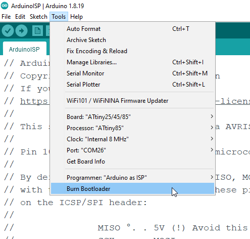
Next, select the communication port. Next, select the Programmer “Arduino as ISP”. Finally, click on the Burn Bootloader.
During the Bootloader burning, you will see flashing Leds on the Arduino Uno. The Bootloader burning process is going to take a few seconds. Once the Bootloader burning process is completed, the flashing Leds on the Arduino Uno will stop, and you will also see a message in the Arduino IDE. If it doesn’t make any sense to you, then you can watch my video tutorial given at the end of this article.
So, the Bootloader burning process is completed and now we are going to check if we can program the smallest Arduino “ATtiny85” using the Arduino IDE. So, let’s go ahead and control an LED.
Note: While burning the bootloader if it gives you an error, no need to panic, you can retry by clicking on the Burn Bootloader.
LED with ATtiny85:
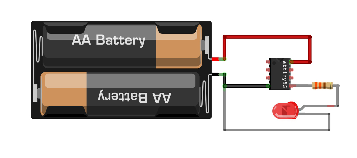
Connect your power source voltage and GND wires with the VCC and GND pins of the ATtiny85 microcontroller. The voltage should be from 2.7V to 5.5 volts. In the circuit diagram you can see two batteries. But you can use a 3.7V lipo battery or any other 5V regulated power supply.
Connect the Anode leg of the Led to pin 5(physical pin number) which is the digital pin 0. So, In the programming, we will refer to the physical pin 5 as pin 0. I am sure you got my point. Anyway, don’t forget to add a current limiting resistor of 330 ohms. And connect the Cathode leg of the LED with the GND.
Now, let’s go ahead and take a look at the LED blinking program.
LED Blinking ATtiny85 Arduino Code:
|
1 2 3 4 5 6 7 8 9 10 11 12 13 14 |
// the setup function runs once when you press reset or power the board void setup() { // initialize digital pin LED_BUILTIN as an output. pinMode(0, OUTPUT); } // the loop function runs over and over again forever void loop() { digitalWrite(0, HIGH); // turn the LED on (HIGH is the voltage level) delay(1000); // wait for a second digitalWrite(0, LOW); // turn the LED off by making the voltage LOW delay(1000); // wait for a second } |
This is the most basic LED blinking code. You can see, I have used the Digital pin 0 as the output to control an LED. And in the loop() function, you can see I am just turning ON and turn OFF the LED at a delay of 1 second. So, let’s go ahead and upload this program.
Right, now you can see the LED is not connected. And these are the same exact connections that I used for burning the Bootloader. So, we are going to use the Arduino Uno for uploading the program. So, to upload the program, I simply click on the Upload button. After uploading the code, next, I removed all the wires.

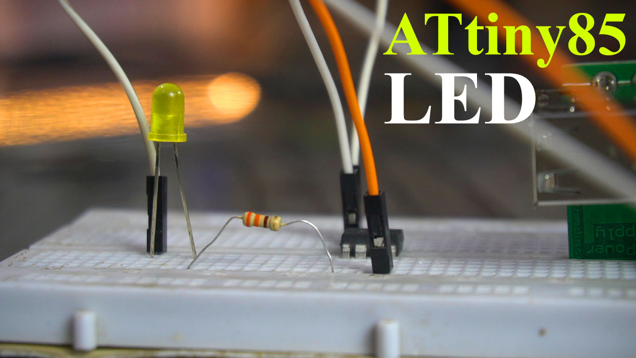
I connected my 2.5V LED with the ATtiny85 as per the circuit diagram. And I am going to use my designed 5V and 3A power supply. This power supply takes up to 28 volts input and on the output it gives regulated 5 volts. So, with this power supply we can power up the ATtiny85 controller using Solar panels, Batteries, and other DC adaptors. You can watch my video on how to make this amazing 5V and 3A power supply. So, let’s go ahead and power up the smallest Arduino based on the ATtiny85 microcontroller.

You can see the LED is blinking which means we have done everything correctly. In my upcoming videos, I will use the ATtiny85 controller in intermediate and advanced level projects. So, that’s all for now.
Watch Video Tutorial:
https://youtu.be/akUUHkYS-yE
Discover more from Electronic Clinic
Subscribe to get the latest posts sent to your email.
Thanks
I WANT TO UPLOAD AND RUN A PROGRAM FOR CONTROLLING
A RELAY USING IR REMOTE SENSOR USING ARDUINI NANO. I WROTE A SKETCH WHICH IS UPLOADED AND RUN SUCCESSFULLY ON BOTH NANO AND UNO. BUT, BUT WHEN I TRIED TO RUN THAT PROGRAM ON ATTINY85 IT REFUSES TO WORK. THE SKETCH WAS UPLOADED SUCCESSFULLY BUT DID NO RUN AT ALL. I HAVE SEARCHED FOR SUITABLE PROGRAMS, FOUND SOME, WORKED WITH THEM BUT WITHOUT RESULT. SEEKING HELP.