How to Make Arduino Pro Micro at Home, Altium Designer
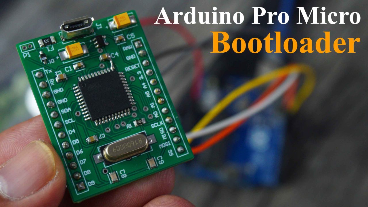
Arduino Pro Micro Bootloader
Last Updated on August 16, 2024 by Engr. Shahzada Fahad
Table of Contents
How to Make Arduino Pro Micro:
How to Make Arduino Pro Micro at Home, Altium Designer- In this article, we are going to make Arduino Pro Micro. My first article in this products designing series was based on the 5V and 3A power supply, which I successfully tested. And I have been using it to power up my Arduino projects, ESP32 based projects, Raspberry Pi Pico, ESP8266 and so on. Even I have been using it to charge my cell phone.
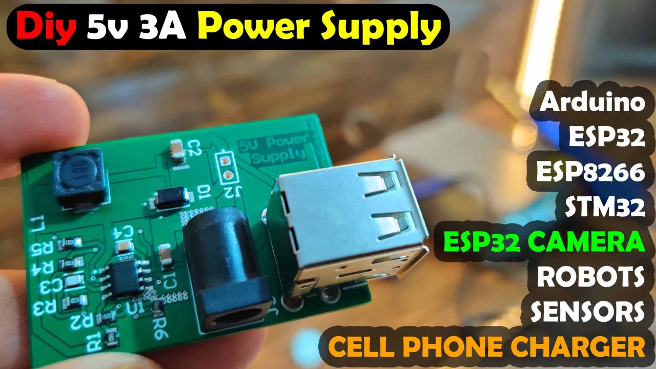
So, I am pretty satisfied with this 5V and 3A power supply.
Now, the 2nd article in this series is based on the Arduino Pro Micro. And I am going to share with you each and every detail; including
- Its circuit diagram, PCB Design, and how to generate Gerber files.
- How to place online order on a PCB Manufacturing website.
- From where to purchase all these SMD components?
- How to apply Solder Paste onto the PCB, how to place SMD components, and the soldering using SMD rework station.
- How to burn Bootloader on Arduino Pro Micro? And
- Testing
During the testing phase, first I will start by powering up the Arduino Pro Micro using the Laptop and then I will use my designed 5V and 3A power supply to power up the Arduino Pro Micro. And of course, I will write some basic code to control an LED to practically demonstrate that everything works perfectly. So, without any further delay; let’s get started!!!
Amazon Links:
*Disclosure: These are affiliate links. As an Amazon Associate I earn from qualifying purchases.
Arduino Pro Micro Circuit Diagram:
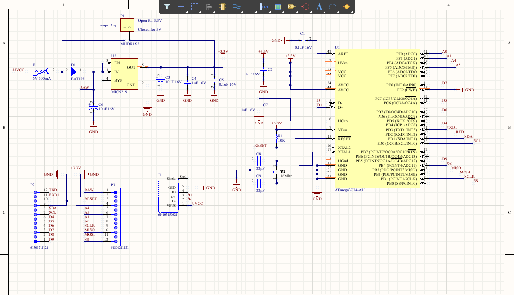
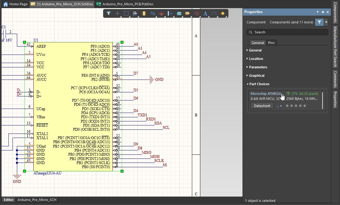
I have used Altium Designer for components researching, creating the schematic, and designing the PCB. Before creating a schematic, you should know which components you are going to use. After that, you should check if the components you are using are available in the market, what their prices are, and how to order them. So before making the final schematic, you need to spent some time on components researching, and you can do this perfectly in Altium Designer because it is connected with the world’s fastest components search engine, Octopart.
Select the component, click on the properties, and go to Part Choices. You will see the price and also the datasheet.
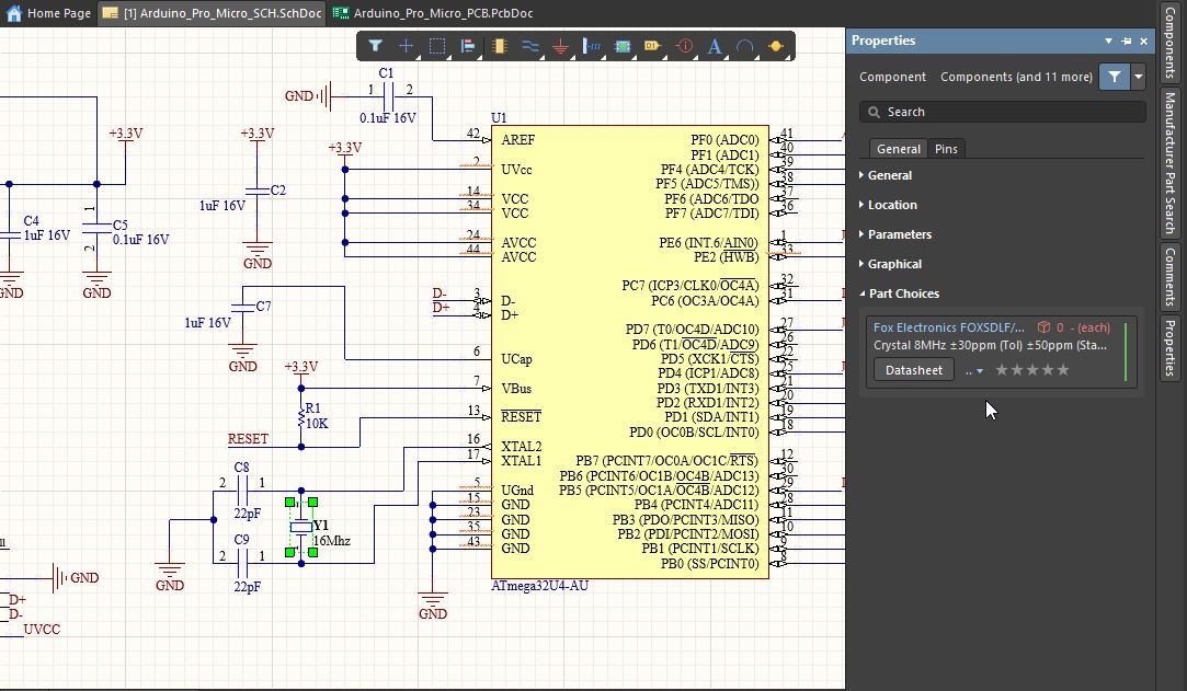
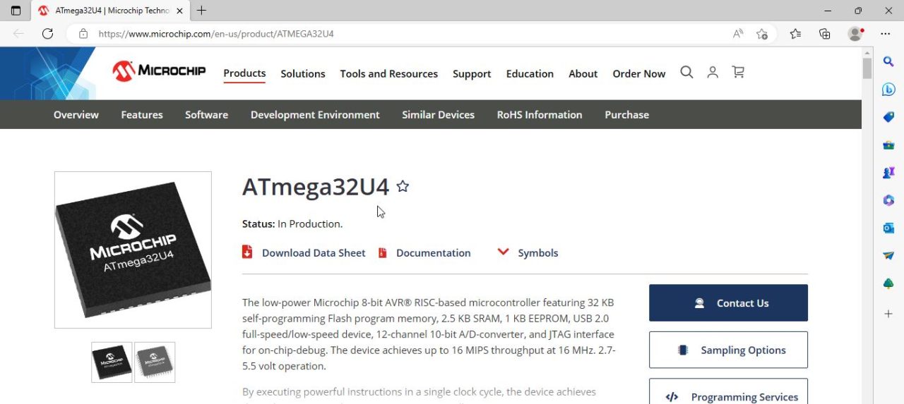
If you want to check the datasheet just go ahead and click on the datasheet, in my case I have already done my research work and this is the component I need. Now, to check the price and to order this component you can click on the price.
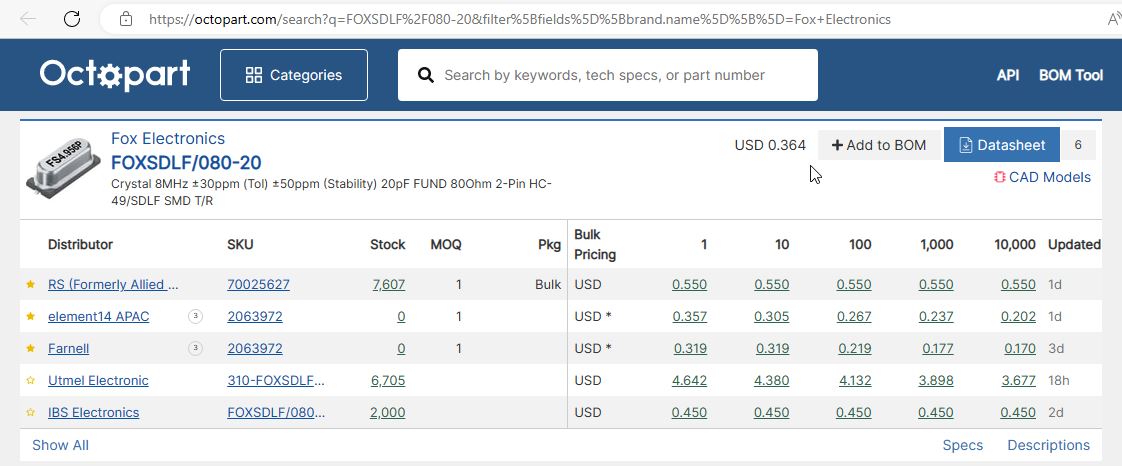
You can add this part to the BOM “Bill of Materials” you can also see the price. You can see distributors, the stock, Bulk Pricing, these values are frequently updated.
Now, let’s go back to Altium designer and this time let’s check ATmega32U4.
Just go ahead and click on the purchase options. So, this is how easily you can order all your components.
You can also do it the easiest way, as I did. In Altium Designer, go to Reports Menu and click on Bill of Materials.
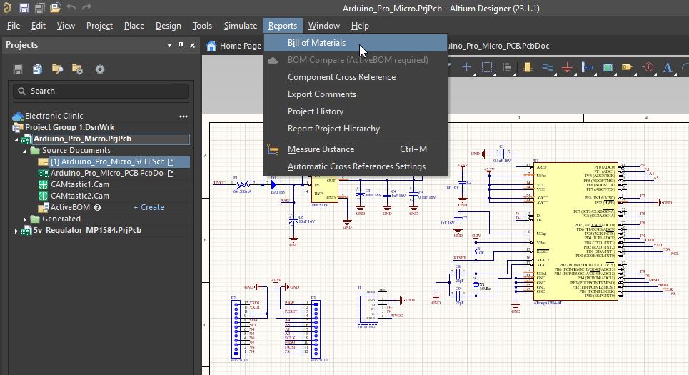
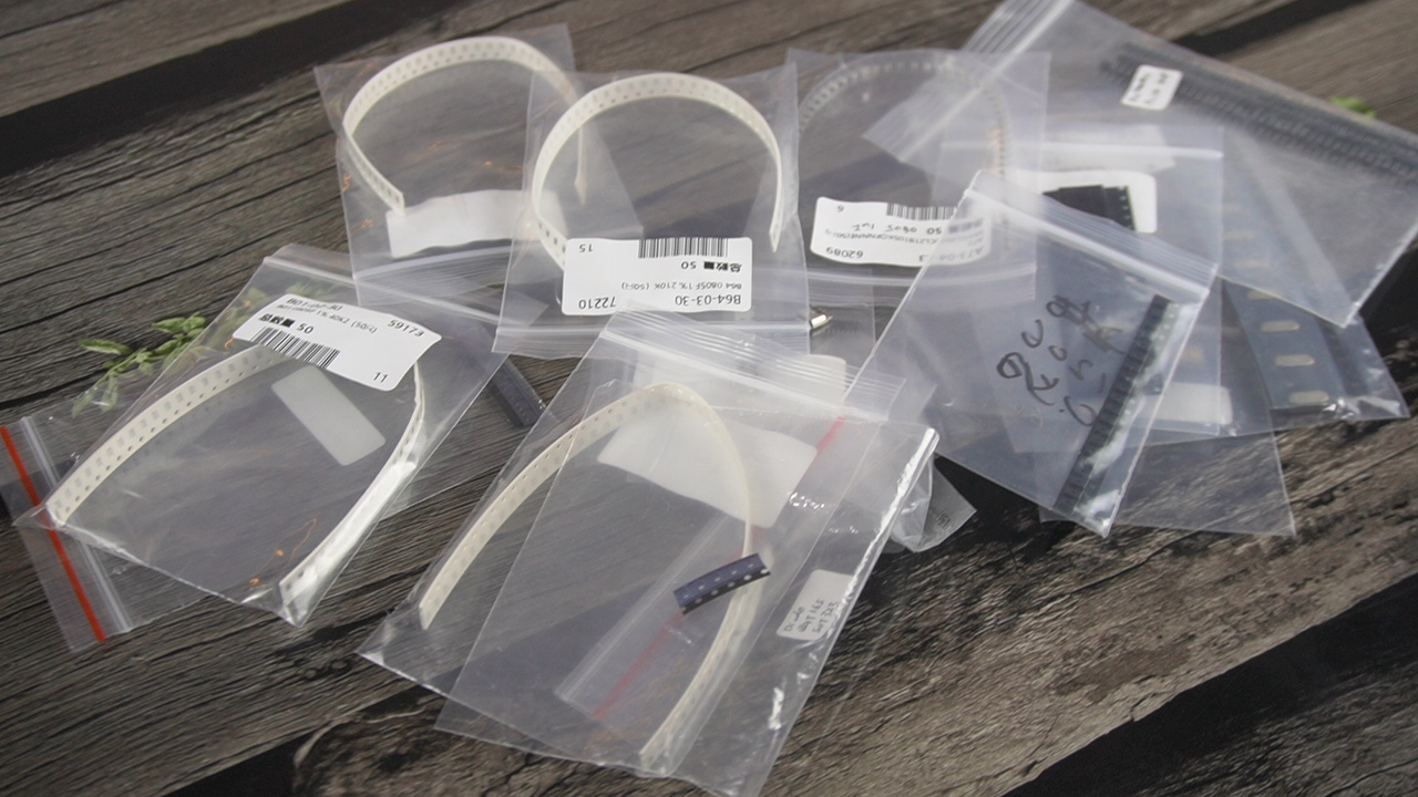
Altium designer will generate a complete BOM file for you. Click on the Preview button. Save this file and send it to a distributor and they will arrange all the components for you. In my case, I sent my BOM file to SunFounder. I am really thankful to SunFounder for sponsoring all the tiny SMD and through-hole components. I have been using their products and I am pretty satisfied. If you are looking for High Quality and low-cost Raspberry Pi and Arduino boards, Starter kits, Portable monitors, Robots, Sensor modules, and other tools then you should definitely visit SunFounder.
Now that you have all the components and they are available. Next, you can start the wiring which hardly takes a few minutes. I have already a very detailed video on how to make a schematic and PCB using Altium Designer. Anyway, then I switched over to the PCB designing document, I defined the PCB board size and re-arranged all the components.
Using Altium Designer you can automatically route all the wires.
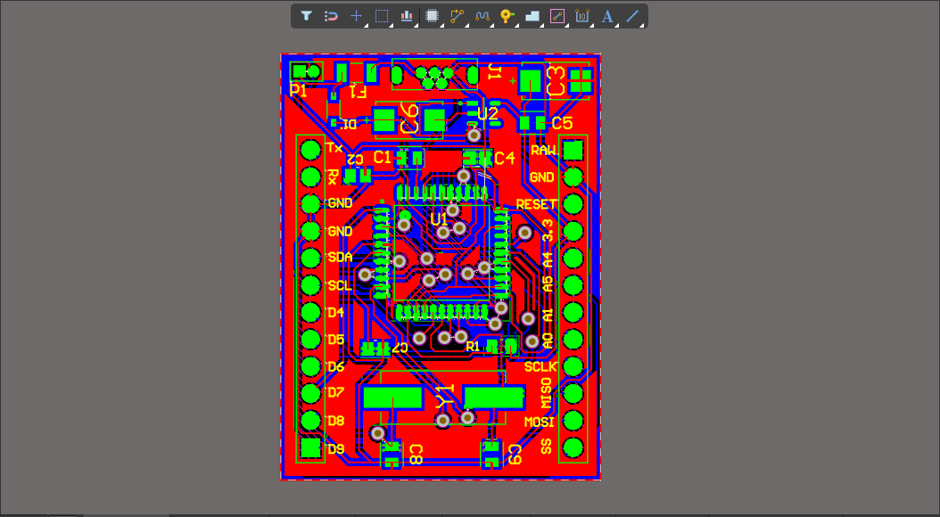
Finally, before generating the Gerber files, I activated the 3D layout mode by pressing number 3 on the keyboard.
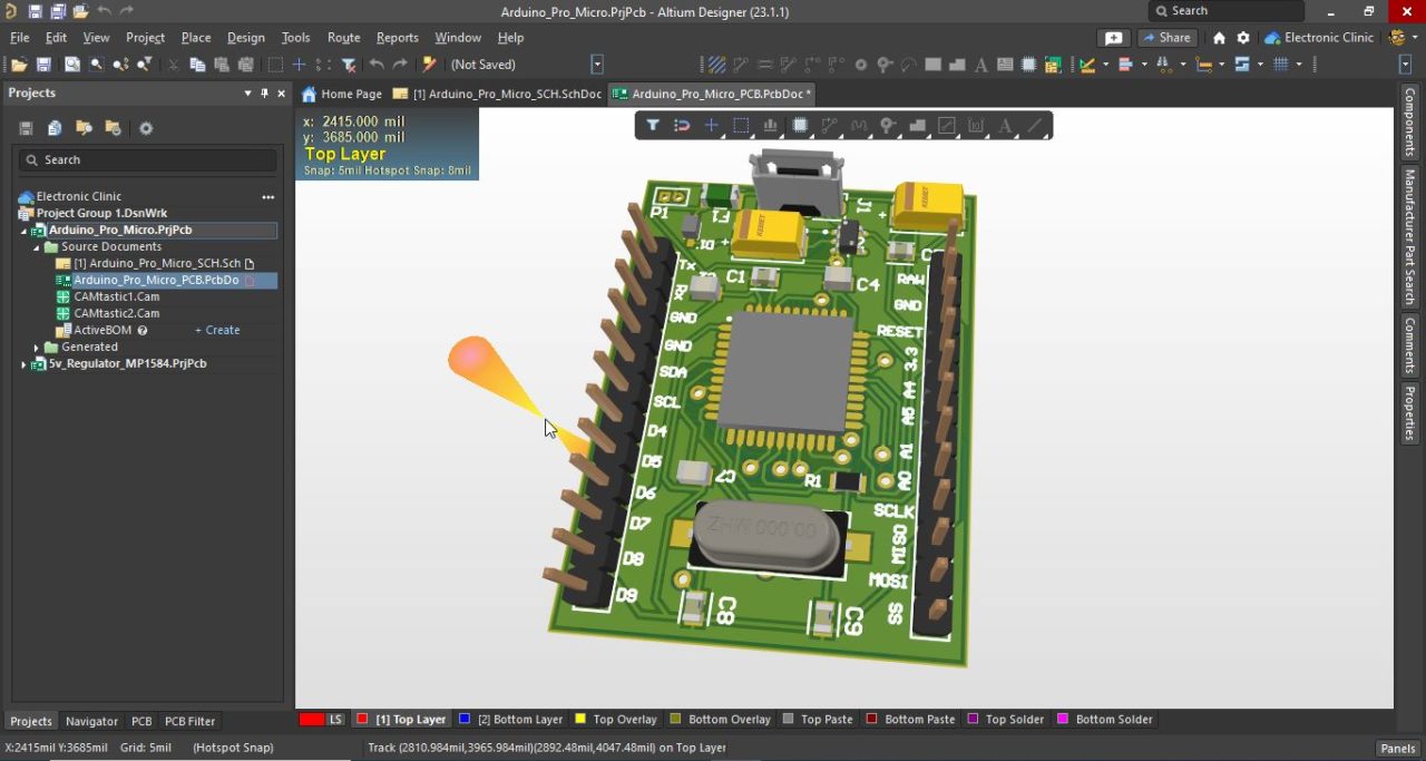
I double-checked all the connections and once satisfied. I again activated the 2D layout mode by pressing number 2 on the keyboard.
Finally, I was ready to generate the Gerber files.
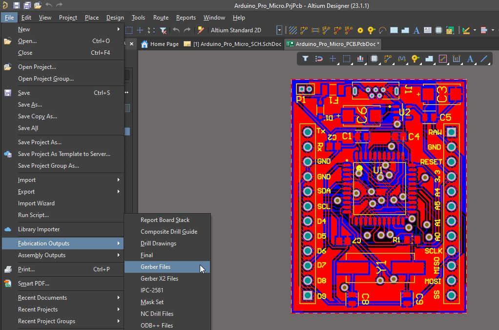
Go to the File Menu then to Fabrication Outputs and click on the Gerber Files.

On the Gerber setup, select inches in the units, and from the Plot Layers at the bottom, select Used. Finally, you can click on the apply button. This will generate the Gerber files for you.
Next, we will generate the NC Drill files.

Go to the File Menu then to Fabrication Outputs, and click on the NC Drill Files.
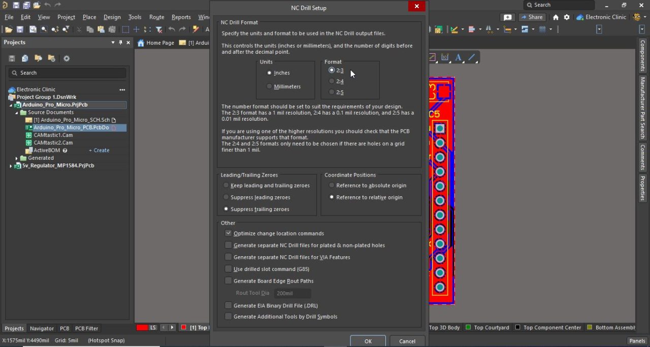
On the NC Drill Setup, select Inches on the Units tab, and select 2:3 on the Format tab. Finally, you can click on the OK button and this will generate the Drill files for you.
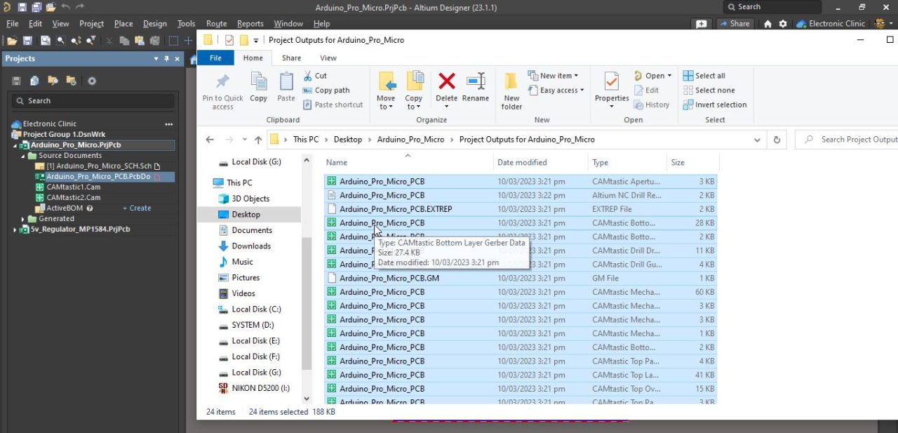
Now, I have the PCB Gerber files and the NC Drill Files. Right click on the project name and select explore this will open the project folder. Open the Project Outputs folder, now, these are the output files that we need to send to the PCB manufacturing company.
Now, to confirm that everything is done correctly, you can use the PCBWay online Gerber viewer.
Drag and drop all the files.
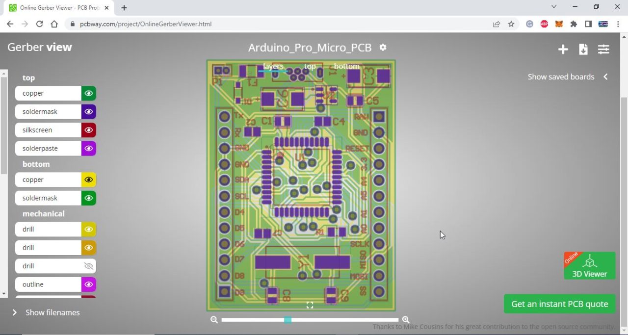
You can check all the individual layers and once satisfied then you can click on the Get an instant PCB Quote.
Steps to add Gerber files:
Click on the Add Gerber File button and select the folder.

It automatically detects the number of layers and board size. Next, you can select the number of PCBs you want to order. You can change the PCB color and all the other parameters as per your needs, in my case I am going to go with the default values and I am also going to select the SMD-Stencil. Finally, click on the Save to Cart button.
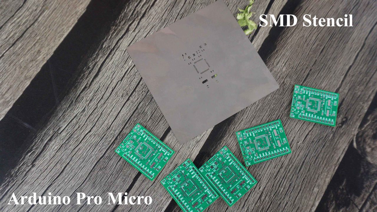
These are the PCBs I received from PCBway. As you can see the quality is really great. The silkscreen is quite clear and the Solder mask looks amazing and on the top is the SMD-Stencil.
Applying Solder Paste onto the PCB:
Now, that I have all the required components and tools so let’s go ahead and apply solder paste on this PCB.
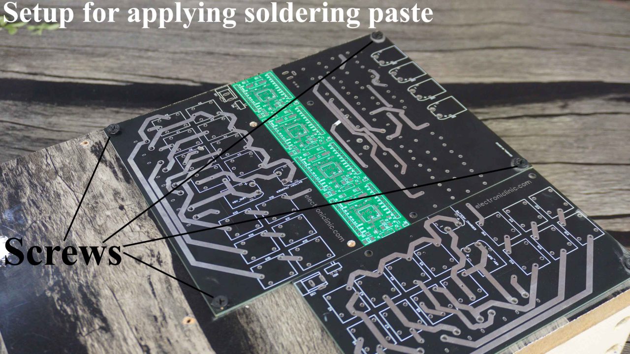
This is the most important step and you need to be very careful if you want clean and professional finishing. To be very frank this is my 2nd time doing the SMD soldering. Anyway, rather than using the electrical tape for securing the PCBs, I am using screws to tightly hold these PCBs in place, so that these PCBs doesn’t move when I apply the soldering paste.
Next, align your SMT Stencil with the PCB and secure it with tape so that it doesn’t move when you apply the Soldering paste.
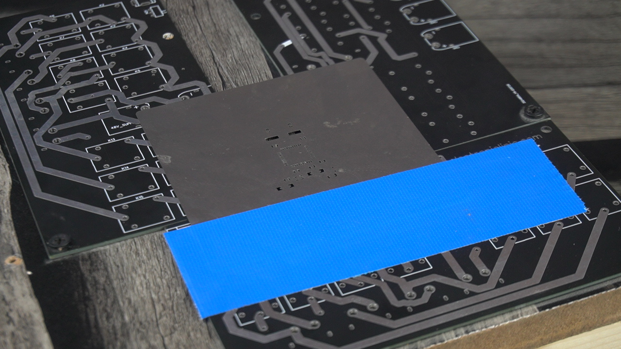
So, my setup is completed.
If you read my article on 5V and 3A power supply that’s when I did the SMD soldering for the first time and it really didn’t go well, because I made two mistakes.
- I was using a low-quality, cheap, and unbranded SMD Rework station. And
- My Soldering Paste was completely dried, and there was no temperature information printed on the container. And even if it was printed it wouldn’t have made any sense to me as this was my first time. So, my first SMD soldering badly failed at that time. And then I had to manually solder all the components.
This time round, what I did.
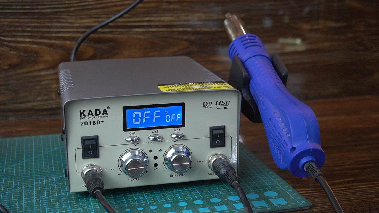
I purchased this good-quality entry-level SMD rework station. It has a display and it’s completely automatic.
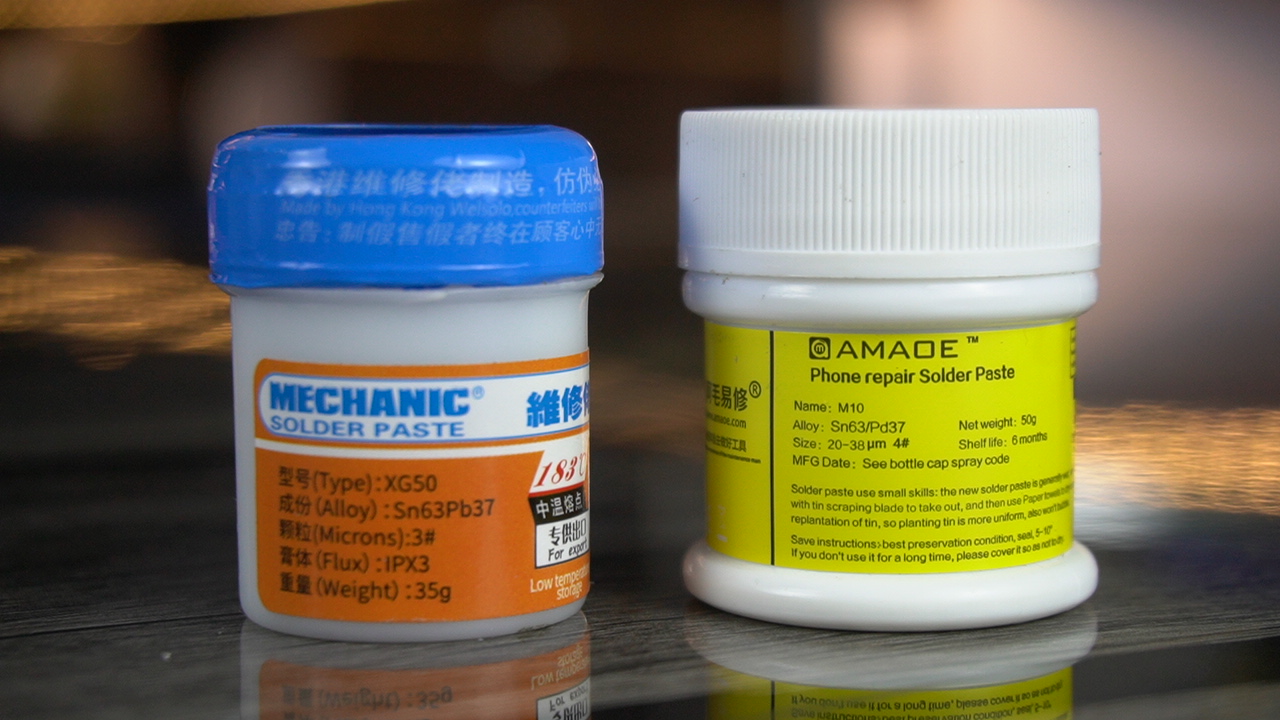
I also purchased two soldering pastes, both are 183 degrees Celsius. The Mechanic soldering paste is also good but the AMAOE is super awesome. So, I am going to use this soldering paste.
The soldering paste has been applied and it looks good.
Next, I placed the tiny SMD components on the PCB using non-magnetic ESD tweezers. And for this job I used my Andonstar Digital Microscope.

A digital microscope like the Andonstar is one of the must-have tools. Without a microscope, putting these tiny SMD components on the PCB would have been so difficult.
You can see all the SMD components have been placed and now we will start the soldering.
On my SMD rework Station, I am going to set the Air Flow speed to 1 as I don’t want my SMD components to fly away. And I am going to set the temperature between 300 and 350 degrees Celsius. For the practical demonstration watch video tutorial given at the end of this article.
The soldering is completed and it doesn’t look bad. Anyway, I used my digital multimeter to check for any short circuits and I also checked the continuity. I double-checked all the connections using my Andonstar Digital Microscope. Finally, I cleaned my circuit
With a PCB cleaning liquid.
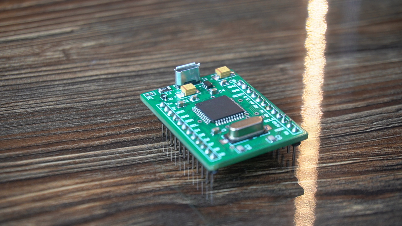
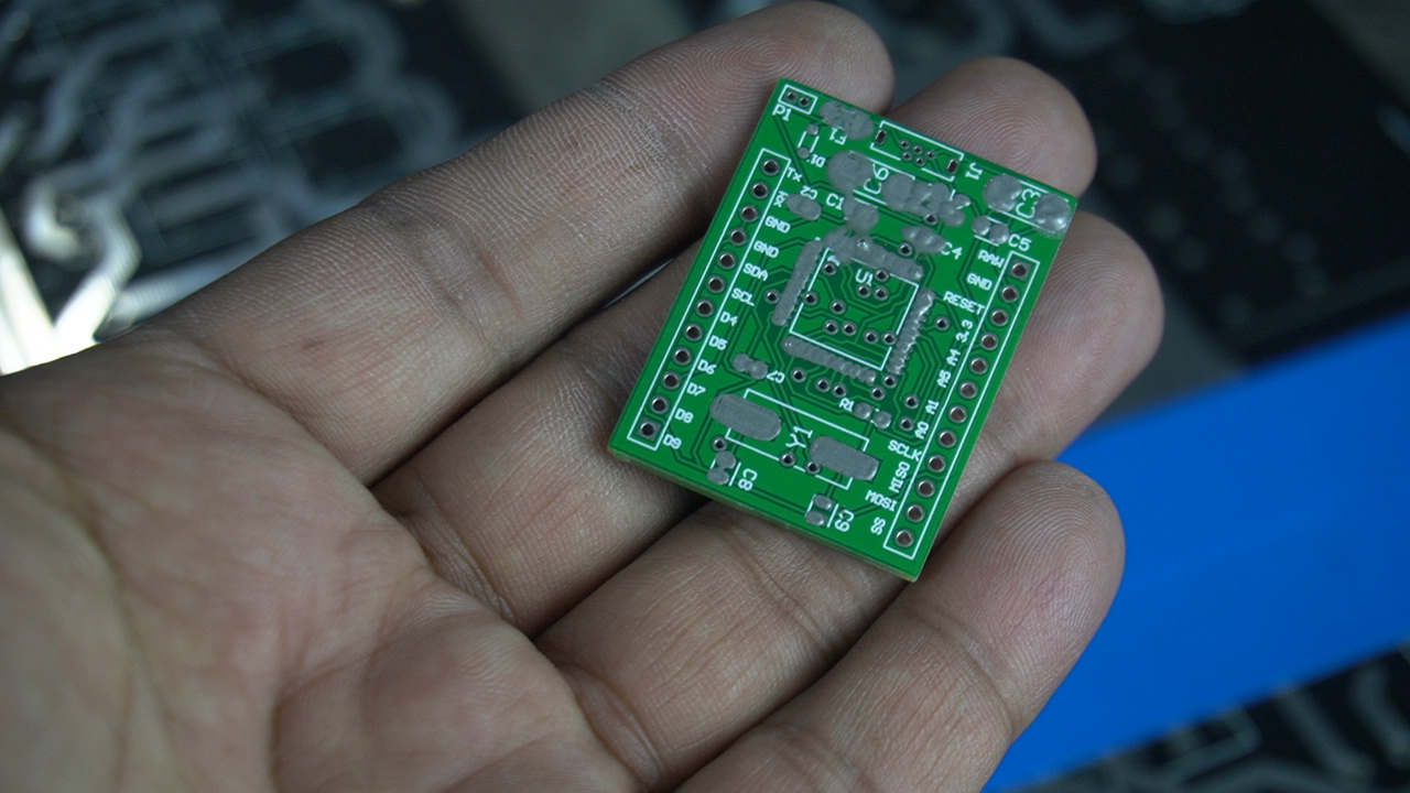
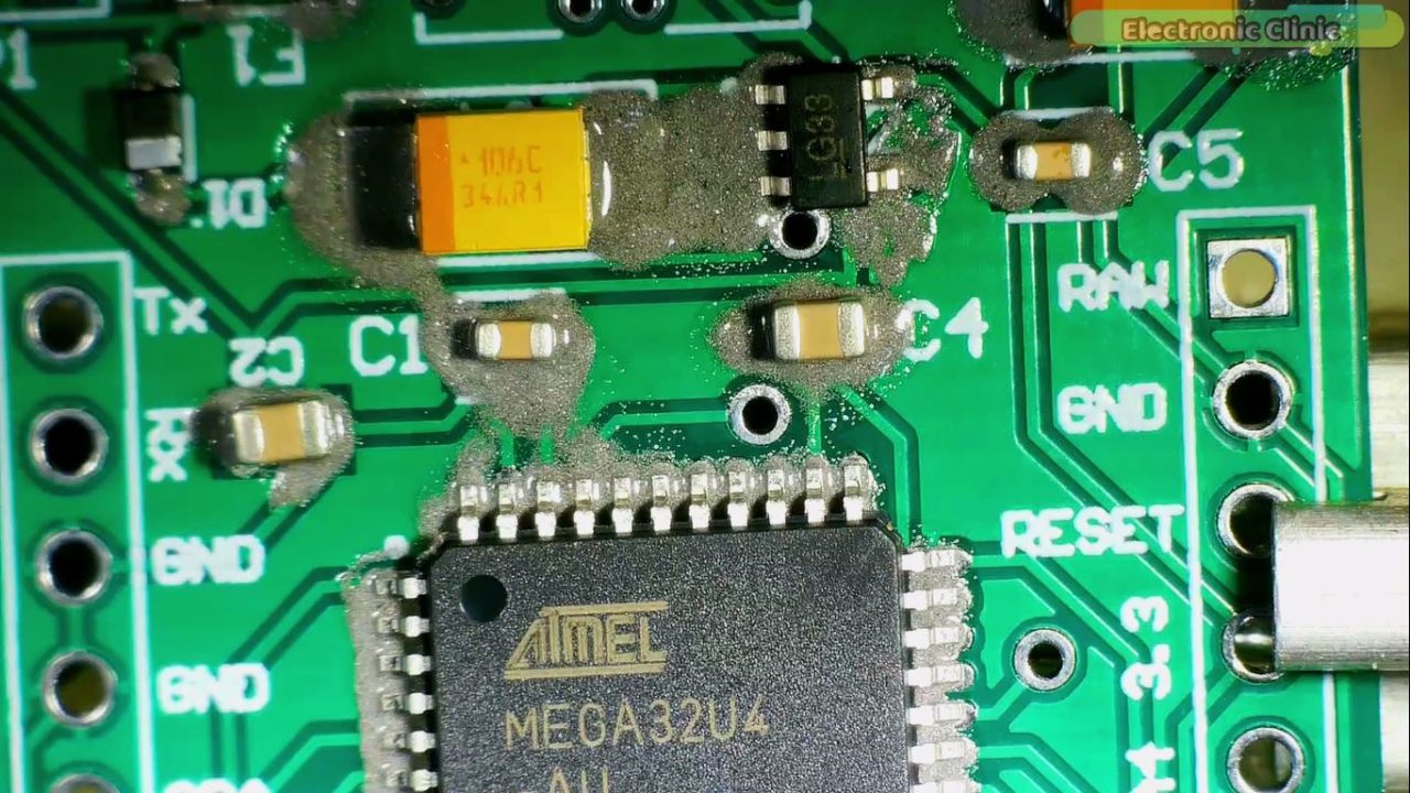
I also soldered the male headers and the micro USB port. So, this is the final look of my Arduino Pro Micro. Now, the next step is to burn the Bootloader on the Arduino Pro Micro.
But, I am going to check the continuity and short circuit test one more time, because I didn’t check the power supply and GND pins.
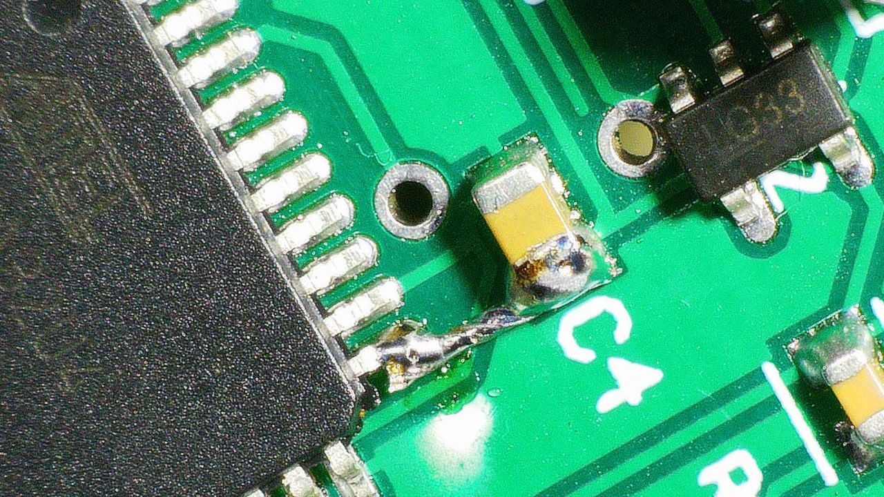
While testing all the connections, I found the 3.3V pin was not connected with any of the 3.3V pins of the controller. At this point, I was pretty shocked. Anyway, to confirm the wiring I run the DRC or Design Rule Check. And in just a few seconds Altium found an un-routed Net. I was supposed to run the DRC check before generating the Gerber files. Anyway, I will fix this issue, but for now,

I am going to solder these two points, because without it, I won’t be able to supply 3.3V to the controller. So, let’s do it.
Now, my Arduino Pro Micro is ready, and now let’s move on to the next step which is burning the Bootloader.
Burn Bootloader on the Arduino Pro Micro:
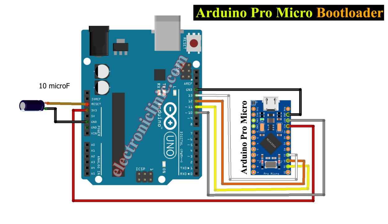
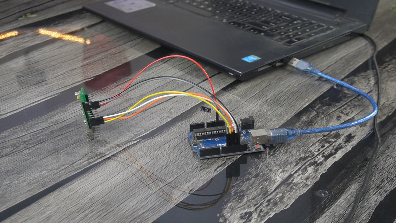
Connect the MOSI, MISO, and SCLK pin of the Arduino Pro Micro with the MOSI, MISI, and SCLK pins on the Arduino Uno. Connect VCC or 3.3V pin of the Arduino Pro Micro with the 3.3V pin of the Arduino. Connect the Reset Pin of the Arduino Pro Micro with pin 10 on the Arduino. And make sure you connect the ground pins of both the boards together. Connect a 10uF capacitor between the Reset and GND pins of the Arduino Uno. Make sure you connect the positive leg of the Capacitor with the Reset and GND leg with the Ground.
You can see I have connected my Arduino Pro Micro with the Arduino as per the circuit diagram. On my board, I have clearly labeled the MOSI, MISO, SCLK pins.

You can see a 10uf capacitor connected between the Reset and GND pins, make sure you connect the positive leg of the capacitor with the Reset pin.
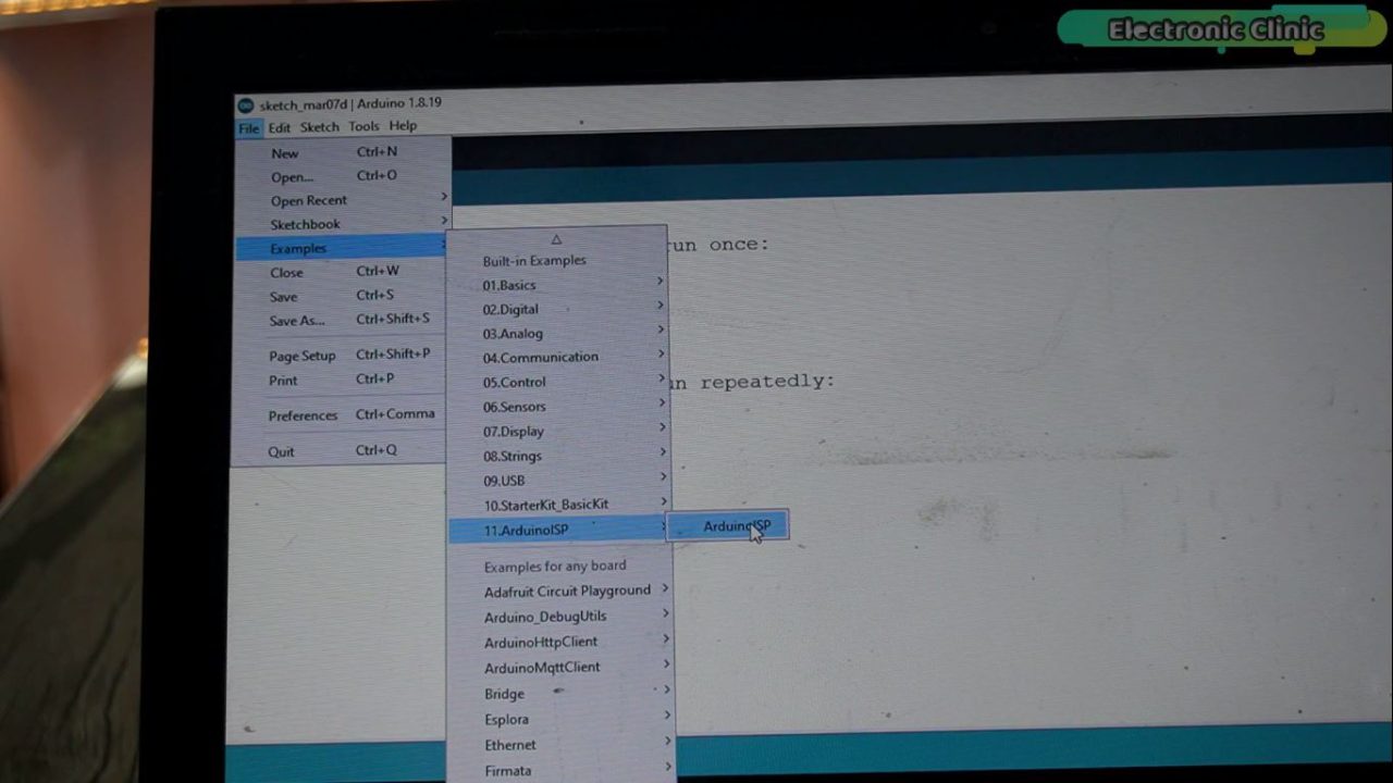
My entire setup is ready and now I am going to connect my Arduino Uno to the Laptop. To be on the safe side, make sure you have a latest version of the Arduino IDE installed. Next, on the Arduino IDE, go to the File Menu, then to Examples, and open ArduinoISP.
Next, go to the Tools menu, then to Board, and select Arduino Leonardo.
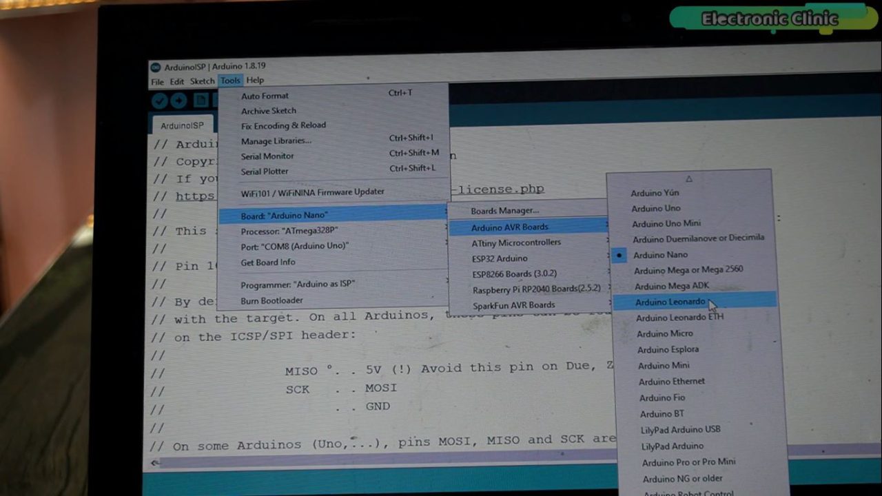
Again go to the Tools menu and this time select the communication port. Next, go to the Programmer and select Arduino as ISP.
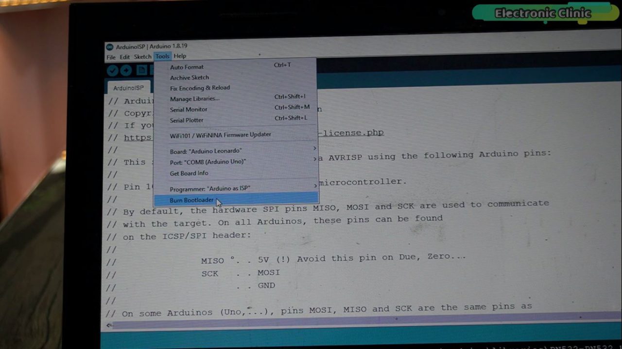
Finally, click on the Burn Bootloader. It doesn’t matter if you get an error, sometimes it happens, you can try again.
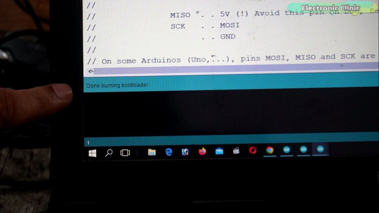
On the Arduino Uno you will see these Flashing LEDs, its going to take around 1 minute. The bootloader burning process is completed and you should also see this notification or message in the Arduino IDE as well.
Now, I can disconnect my Arduino board, and I can remove all the wires. Because, now I can use my Micro USB cable for uploading the code. Close the Arduino IDE and open it again. Connect your Arduino Pro Micro with the Laptop to check if the Arduino IDE can recognize this board. While the Arduino IDE is open, I can go to the Tools Menu and then to port and you can see it has successfully detected my Arduino board and its connected on communication port 25.

Now, let’s control an LED.
LED with Arduino Pro Micro:
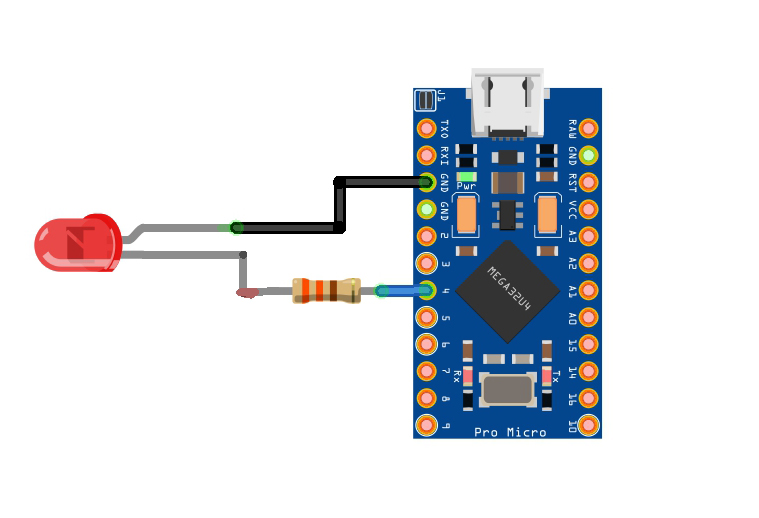
Connect the positive or Anode leg of the LED with the digital pin D4 through a 330 ohm resistor and connect the cathode leg of the LED with the GND pin of the Arduino Pro Micro.

You can see I have connected this 2.5V LED with the Arduino Pro Micro as per the circuit diagram. And now let’s take a look at the programming.
Arduino Pro Micro Led Blinking Code:
|
1 2 3 4 5 6 7 8 9 10 11 12 13 14 |
// the setup function runs once when you press reset or power the board int led=4; void setup() { // initialize digital pin LED_BUILTIN as an output. pinMode(led, OUTPUT); } // the loop function runs over and over again forever void loop() { digitalWrite(led, HIGH); // turn the LED on (HIGH is the voltage level) delay(1000); // wait for a second digitalWrite(led, LOW); // turn the LED off by making the voltage LOW delay(1000); // wait for a second } |
I have this basic program and you can see I have defined a pin for the LED and I am using digital pin D4 on the Arduino Pro Micro. In the loop() function I am just turning ON and turning OFF this led at a delay of 1 second. So, let’s go ahead and upload this program.
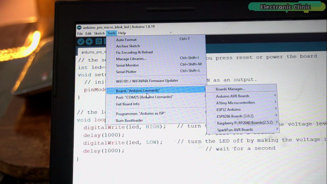
Go to the Tools Menu and select the board “Arduino Leonardo”. Then select the communication in my case COM25. Select the Programmer as “Arduino as ISP”. Finally, you can click on the upload button.

The Led is blinking and this means my Arduino Pro Micro is working. In my upcoming videos, I will use it in some intermediate and advanced-level projects. So, that’s all for now.
Watch Video Tutorial:
https://youtu.be/UU-Tbn8yXEk
Discover more from Electronic Clinic
Subscribe to get the latest posts sent to your email.


