Seeeduino XIAO Pinout, specifications, & Programming using Arduino IDE
Table of Contents
Description:
Seeeduino XIAO Pinout, specifications, & Programming using Arduino IDE– In this tutorial, you will learn about the smallest Arduino Seeeduino XIAO. In this tutorial, I will cover the extreme basics before I am going to use this smallest Arduino Seeeduino XIAO in some beginner’s level, intermediate level, and advanced level projects.
In this tutorial, we will cover,
- Seeeduino XIAO Technical Specifications
- Seeeduino XIAO Pinout
- Seeeduino XIAO Board Manager installation
- Seeeduino XIAO Programming using Arduino IDE
Without any further delay let’s get started!!!
Amazon Purchase Link.
Arduino Nano USB-C Type (Recommended)
Other Tools and Components:
ESP32 WiFi + Bluetooth Module (Recommended)
Super Starter kit for Beginners
PCB small portable drill machines
*Please Note: These are affiliate links. I may make a commission if you buy the components through these links. I would appreciate your support in this way!
Seeeduino XIAO:
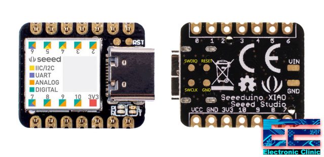
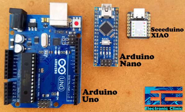
This is the smallest Arduino Seeeduino XIAO. It is an Arduino microcontroller that is embedded with the SAMD21 mirochip. The first most prominent thing that you will notice about the Seeeduino is its very small size when compared with the Arduino Uno and Arduino Nano and is claimed to be the smallest member of the Seeeduino family.
Seeeduino XIAO carries the powerful CPU-ARM Cortex M0+ (SAMD21G18) which is a low-power Arduino Microcontroller. The Seeeduino is ideal for wearable devices and small DIY projects.
Seeeduino XIAO SPECIFICATIONS:
CPU ARM Cortex-M0+ CPU(SAMD21G18) running at up to 48MHz
Flash Memory 256KB
SRAM 32KB
Digital I/O Pins 11
Analog I/O Pins 11
I2C interface 1
SPI interface 1
UART interface 1
Power supply and downloading interface Type-C
Power 3.3V/5V DC
Dimensions 20×17.5×3.5mm
Typical Application
Wearable devices
Rapid prototyping (directly attached to the expanded PCB as a minimal system)
Perfect for all the projects need mini Arduino
DIY keyboard
USB development (USB to multi-channel TTL/USB host mode, etc.)
A scenario where you need to read multiple mock values The DAC output
Key Features
Powerful CPU: ARM® Cortex®-M0+ 32bit 48MHz microcontroller(SAMD21G18) with 256KB Flash,32KB SRAM
Flexible compatibility: Compatible with Arduino IDE
Easy project operation: Breadboard-friendly
Small size: As small as a thumb(20×17.5mm) for wearable devices and small projects.
Multiple development interfaces: 11 digital/analog pins, 10 PWM Pins, 1 DAC output, 1 SWD Bonding pad interface, 1 I2C interface, 1 UART interface, 1 SPI interface.
Seeeduino XIAO Pinout:
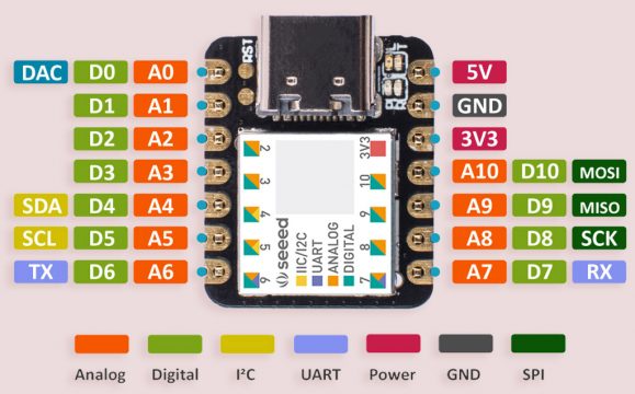
The Seeeduino has a total of 14 GPIO PINs, which can be used for 11 analog PINs, 11 digital PINs, 1 I2C interface, 1 UART interface, and 1 SPI interface. Some PINs have various functions, A1/D1 to A10/D10 Pins have PWM functions and Pin A0/D0 has a function of DAC which means you can get true analog signals not PWM signals when you define it as an analog pin, that’s why 14 GPIO PINs can realize more I/O PINs and interfaces.
Interrupt:
All pins on Seeeduino XIAO support interrupts, but two pins cannot be used at the same time: Pin 5 and Pin 7.
Moreover, Seeeduino XIAO supports the USB Type-C interface which can supply power and download code.
Seeeduino XIAO Battery:
There are power pads at the back of the XIAO which support battery and make it designed for wearable devices to become realistic. Except for the power LED, we add a user LED on board for your better coding experience. Usually a Dev. Board as small as this size will use the chip’s inner crystal oscillator for time fixing, in order to make the clock more accurate, Seeeduino XIAO layouts an extra 32.768KHz to make the clock more stable.
Reset
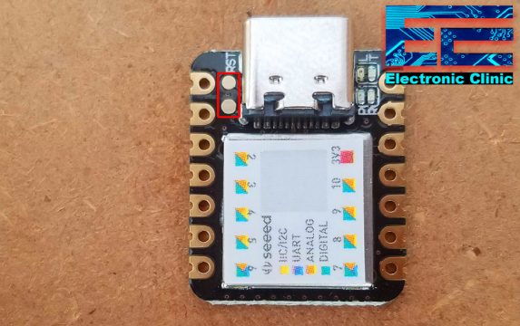
Sometimes the Seeeduino XIAO port may disappear when the user programming process fails. You can solve this problem by the following operation:
Connect the Seeeduino to your computer and short these two points twice.
At this point, the chip enters Bootloader mode and the burn port appears again. Because the samd21 chip has two partitions, one is the Bootloader and the other is the user program. The product will burn a bootloader code in the system memory when it leaves the factory. We can switch modes with a quick reset.
Attention:
You need to be careful while using the Seeeduino as All the I/O pins are 3.3V do not input more than 3.3V; otherwise, the CPU may be damaged. For the 5V sensors and breakout boards, you can use a voltage level converter.
Seeeduino XIAO Soldering Male Headers:
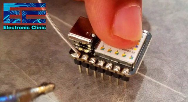
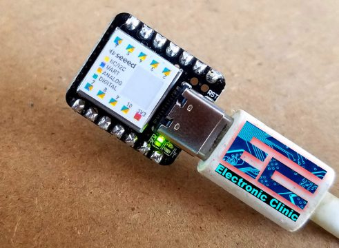
I soldered the male headers, so that I can easily use the Seeeduino XIAO with the Breadboard.
Seeeduino XIAO Arduino IDE:
Seeeduino XIAO is perfectly compatible with the Arduino IDE. To program the Seeeduino XIAO using the Arduino IDE you will need to install the Seeeduino XIAO Board.
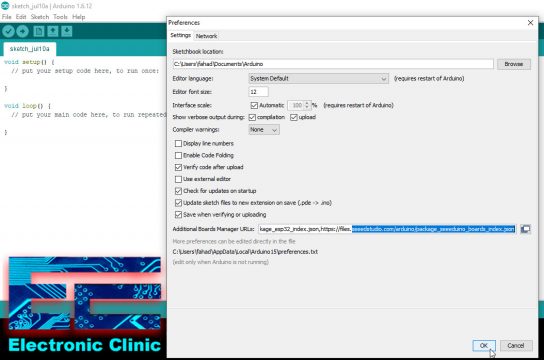
While the Arduino IDE is open. Copy the URL link given below.
Seeeduino XIAO Board Manager URL Link:
https://files.seeedstudio.com/arduino/package_seeeduino_boards_index.json
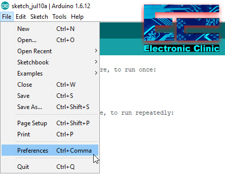
Click on the File Menu and then click on the preferences.
You can directly paste this URL, or if you have already added some URLs, then all you need is simply put a comma and then paste the URL. Finally, click on the Ok button.
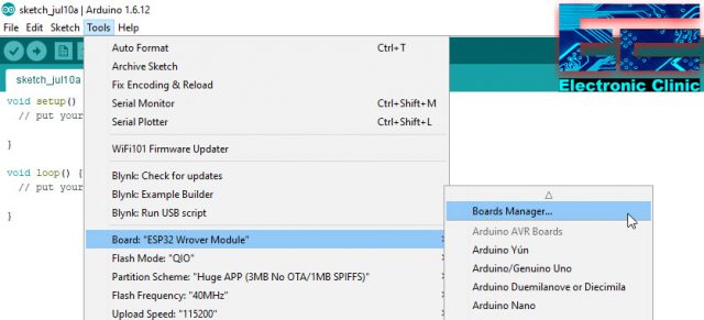
Click on the Tools menu, go to boards, and then click on the boards manager.
Search for the Seeeduino and install the latest version
This may take several minutes depending on the speed of your internet connection. As you can see in the picture above, I have already installed the Seeeduino XIAO board. The board installation took around 37 minutes due to the slow internet connection. After, you have installed the Seeeduino XIAO board, the next and final step is to confirm if the Seeeduino XIAO board is available in the Arduino Boards list.
Again click on the Tools menu go to boards and check if the Seeeduino XIAO board is added.
As you can see the XIAO board is available. Now we are all set. On the left side, you can see the Port is disabled as the Seeeduino is still not connected with the Laptop. As we are done with the Board installation and now we can start the programming, so let’s go ahead and connect the Seeeduino board with the Laptop.
When you connect the XIAO with the Laptop, two LEDs are turned ON, the green led remains ON while the yellow LED turns ON and turns OFF at around 1 second interval.
As you can see the port is enabled and on the right side you can see Seeeduino XIAO is available on COM7. Now the XIAO is ready for the programming. It’s programming is just like the Arduino Uno. The only difference is it has got more Analog pins and is very small in size. Just for your understanding, I am going to share with you some very basic programs that you can use to check your Seeeduino board.
Seeeduino XIAO Example Codes:
Seeeduino XIAO Hello World Example:
|
1 2 3 4 5 6 7 8 9 10 |
void setup() { // put your setup code here, to run once: Serial.begin(9600); } void loop() { // put your main code here, to run repeatedly: Serial.println("Hello world! Seeeduino XIAO"); delay(1000); } |
The purpose of the above code is to send the “Hello world! Seeeduino XIAO” message to the serial monitor. This is the most basic program which can be used to check if the Seeeduino is working.
Seeeduino XIAO LED Blinking:
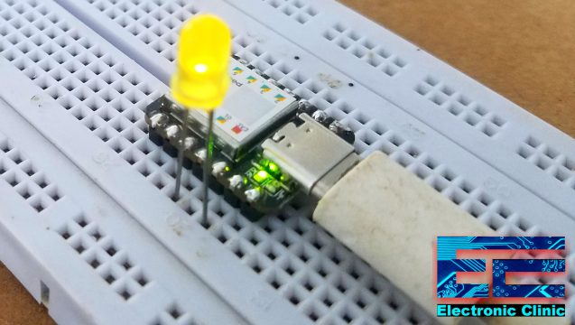
The anode leg of the LED is connected with the Seeeduino pin number 10 and the cathode leg is connected with the ground pin.
Seeeduino XIAO LED Blinking Program:
|
1 2 3 4 5 6 7 8 9 10 11 12 13 14 |
int LED = 10; void setup() { // put your setup code here, to run once: pinMode(LED, OUTPUT); } void loop() { // put your main code here, to run repeatedly: digitalWrite(LED, HIGH); delay(1000); digitalWrite(LED, LOW); delay(1000); } |
This is a very basic LED blinking program. The purpose of this code to turn ON and turn OFF the LED. I am using a 1 second delay.
Seeeduino XIAO Analog Sensor:
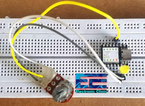
This time I added a Potentiometer with the Analog Pin A2 of the XIAO. The middle leg of the Potentiometer or variable resistor is connected with the XIAO PIN2. The other two wires of the Potentiometer are connected with the 3.3V PIN and Ground. While the LED connection remains the same. In this example, the potentiometer is used as the sensor, which is used to control the delay time. You can use any type of analog Sensor. For the 5V sensors don’t forget to add the Voltage level converter.
Seeeduino XIAO Analog Sensor Programming:
|
1 2 3 4 5 6 7 8 9 10 11 12 13 14 15 16 17 18 |
int LED = 10; int Pot = 2; // Potentiometer int Pot_Data = 0; void setup() { // put your setup code here, to run once: pinMode(LED, OUTPUT); pinMode(Pot, INPUT); } void loop() { // put your main code here, to run repeatedly: Pot_Data = analogRead(Pot); Pot_Data = map(Pot_Data, 0, 1023, 200,3000); digitalWrite(LED, HIGH); delay(Pot_Data); digitalWrite(LED, LOW); delay(Pot_Data); } |
The purpose of this program is to control the ON and OFF time delay of the LED using the Potentiometer. The potentiometer is read using the analogRead() function and the value is stored in the variable Pot_Data. The value is then mapped and is used as the delay.
From these examples you know, the Seeeduino XIAO is just like the Arduino. Very soon I will use the Seeeduino in some intermediate and advanced level projects.
Watch Video Tutorial:






Would be a great high speed Ardunio family part with NANO pinout. How long until that happens?
Hi Fahad, I did write to you earlier som etime ago, but I want to ask if there is any possibility that I/we can get permission to use your email??
We, two old boys (68 and 76 yrs), want to develop a small circuit, but we are realising we do not have all of the required skills. Therefore we want to ask if we can pay (as little as possible ?) to get some assistance from you??
If you do not think you have time for this, then maybe youknow somebody who can be interested in helping us out??
Please be kind and le tme hear from you at your earliest convenience?
Thank you in advance
*Flemming and PEER
I didn’t understand, what you mean by, you want to use my email?
I will help you with your projects, and there is no need to pay me. I will do it for free.
What project you are working on?
Could you please throw some light on the use of interrupts with this device, I am having a bit of trouble with them, experienced with Uno, Mega, micro and Mini Pro, as well as ATTiny 85 with interrupt usage. Any tips or help would be appreciated. I have no URL active at the moment, but had to add something as it is mandatory.
Sorted my interrupt issue, I was using an array to sequentially initialise four interrupts, but my range included both pins 5 and 7, which it appears are mutually exclusive as interrupts!