ATtiny85 and DHT21 Temperature & Humidity Sensor and SSD1306 Oled Display, Arduino
Last Updated on September 21, 2024 by Engr. Shahzada Fahad
Table of Contents
ATtiny85 and DHT21:
ATtiny85 and DHT21 Temperature & Humidity Sensor and SSD1306 Oled Display, Arduino- If you are just getting started with the ATtiny85 microcontroller then I highly recommend you should read my previous article on the ATtiny85 microcontroller because if you want to program this tiny microcontroller using the Arduino IDE then, first of all, you will need to burn a bootloader on the ATtiny85 microcontroller and besides this, you must also know about its technical specifications, how to add the ATtiny85 microcontroller in the Arduino IDE, and how to externally power up this microcontroller.
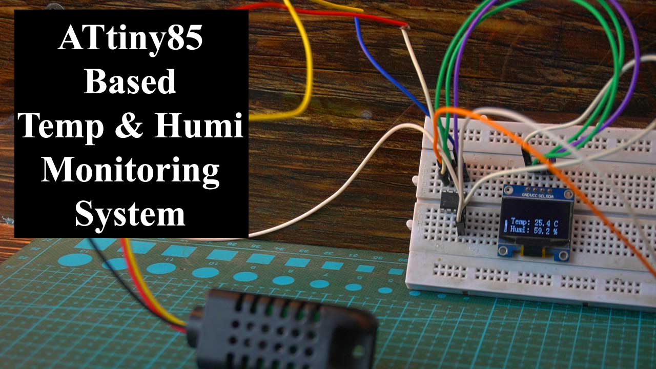
Anyway, in today’s article, we are going to make a Temperature and Humidity monitoring system using the most popular DHT21 Temperature and Humidity sensor, and the I2C-supported SSD1306 Oled display module.

Instead of using the DHT21 Sensor, you can also use the DHT11 Temperature and Humidity Sensor. If you haven’t purchased a temperature and humidity sensor yet, then I would recommend that you buy the DHT21 sensor. Because it’s fast and accurate compared to the DHT11 sensor. I have used these sensors in several beginner, intermediate, and advanced level projects.
Normally, I use the same Adafruit_GFX.h and Adafruit_SSD1306.h libraries when I use the SSD1306 Oled display module with the Arduino Uno, Arduino Nano, ESP32, and ESP8266 etc. But in the case of ATtiny85 these libraries didn’t work. So, later in this article, I will explain; which libraries to download and how to use them. So, without any further delay let’s get started!!!
Amazon Links:
Arduino Nano USB C type (Recommended)
DHT21 Temperature and Humidity Sensor
*Disclosure: These are affiliate links. As an Amazon Associate I earn from qualifying purchases.
ATtiny85 and DHT21 Circuit Diagram:

Connect the VCC and GND pins of the DHT21 Temperature and Humidity sensor to the 5V and GND pins on the ATtiny85 microcontroller. Pin4 on the ATtiny85 is the Ground while Pin8 is the VCC. Connect the Data wire of the DHT21 sensor to Pin6 which is the digital pin D1 as per the ATtiny85 Pinout diagram.
Similarly, connect the VCC and GND pins of the I2C supported SSD1306 Oled display module to the 5V and GND pins on the ATtiny85 microcontroller. Connect the SCL and SDA pins of the Oled display module to the pins 7 and 5 on the ATtiny85 microcontroller.
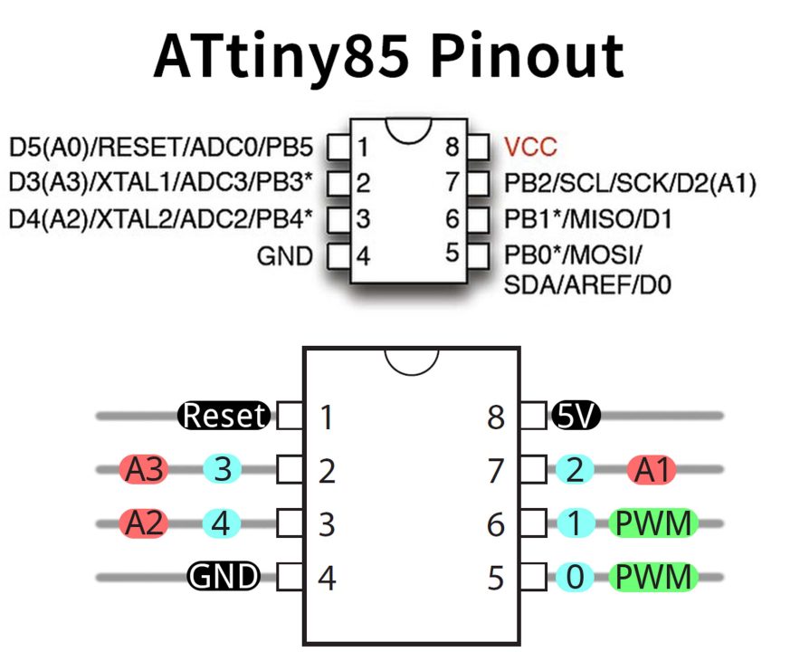
Pin7 is the SCL and Pin5 is the SDA as you can see in the ATtiny85 Pinout Diagram. You can use AAA batteries to power up your project, or you can use any 5V regulated power supply.

In my case, I am using my designed 5V and 3A power supply. As you can see I have connected the 5v and GND wires to the VCC and GND pins on the ATtiny85 microcontroller. I have a very detailed article on how to design a 5V and 3A power supply in Altium designer. So, that’s all about the connections. Now, let’s go ahead and install the required libraries.
ATtiny85 Arduino Libraries for SSD1306:
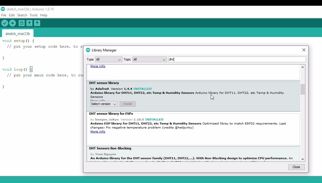
Make sure you have the latest version of the Arduino IDE installed on your computer or laptop. Anyway, we are going to install three libraries, one for the DHT21, and the other two libraries for the SSD1306 Oled display module. For this, go to the Sketch Menu, then to Include Library, and click on the Manage libraries.

search for the dht. As you can see I have already installed this library. And this is the same library I have been using with Arduino Uno and Arduino Nano. And it’s also compatible with the ATtiny85.
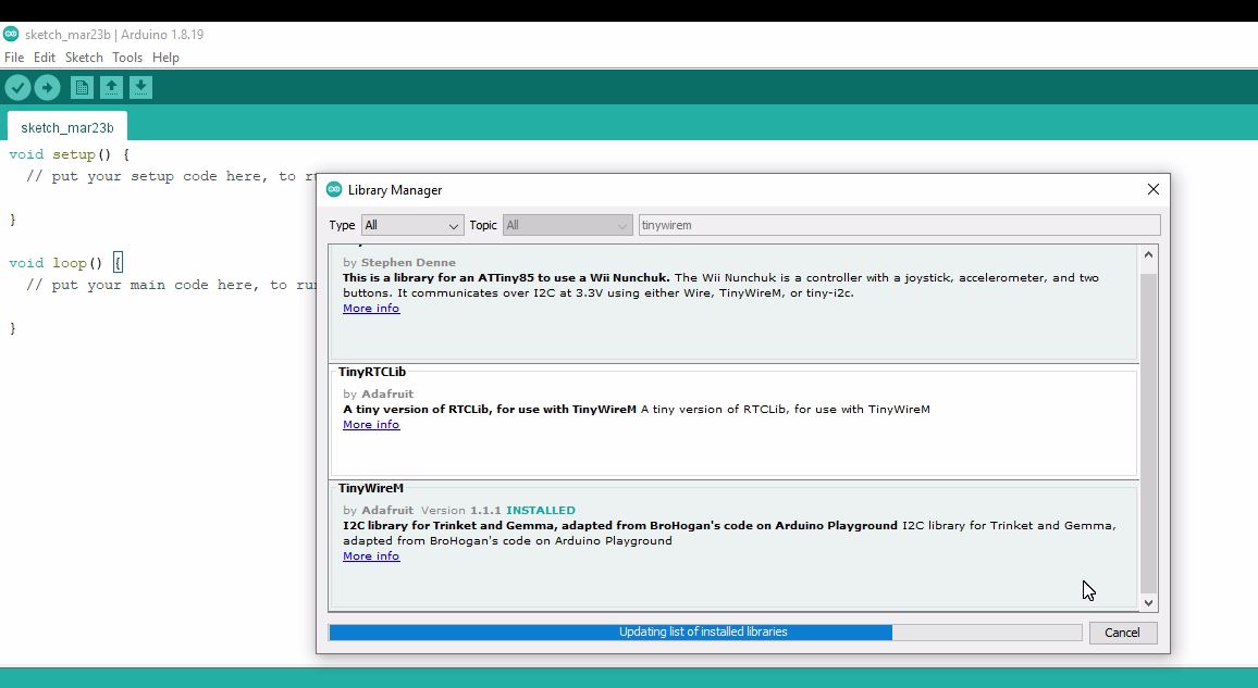
Next, we are going to install the TinyWireM library. This is the one I am going to install. The TinyWireM library has been installed.
Next we are going to install the Tiny4kOLED library. This is the library that we need to install and as you can see this library is created for an ATtiny85 to use an I2C supported SSD1306 Oled display module. So, let’s go ahead and install this library.

The library has been installed. I am also going to install the TinyOLED-Fonts library, although I don’t need this library, but as this library has a collection of fonts; so, I think, I may need this library.

All the libraries are installed and now let’s take a look at the programming.
Programming:
|
1 2 3 4 5 6 7 8 9 10 11 12 13 14 15 16 17 18 19 20 21 22 23 24 25 26 27 28 29 30 31 32 33 34 35 36 37 38 39 40 41 42 43 44 45 46 47 48 49 50 51 52 53 54 55 56 57 58 59 60 61 |
#include <dht.h> #include <TinyWireM.h> #include <Tiny4kOLED.h> #define DHT21_PIN PB1 const unsigned char img_thermometer[] PROGMEM = { 0x00, 0xfe, 0x03, 0xfe, 0x50, 0x00, 0xff, 0x00, 0xff, 0x55, 0x60, 0x9f, 0x80, 0x9f, 0x65, }; dht DHT; float getTemperature() { return DHT.temperature; } float getHumidity() { return DHT.humidity; } void setup() { pinMode(DHT21_PIN, INPUT); oled.begin(128, 64, sizeof(tiny4koled_init_128x64br), tiny4koled_init_128x64br); // Two fonts are supplied with this library, FONT8X16 and FONT6X8 oled.setFont(FONT8X16); // To clear all the memory oled.clear(); oled.on(); delay(3000); } void loop() { static long startTime = 0; long currentTime; DHT.read22(DHT21_PIN); // Get current time currentTime = millis(); // Checks 1 second passed if ((currentTime - startTime) > 1000) { startTime = currentTime; // Update temperature float temperature = getTemperature(); // Set cursor oled.setCursor(15, 4); oled.print("Temp: "); // Print to display oled.print(temperature, 1); oled.print(" °C "); // Update humidity float humidity = getHumidity(); // Set cursor oled.setCursor(15, 6); oled.print("Humi: "); // Print to display oled.print(humidity, 1); oled.print(" % "); oled.bitmap(2, 5, 7, 8, img_thermometer); } } |
I have added the required libraries. The DHT21 Data wire is connected to the PB1 pin which is the physical pin number 6 or the digital Pin1.
|
1 2 3 4 5 |
const unsigned char img_thermometer[] PROGMEM = { 0x00, 0xfe, 0x03, 0xfe, 0x50, 0x00, 0xff, 0x00, 0xff, 0x55, 0x60, 0x9f, 0x80, 0x9f, 0x65, }; |
This part of the code is to display the thermometer icon on the Oled Display module. And then the rest of the code is almost the same.
Now, the final step is to upload this program. As you know, the ATtiny85 has no USB support so we will need to use an Arduino board to upload the program. So, next I am going to explain how to connect your ATtiny85 with the Arduino Uno.

Connect pin 1 of the ATtiny85 which is also the reset pin to pin 10 of the Arduino which is the SS (Slave Select).
Connect pin 4 which is the ground pin to the Ground pin of the Arduino.
Connect pin 5 which is the MOSI pin to pin 11 of the Arduino which is the MOSI (Master-out, Slave In).
Connect pin 6 which is the MISO pin to pin 12 of the Arduino which is the MISO (Maser-In, Slave Out).
Connect pin 7 which is the SCK pin to pin 13 of the Arduino which is the SCK (Serial Clock).
Connect pin 8 of the ATtiny85 which is the VCC pin to the Arduino 5V pin.
Finally, connect a 10uF capacitor between the Reset and GND pins of the Arduino. Make sure you connect the +Ve leg of the capacitor with the Reset pin and the other leg of the capacitor with the GND. So, that’s all about the connections.
Connect Arduino Uno with the Laptop and Upload this program. But first, you will need to add the ATtiny85 controller in the Arduino IDE.
ATtiny85 in Arduino IDE:
The ATtiny85 microcontroller is not pre-installed in the Arduino IDE and you can confirm this by going to the Tools Menu and then to board, you will see a long list of the Arduino boards, but you won’t find ATtiny85. So, this means you will have to manually install the ATtiny85 as a board in the Arduino IDE.
For this, copy the board manager URL link given below.
https://raw.githubusercontent.com/damellis/attiny/ide-1.6.x-boards-manager/package_damellis_attiny_index.json
Then come back to the Arduino IDE, go to the File Menu, and then to Preferences, and paste the link in the Additional Boards Manager URLs.

Put a comma if you have added other boards otherwise you can directly paste the board URL link and then click on the OK button.
Go to the Tools Menu, then to board, and click on the Boards Manager. Search for the ATtiny and install it.

You can see the ATtiny85 is included in this boards Package. Anyway, you can see I have already installed this board.
Now, to confirm that the ATtiny85 Microcontroller is added, go to the Tools Menu, then to Board and you can see the ATtinny Microcontrollers.

You can see different variants of the ATtiny microcontrollers. So, let’s go ahead and select the ATtiny85 controller.
Now, let’s go ahead and upload the program.
Note: Make sure you have installed the Bootloader on the ATtiny85; if not then read my getting started article on the ATtiny85.

Everything looks good and now let’s power up this project.
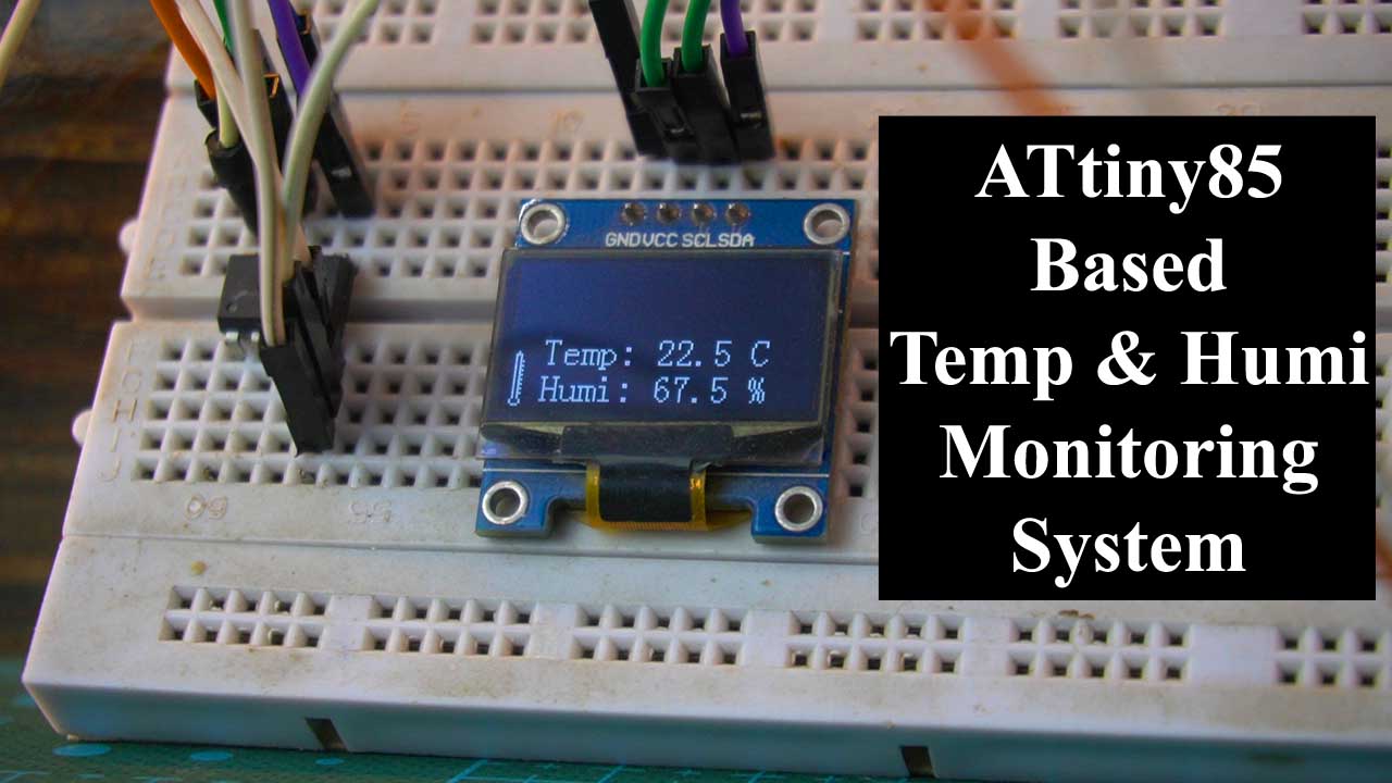
I was able to monitor the Temperature and Humidity % on the SDD1306 OLED display Module. Next, I applied temperature, as you can see rise in the temperature.
For practical demonstration, watch the video tutorial given below.
Watch Video Tutorial:

Discover more from Electronic Clinic
Subscribe to get the latest posts sent to your email.
very helpful and informative .
The ATTiny85 has no use for a bootloader if you never use USB (through PB3 and PB4) to directly reprogram it.
Your addition of the line:
#include
…is completely wasted. Nothing in that header is visible to any files except this .ino file. Tiny4kOLED can’t see it, and DHT can’t see it.
That isn’t how C/C++ works.
If you want Tiny4kOLED to use TinyWireM, then you have to add TinyWire support to Tiny4kOLED, not to this sketch.
Having issues with it “hanging” and getting stuck on the same readings after about an hour (maybe more). I’ve added a clear to the loop area just to make sure it is looping. It is, but it does eventually hang.
Any suggestions?