ESP32 E-Ink Temperature Display Using ESP-NOW Wireless Communication
Last Updated on March 9, 2026 by Engr. Shahzada Fahad
Table of Contents
Description:
Developing a reliable, low-power environmental monitor requires more than just a sensor; it requires the right communication architecture. In this guide, we deploy a Wireless ESP32 E-Ink Temperature Display designed for maximum efficiency. By integrating the Makerfabs 4.2-inch triple-color ePaper display with ESP-NOW and WiFi IP protocols, I’ll show you how to build a robust, real-world monitoring system that maintains data visibility without a constant power source.
In our previous guide, we took a deep dive into this display, covering how to load images, write text, and even how to print a numeric value.
Honestly, the performance was impressive. What struck me most was how much it behaves like real paper; I turned off the lights, it disappeared exactly like real paper, and when I turned the lights back on, it came back just like a printed sheet. That’s the real beauty of E-Ink technology.
And this specific feature, holding the image even after power is completely removed, makes it perfect for today’s project. Because once a temperature reading is printed on the display, the power usage drops to almost zero. Even a tiny Li-Po battery can last for months.
Now, you could just plug the sensors directly into this board; that’s the easy route. But today, I want to show you a completely different, more scalable approach.
Amazon Links:
Other Tools and Components:
ESP32 WiFi + Bluetooth Module (Recommended)
Arduino Nano USB C type (Recommended)
*Please Note: These are affiliate links. I may make a commission if you buy the components through these links. I would appreciate your support in this way!
Let’s imagine a real scenario:
Your temperature sensor is installed outdoors, and your E-Ink display is indoors.
So the data has to be sent wirelessly… and that’s exactly what we are going to do.
Today, I will show you two wireless techniques to send temperature readings:
Number 1: ESP-NOW; ultra low-power, direct, device-to-device communication.
Number 2: Through IP Address; using WiFi network connectivity.
So, whether you want a local, battery-powered setup or a WiFi-connected smart home system, both options are covered.
Before we jump in, all the important libraries, board settings, and setup steps were already explained in the previous article.
I am not going to repeat them here; so if you missed that article, definitely read it. It will help you follow along with zero confusion.
Now, let’s talk about the transmitter side.
I am using a regular ESP32 Dev Module, and the DS18B20 waterproof one-wire digital temperature sensor.
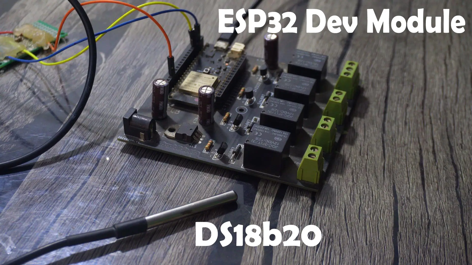
The wiring is extremely simple.
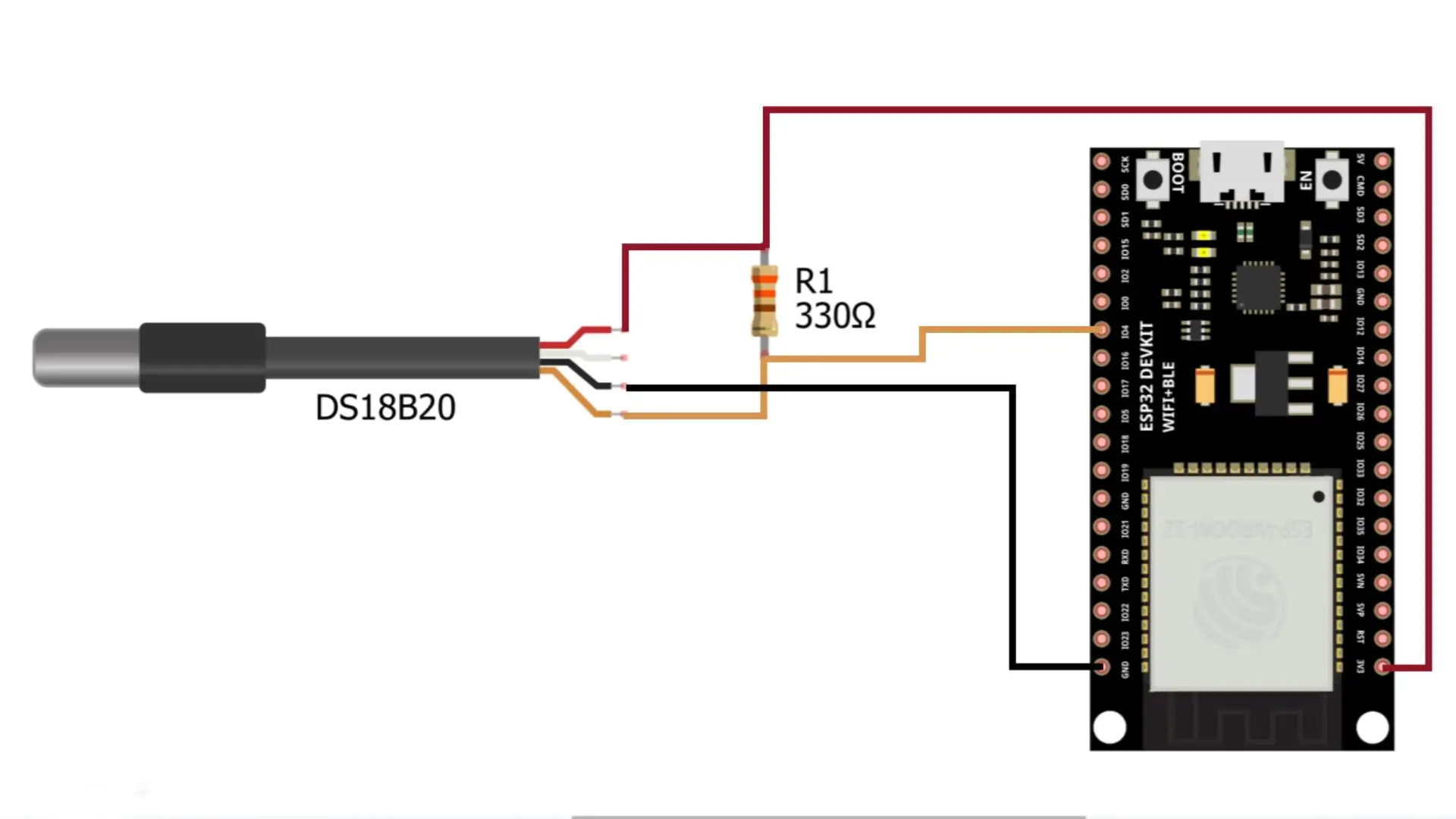
The Data wire goes to GPIO 4.
VCC goes to 3.3 volt.
And GND goes to the ESP32 ground pin.
That’s it.
Next, let me show you the two programs we will be using for this project.
If you want the full project folders and all supporting resources, you can download everything from my Patreon page.
ESP-NOW Programming:
This first one is the ESP-NOW transmitter code.
As you can see, the DS18B20 temperature sensor is connected to GPIO 4, and this program simply reads the temperature and sends it wirelessly to the receiver.
Transmitter Code:
|
1 2 3 4 5 6 7 8 9 10 11 12 13 14 15 16 17 18 19 20 21 22 23 24 25 26 27 28 29 30 31 32 33 34 35 36 37 38 39 40 41 42 43 44 45 46 47 48 49 50 51 52 53 54 55 56 57 58 59 60 61 62 63 64 65 66 67 68 69 70 71 72 73 74 75 76 77 |
#include <WiFi.h> #include <esp_now.h> #include <OneWire.h> #include <DallasTemperature.h> // ================= DS18B20 Sensor ================= const int oneWireBus = 4; OneWire oneWire(oneWireBus); DallasTemperature sensors(&oneWire); // ================= ESP-NOW RECEIVER MAC ================= // MAC address of the ESP32-S3 (receiver) uint8_t receiverMAC[] = {0x3C, 0x84, 0x27, 0xC0, 0xE8, 0xBC}; // Data structure to send typedef struct struct_message { float temperature; } struct_message; struct_message dataToSend; // Callback: when data is sent void OnDataSent(const uint8_t *mac_addr, esp_now_send_status_t status) { Serial.print("Send Status: "); Serial.println(status == ESP_NOW_SEND_SUCCESS ? "Success" : "Fail"); } void setup() { Serial.begin(115200); // Start DS18B20 sensors.begin(); // Must set WiFi to station mode for ESP-NOW WiFi.mode(WIFI_STA); Serial.print("Sender MAC Address: "); Serial.println(WiFi.macAddress()); // Init ESP-NOW if (esp_now_init() != ESP_OK) { Serial.println("ESP-NOW init failed!"); ESP.restart(); } Serial.println("ESP-NOW Initialized."); // Register send callback esp_now_register_send_cb(OnDataSent); // Register peer esp_now_peer_info_t peerInfo = {}; memcpy(peerInfo.peer_addr, receiverMAC, 6); peerInfo.channel = 0; peerInfo.encrypt = false; if (esp_now_add_peer(&peerInfo) != ESP_OK) { Serial.println("Failed to add peer!"); return; } Serial.println("Peer added successfully."); } void loop() { // Read temperature sensors.requestTemperatures(); float tempC = sensors.getTempCByIndex(0); Serial.print("Temperature: "); Serial.println(tempC); // Prepare data dataToSend.temperature = tempC; // Send using ESP-NOW esp_now_send(receiverMAC, (uint8_t *)&dataToSend, sizeof(dataToSend)); delay(1000); // send every 1 second } |
And this other one here is the receiver code.
Its job is to listen for the incoming ESP-NOW packets and then print the received temperature value on the E-Ink display.
Receiver Code:
|
1 2 3 4 5 6 7 8 9 10 11 12 13 14 15 16 17 18 19 20 21 22 23 24 25 26 27 28 29 30 31 32 33 34 35 36 37 38 39 40 41 42 43 44 45 46 47 48 49 50 51 52 53 54 55 56 57 58 59 60 61 62 63 64 65 66 67 68 69 70 71 72 73 74 75 76 77 78 79 80 81 82 83 84 85 86 87 88 89 90 91 92 93 94 95 96 97 98 99 100 101 102 103 104 105 106 107 108 109 110 111 112 113 114 |
#include "DEV_Config.h" #include "EPD.h" #include "GUI_Paint.h" #include <esp_now.h> #include <WiFi.h> #define SCREEN_W 400 #define SCREEN_H 300 #define REFRESH_INTERVAL_MIN 2 // refresh every 3 minutes UBYTE *BlackImage, *RYImage; float latestTemperature = -100.0; unsigned long lastUpdateTime = 0; unsigned long refreshInterval = REFRESH_INTERVAL_MIN * 60 * 1000UL; // ------------------------------------ // ESP-NOW Data Structure typedef struct struct_message { float temperature; } struct_message; struct_message incomingData; // ------------------------------------ // ======== DATA RECEIVED CALLBACK ======== void onReceive(const uint8_t * mac, const uint8_t *incomingDataBytes, int len) { memcpy(&incomingData, incomingDataBytes, sizeof(incomingData)); latestTemperature = incomingData.temperature; Serial.print("ESP-NOW Received: "); Serial.println(latestTemperature); } // ======== SETUP ======== void setup() { USBSerial.begin(115200); USBSerial.println("ESP32-S3 E-Ink ESP-NOW Receiver Starting..."); DEV_Module_Init(); eink_init(); WiFi.mode(WIFI_STA); USBSerial.println("MAC Address: "); USBSerial.println(WiFi.macAddress()); ////// 3C:84:27:C0:E8:BC WiFi.disconnect(); if (esp_now_init() != ESP_OK) { USBSerial.println("ESP-NOW Init Failed!"); return; } esp_now_register_recv_cb(onReceive); displayText("Waiting for ESP-NOW..."); lastUpdateTime = millis(); } // ======== LOOP ======== void loop() { // Update screen every 3 minutes if (millis() - lastUpdateTime >= refreshInterval) { updateDisplay(latestTemperature); lastUpdateTime = millis(); } } // ======== E-INK INITIALIZATION ======== void eink_init() { USBSerial.println("E-Ink Init..."); EPD_4IN2B_V2_Init(); EPD_4IN2B_V2_Clear(); delay(500); long Imagesize = SCREEN_W * SCREEN_H / 8; BlackImage = (UBYTE *)malloc(Imagesize); RYImage = (UBYTE *)malloc(Imagesize); Paint_NewImage(BlackImage, SCREEN_W, SCREEN_H, 0, WHITE); Paint_NewImage(RYImage, SCREEN_W, SCREEN_H, 0, WHITE); } // ======== DISPLAY TEXT FUNCTION ======== void displayText(String message) { Paint_SelectImage(BlackImage); Paint_Clear(WHITE); Paint_SelectImage(RYImage); Paint_Clear(WHITE); Paint_SelectImage(RYImage); Paint_DrawString_EN(45, 80, "ESP32S3 RECEIVER", &Font24, WHITE, RED); Paint_SelectImage(BlackImage); Paint_DrawString_EN(50, 150, message.c_str(), &Font24, BLACK, WHITE); EPD_4IN2B_V2_Display(BlackImage, RYImage); delay(2000); } // ======== UPDATE DISPLAY EVERY 3 MINUTES ======== void updateDisplay(float temp) { char msg[64]; if (temp < -50) { sprintf(msg, "No Data"); } else { sprintf(msg, "Temp: %.2f C", temp); } EPD_4IN2B_V2_Init(); displayText(String(msg)); EPD_4IN2B_V2_Sleep(); } |
Now, I am not going to explain how ESP-NOW works internally; because I have already explained all of that in my previous video and article, in complete detail.
So, here’s what you need to do: upload the receiver code first, open the Serial Monitor, and copy the MAC address.

Then open the transmitter code, paste the MAC address with the ‘0x’ prefix, and finally upload the transmitter code.
I have already uploaded both programs, so let’s go ahead and watch them in action.
Practical Demonstration:

For testing purposes, I have set the update interval to 2 minutes.
So every two minutes, the temperature value is read from the sensor and then printed onto the E-Ink display.
And as you already know from my previous article, the printing process on an E-Ink display is a little slow; it takes a few seconds to refresh the screen.
But that’s completely normal, because E-Ink is not designed for fast animations; It’s designed for clarity, stability, and ultra-low power.
And honestly, that’s the beauty of this technology.

Once the value is printed, it just stays there; without consuming almost any power.
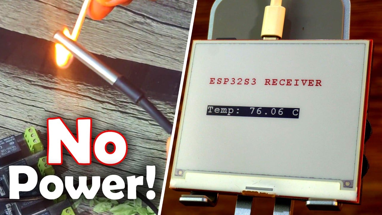
Now let me apply some heat to the temperature sensor.

Let’s wait for the value to update.
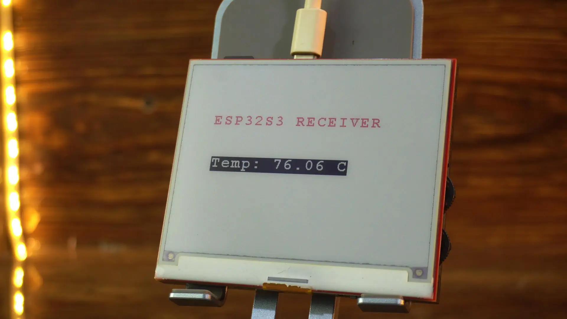
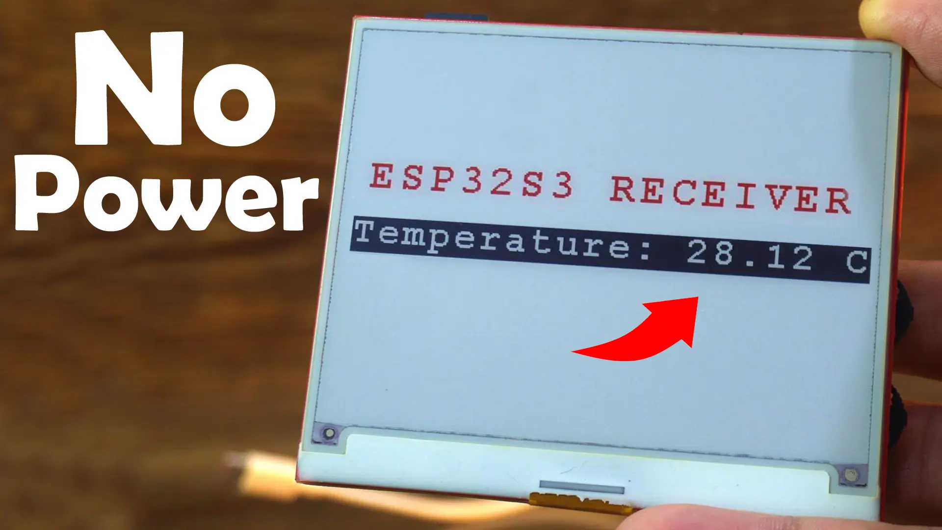
And there it is; the E-Ink display has refreshed, and the new temperature value is now printed on the screen. Super clean, sharp, and completely readable from any angle.
Now watch this.
I am going to cut the power completely.

And as you can see; the temperature value is still there.
This is what makes E-Ink displays so incredible.
There’s no backlight, no refresh cycles, no power drain; Just a stable, paper-like image that stays visible even with zero power.
Honestly, this is one of those things that never stops amazing me.
Imagine using a tiny Li-Po battery and still getting months of operation.
For off-grid sensors, weather stations, meters, timers; this is absolutely perfect.
Alright, now that we have tested the ESP-NOW version successfully. Let’s take a look at the second method; sending temperature data through the IP address.
IP Address Method:
This is the transmitter-side code.
You can see the temperature sensor is still connected to GPIO 4, just like before.
Transmitter Code:
|
1 2 3 4 5 6 7 8 9 10 11 12 13 14 15 16 17 18 19 20 21 22 23 24 25 26 27 28 29 30 31 32 33 34 35 36 37 38 39 40 41 42 43 |
#include <WiFi.h> #include <OneWire.h> #include <DallasTemperature.h> // GPIO where the DS18B20 is connected to const int oneWireBus = 4; // Setup a oneWire instance to communicate with any OneWire devices OneWire oneWire(oneWireBus); // Pass our oneWire reference to Dallas Temperature sensor DallasTemperature sensors(&oneWire); const char* WIFI_SSID = "fahad"; const char* WIFI_PASS ="fahad123"; const char* HOST = "10.11.106.75"; // <-- change to receiver’s IP address const int PORT = 80; void setup() { Serial.begin(115200); // Start the DS18B20 sensor sensors.begin(); WiFi.begin(WIFI_SSID, WIFI_PASS); while (WiFi.status() != WL_CONNECTED) delay(500); Serial.println("Connected to WiFi"); } void loop() { sensors.requestTemperatures(); float temperature = sensors.getTempCByIndex(0); float temperatureF = sensors.getTempFByIndex(0); Serial.print(temperature); Serial.println("ºC"); Serial.print(temperatureF); Serial.println("ºF"); WiFiClient client; if (client.connect(HOST, PORT)) { client.println(String(temperature)); // send plain number, e.g., "24.8" Serial.println("Sent temperature: " + String(temperature)); } client.stop(); delay(1000); // send every 1 second } |
And this time, make sure you update the SSID, Password, and the IP address according to your own Wi-Fi network.
So here’s what you need to do:
First, upload the receiver-side code into the E-Ink display controller.
Receiver Code:
|
1 2 3 4 5 6 7 8 9 10 11 12 13 14 15 16 17 18 19 20 21 22 23 24 25 26 27 28 29 30 31 32 33 34 35 36 37 38 39 40 41 42 43 44 45 46 47 48 49 50 51 52 53 54 55 56 57 58 59 60 61 62 63 64 65 66 67 68 69 70 71 72 73 74 75 76 77 78 79 80 81 82 83 84 85 86 87 88 89 90 91 92 93 94 95 96 97 98 99 100 101 102 103 104 105 106 107 108 109 110 111 112 113 114 115 116 117 118 119 120 121 122 123 124 125 126 127 128 129 130 |
#include "DEV_Config.h" #include "EPD.h" #include "GUI_Paint.h" #include <WiFi.h> #include <WiFiClient.h> // ===================== USER SETTINGS ===================== #define SCREEN_W 400 #define SCREEN_H 300 #define REFRESH_INTERVAL_MIN 2 // e-ink refresh every 2 minutes const char* WIFI_SSID = "fahad"; const char* WIFI_PASS = "fahad123"; // ========================================================= UBYTE *BlackImage, *RYImage; WiFiServer server(80); float latestTemperature = -100.0; unsigned long lastUpdateTime = 0; unsigned long refreshInterval = REFRESH_INTERVAL_MIN * 60 * 1000UL; // ========================================================= void setup() { USBSerial.begin(115200); USBSerial.println("ESP32-S3 E-Ink Text Receiver Starting..."); DEV_Module_Init(); eink_init(); // Wi-Fi setup WiFi.mode(WIFI_STA); WiFi.begin(WIFI_SSID, WIFI_PASS); USBSerial.print("Connecting to WiFi"); while (WiFi.status() != WL_CONNECTED) { delay(500); USBSerial.print("."); } USBSerial.println(); USBSerial.print("Connected! IP: "); USBSerial.println(WiFi.localIP()); server.begin(); displayText("Waiting for Data..."); lastUpdateTime = millis(); } // ========================================================= void loop() { WiFiClient client = server.available(); if (client) { USBSerial.println("Client connected!"); String requestData = ""; while (client.connected()) { while (client.available()) { char c = client.read(); if (c == '\n') { // Save latest received value (but DO NOT refresh display yet) latestTemperature = requestData.toFloat(); USBSerial.print("Received: "); USBSerial.println(latestTemperature); client.println("ACK"); client.stop(); break; } else { requestData += c; } } } } // === REFRESH EVERY 3 MINUTES ONLY === if (millis() - lastUpdateTime >= refreshInterval) { USBSerial.println("2-minute refresh triggered."); updateDisplay(latestTemperature); lastUpdateTime = millis(); } } // ============================================================ // ================= DISPLAY INITIALIZATION =================== void eink_init() { USBSerial.println("E-Ink Init..."); EPD_4IN2B_V2_Init(); EPD_4IN2B_V2_Clear(); delay(500); long Imagesize = SCREEN_W * SCREEN_H / 8; BlackImage = (UBYTE *)malloc(Imagesize); RYImage = (UBYTE *)malloc(Imagesize); Paint_NewImage(BlackImage, SCREEN_W, SCREEN_H, 0, WHITE); Paint_NewImage(RYImage, SCREEN_W, SCREEN_H, 0, WHITE); } // ============================================================ // ================= DISPLAY FUNCTIONS ======================== void displayText(String message) { Paint_SelectImage(BlackImage); Paint_Clear(WHITE); Paint_SelectImage(RYImage); Paint_Clear(WHITE); // Title (red) Paint_SelectImage(RYImage); Paint_DrawString_EN(45, 80, "ESP32S3 RECEIVER", &Font24, WHITE, RED); // Value (black) Paint_SelectImage(BlackImage); Paint_DrawString_EN(50, 150, message.c_str(), &Font24, BLACK, WHITE); EPD_4IN2B_V2_Display(BlackImage, RYImage); delay(2000); } void updateDisplay(float temp) { char msg[64]; if (temp < -50) sprintf(msg, "No Data"); else sprintf(msg, "Temperature: %.2f C", temp); EPD_4IN2B_V2_Init(); // wake display displayText(String(msg)); EPD_4IN2B_V2_Sleep(); // sleep to save power } |
Once the upload is complete, open the Serial Monitor, and you will see the IP address assigned to the board.

Simply copy that IP address… then open the transmitter code and paste it in the correct place.
Once that’s done, go ahead and upload the transmitter code as well.

And from this point onward, everything works exactly the same way.
The transmitter keeps sending the temperature value over your local network, and the ESP32-S3 on the receiver side prints that value onto the E-Ink display — clear, sharp, and paper-like, just the way E-Ink is meant to be.
It’s fast, reliable, and honestly pretty fun to watch because the entire system feels like a proper real-world wireless monitoring setup.
So, that’s all for now.
Watch Video Tutorial:
Discover more from Electronic Clinic
Subscribe to get the latest posts sent to your email.