DIY One transistor Class A Audio Amplifier using 2SC5200
Last Updated on August 23, 2024 by Engr. Shahzada Fahad
Table of Contents
Description:
DIY One transistor Class A Audio Amplifier using 2SC5200– In this tutorial you will learn how to make a single transistor Audio amplifier using 2SC5200 Transistor. This transistor is suitable for use in 100W high fidelity audio amplifier’s output stage. You can power up the Speaker and audio amplifier using a 12v battery, a solar panel, Lithium-Ion cells, 110/220Vac to 12vdc adaptor. This is completely portable; you can use this small audio amplifier circuit with mobile phones, small mp3 players, laptops, and so on.
I am planning to use this Audio amplifier in my upcoming projects.
- DIY MP3 Player.
- Video Player.
- Announcement system.
- FM Radio transmitter and Receiver
- Laser based Spying gadget and so on.
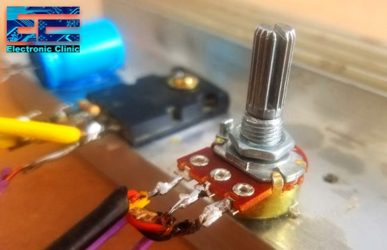
You can also add a potentiometer if you want to control the sound level, but I think it’s better not use the potentiometer as we can control the volume directly from the cell phone or mp3 players. Moreover you can save some money; the circuit connections will be reduced, the circuit size will be reduced.
This circuit is extremely cheap and needs only a few electronic components.
Few electronic components:
-
2SC5200 Transistor:
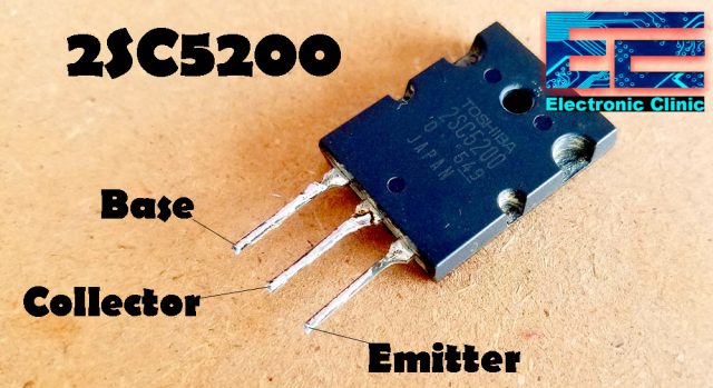
2SC5200 first leg is the Base, middle leg is the Collector, and the rightmost leg is the Emitter.
- High breakdown voltage: VCEO = 230 V (min)
- Complementary to 2SA1943
2SC5200 Maximum ratings (Tc = 25 centigrade)
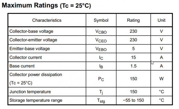
Download 2SC5200 Datasheet: 2sc5200 datasheet
-
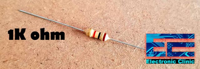
1K ohm resistor
-
A capacitor, 25v and 470uf.
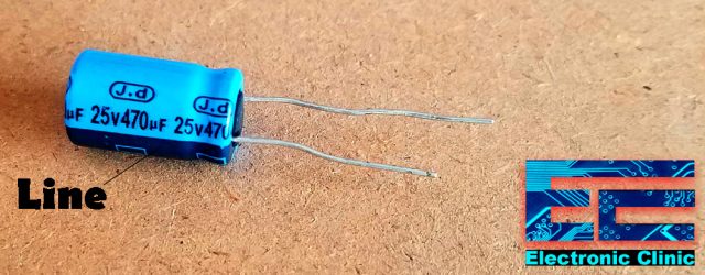
This is an electrolyte capacitor. The longer leg is the +ve while the shorter leg is the ground. if in case both the legs are of the same length, then the leg on the line side will be the ground leg.
-
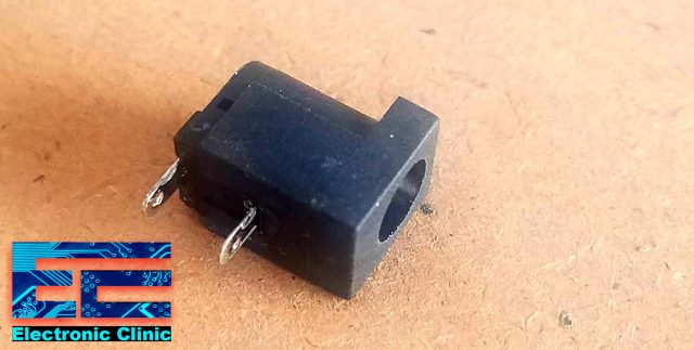
A DC female power jack
-
A Heatsink
Without any further delay let’s get started!!!
Amazon Links:
Disclosure: These are affiliate links. As an Amazon Associate I earn from qualifying purchases.
2SC5200 Audio Amplifier Circuit Diagram:
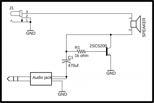
As you can see the Circuit Diagram is very simple. The two wires of the Speaker are connected with the input supply Dc female power jack and the collector of the 2SC5200 transistor. A 1K ohm resistor is connected between the collector and base of the 2SC5200 Transistor. While the emitter of the 2SC5200 is connected with the ground. The positive leg of the 470uf capacitor is connected with the 1k ohm resistor while the ground leg of the capacitor is connected with the two input wires of the Audio Jack. The ground wire of the audio jack should be connected with the supply ground.
Audio Amplifier components soldering:
I fixed the 2SC5200 transistor and the 470uf capacitor on the Heatsink and completed the soldering job as per the circuit diagram already explained.
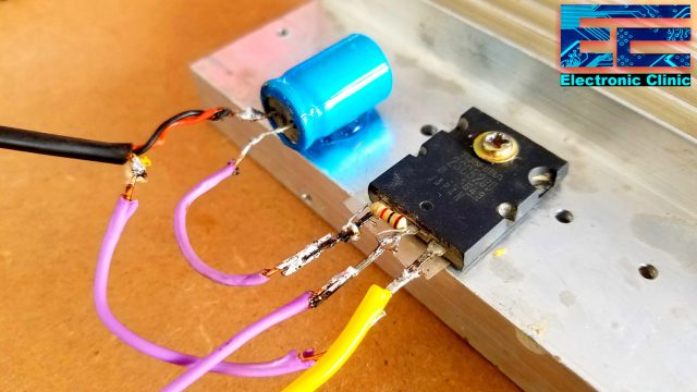
This is how the final audio amplifier circuit looks. Now all you need is simply power up the circuit using a 12v adaptor, battery, or a solar panel. Connect the cell phone and finally select a song you want to play.
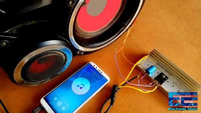
For the practical demonstration watch video given below. Don’t forget to subscribe to my Website and my YouTube channel “Electronic Clinic”. Support my channel by liking and sharing videos.
Watch Video Tutorial:
Discover more from Electronic Clinic
Subscribe to get the latest posts sent to your email.


I have a powered subwoofer but the electronics went out. Would this circuit be good to take the subwoofer output from my receiver and drive the subwoofer?
No. It has only few watts
But you have dc going straight into the speaker. This is wrong.