DMG80480C043_02WTC Touch Screen Getting started Tutorial
Last Updated on February 24, 2024 by Engr. Shahzada Fahad
Table of Contents
DMG80480C043_02WTC Touch Screen:
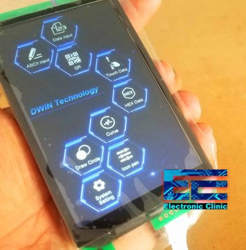
Recently I got these 4 smart touch screens from the DWIN technologies specialized in making High quality and cost effective HMI touch screens. The one on the bottom side is the Android touch screen, the one on the top side can be used with PLCs, the one the left side is the smart home temperature controller, and the DMG80480C043_02WTC one is my most favorite one and can be easily used with 5V compatible controller boards like Arduino Uno, Arduino Nano, Arduino Mega, PIC microcontrollers, 8051 family of microcontrollers, etc. So, in this tutorial, I am going to start with this touch screen.
Note:
Watch The Video Tutorial given at the end of this article.
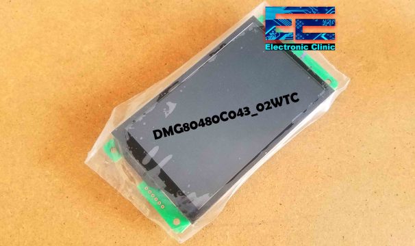
This is the DMG80480C043_02WTC cost effective touch screen and is based on the T5L DGUS Development System. DGUS stands for DWIN Graphic Utilized Software. Using the DGUS software tool amazing GUIs can be designed without even writing a single line of code. I will talk about this in detail while explaining the GUI.
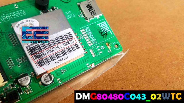
The DWIN smart LCMs follow a naming rule, DMG80480C043_02WTC,
- The first two characters DM represent the Product line code.
- The 3rd Character represents the color code, for this touch screen G means 16.7M color.
- The next 5 digits represent the touch screen resolution, for this touch screen 80480 means this is 800×480.
- The next character represents the Classification, for this touch screen C means commerce grade.
- The next three digits represent the size of the DWIN Smart LCMs, for this touch screen 043 means it’s a 4.3 inch touch screen.
- The underscore sign you can see, is the separator
- The next one digit or character represents the Attribute code, for this smart LCM 0 means the basic type.
- This one digit “the dark Yellow one” represents the ROM ID and it can be any digit from 0 to 9 to distinguish between different hardware versions.
- The next one character represents the LCD temperature grade, for this LCD, W means wide temperature.
- The final 1 or 2 characters represents the TP category, for this touch screen, TC means capacitive touch panel.
So we can say the DMG80480C043_02WTC is a 4.3 inch, 800×480 resolution, commerce grade, basic T5L smart LCM with capacitive touch panel.
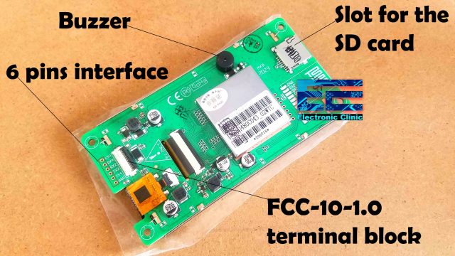
On the back of DMG80480C043_02WTC smart touch screen we have a slot for the micro SD card used to download the project files. A buzzer is also available which is programmable means it can be turned ON and turned OFF as per the requirements.
6 pins interface allows you to connect this smart touch screen with 5V controller boards using the TX and RX and 5V power supplies. The minimum voltage is 4.5V and the maximum voltage is 5.5V. I highly recommend use regulated 5 Volts power supply. When the Backlight is ON it draws around 230mA and when the Backlight is off it draws around 80mA. Recommended power supply as per the manufacturer is 5V and 1A.
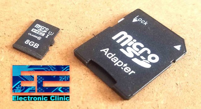
This smart touch screen “DMG80480C043_02WTC “is also provided with an 8GB micro SD card and a micro SD Adapter. This micro SD card is used to download the project files. The SD card must be formatted using FAT32 otherwise you may get some errors while transferring the project files.

This smart LCD touch screen has the FCC-10-1.0 terminal block which is used to connect this touch screen with the computer or laptop using the HDL662B Adapter board, FCC1015A Cable, and the HDLUSB Cable.
Download Driver:
XR21X141X driver for HDL662B adapter board
Before you connect the DMG80480C043_02WTC touch screen with the laptop you will need to install a driver for the HDL662B adapter board if you want to upload the project files without using the SD card, and you will also need this driver for establishing serial communication with 3rd party software’s, if incase you want to send commands to the touch screen. I have already installed this driver.
After you are done with the driver installation, connect your Touch screen with the laptop. You might see some images or animations, if the company has already downloaded a project. So, if you can see some text or images on the touch screen then it’s in the working condition.
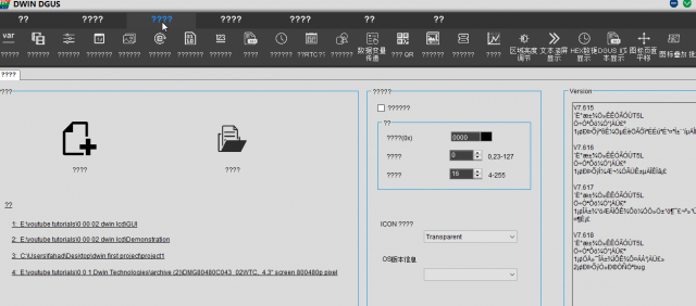
Next you can open the DGUS Software tool V7.618.
After you download and extract the DGUS_V7618 GUI development software too, open the folder and double click on the DGUS Tool V7.618.EXE file. By default the Chinese language is selected.
To change this to English language, go to the rightmost menu which is the settings menu.
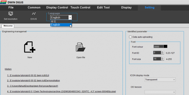
Click on the Language combo box and from the drop down menu select English.
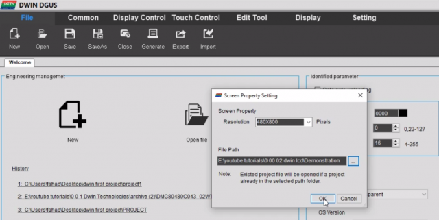
Next you can click on the new. Select the screen resolution as per your touch screen. I will select 480×800. Finally select the folder where you want to save your project files, and then click on the ok button.
Now you can start by adding your own designed images. On the left side you can see the Images View, click on the + button to add your images.
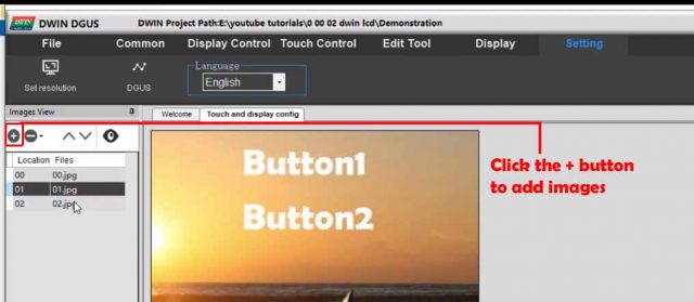
You can use the jpg and bmp type images with the names starting from 00 and so on. For the GUI designing you can use Adobe Photoshop, I added some text which I am going to use as the buttons, to switch between different images.
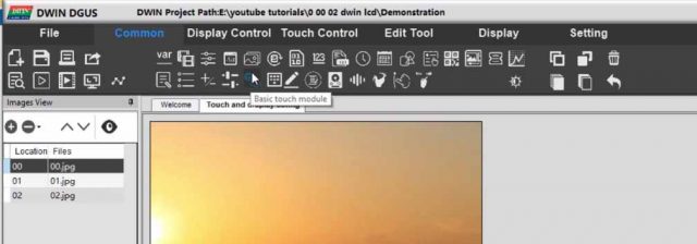
You have different modules for creating amazing animations, displaying number, texts, charts, etc, ready to be used; for the practice you can start with the basic touch module which is used to switch between different images.
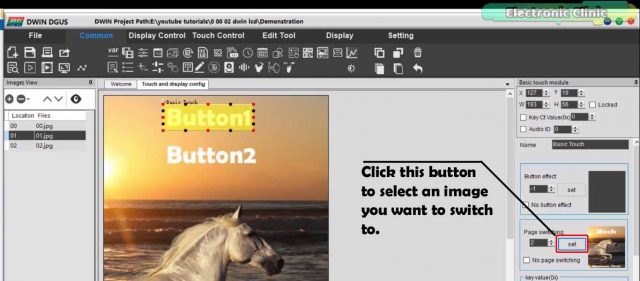
While the basic touch module is selected, simply draw a box around the text or any other area in the image, or the whole image which you want to use as the button, and then select the image you want to switch to, it’s that simple. You can randomly jump to any image you want, all you need to do is click on the set button on the right side, and select the image. You can repeat this process for all the images.
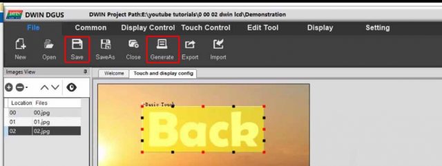
After you are done with all the settings, go to the file menu and again save your project and then click on the Generate button. Finally, go to the display menu and click on the preview from first page. This way you can check your designed system, this is a kind of simulation, you can click on the buttons, you will get the same feeling as if you are doing all this on the touch screen. So, now I am sure, you got the idea how GUI is designed. Instead of uploading this project, I am going to upload a project which I got from the DWIN technologies.
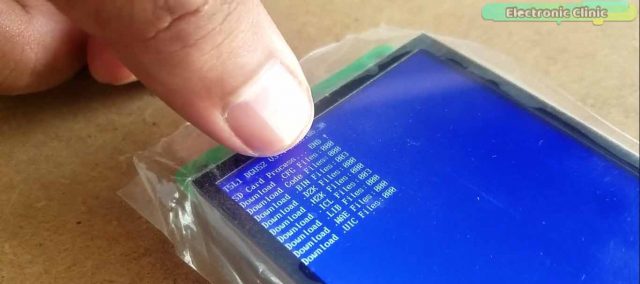
After you download the GUI zip folder, first extract the folder and then open click on the open and open the project file “DWprj.hmi”. They used a total of 100 images and used many modules, which you can study and this way you can find how they did it. Simply save the project and then click on the generate button. While your touch screen is connected with the Laptop, go to the settings menu and then click on the DGUS. A new window will open as you can see in the image given below.
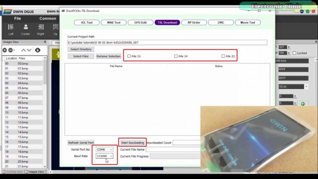
You should be able to see the serial port and the baud rate. Check all the three boxes “File 13, File 14, and File22” and finally click on the start downloading button and wait for a few seconds. The touch screen will automatically restart. You will see an animation switching between images automatically. You can click on the screen.
Another way to download the project files is to use the SD card. Copy and paste the project folder “DWIN_SET “, you can find this in the GUI folder. Turn off the LCD and insert the micro SD card. Turn on the touch screen, the project files downloading process will start and wait until you see the End!
Which means that the project is downloaded successfully. Again turn off the DMG80480C043_02WTC smart touch screen and remove the SD card, you don’t need it anymore as the project has be downloaded. Again turn ON your smart touch screen and you are good to go. You will see the same animation. Very soon I will use this smart capacitive touch screen with the Arduino board to display the sensors data and control different electrical loads.
Download the Related PDF files:
T5L_DGUSII Application Development Guide20200902 pdf
Watch Video Tutorial:
Discover more from Electronic Clinic
Subscribe to get the latest posts sent to your email.


I liked your tutorial. I build a small menu with just a few screens to learn the navigation. Putting buttons over some images I modified etc.
I have a problem that no one can answer in English. I upload the firmware folder and it loads but I never gets past 000_boot.bmp. My first image. I don’t understand what I’m missing.
I follow the tutorial, make a simple menu tree with some forward and back navigation. Simple. But I cannot get the screen to get past the 000_boot.bmp image. I’m uploading firmware with the micro SD formatted at 4024. Am I missing something?
I had faced the same issues then I had to contact the company and they send me the GUI. After all this, I didn’t use the same screen again. The HMI Screens by the Stone technologies are amazing.
I found your instruction and this helps me already to understand the device function. I have a complete different Idea to use that screen. maybe you can answer my following question to help me.
I have a 3D Printer where more or less the same device is used (Anycubic Vyper). I have modded the Printer with a different firmware hich is controlled now external via a Raspberry Pi4. The Display was used as touch control unit connected to the printer´s motherboard. currently it´s useless and only starts with the company Name in it.
And now to my question:
Is it possible take your explained connection (HDL662B Adapter board, FCC1015A Cable, and the HDLUSB Cable) to use the panel as “stupid” direct connected display + touch function @ my Raspberry?
Best regards,
Ralf
Can the project be refresh, that means if I make some amendment to the GUI, how do I reupload the project files?