Electric Boat Project using Arduino with wireless computer control system
Last Updated on August 18, 2024 by Engr. Shahzada Fahad
Table of Contents
Description:
Electric Boat Project using Arduino with wireless computer control system- In this tutorial, you will learn how to make an Electric Boat which can be controlled wirelessly using 433 MHz Radio Frequency Transmitter and Receiver modules using a computer application designed in Visual Basic. The wireless control system is based on short-range communication which works up to 15 meters. If you want long-range communication then you can simply replace these radio frequency Transmitter and Receiver modules with Lora Transceiver Modules whose communication range is up to 15 kilometers. Want to learn how to use 15km Lora Transceiver modules? Check the related projects section.
The computer application is very simple; you can use the Arrow keys on the keyboard to control the Forward, Left, and Right Movement of the Electric Boat. The same control system can be used in large size Electric boats.
The Electric Boat can be used in flood situation for rescuing humans and animals. It can be used for the security system, patrolling, etc. It’s totally up to you for what purpose you are going to use the Electric Boat.
A 12v battery is used to power up the Motors. A solar panel can be connected with the battery, which will make this Electric Boat as the Solar Electric Boat or Solar boat, etc. Wireless communication and motors controlling are done by the Arduino. The computer application will not work on the windows 10, the recommended one is windows 7 or XP.
Precautions: In this project, high-speed propellers are used, make sure you keep a safe distance when the motors are ON. Keep it away from children.
Amazon Links:
Arduino Nano USB-C Type (Recommended)
433 MHz Transmitter and Receiver Modules:
*Disclosure: These are affiliate links. As an Amazon Associate I earn from qualifying purchases.
Electric Boat Project Circuit diagram:
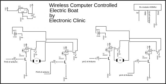
In this Electric Boat Project, two DC motors are used to control the Forward, Left, and Right movement using the computer application. These motors are controlled using the H-bridges. Two relays are wired up in such a way that it makes an H-bridge which can be used to control the forward and reverse movement of a DC motor. Each H-bridge consists of two relays.
Both the H bridges are exactly the same. The left side motor is controlled using the Arduino’s pin number 8 and pin number 9. While the right side motor is controlled using the Arduino’s pin number 2 and pin number 4. The relays used in this project are of the type SPDT “Single Pole Double Throw”.
The VCC and GND pins of the Receiver module are connected with the Arduino’s 5v and GND. While the data pin of the Receiver module is connected with the Arduino pin number 11.
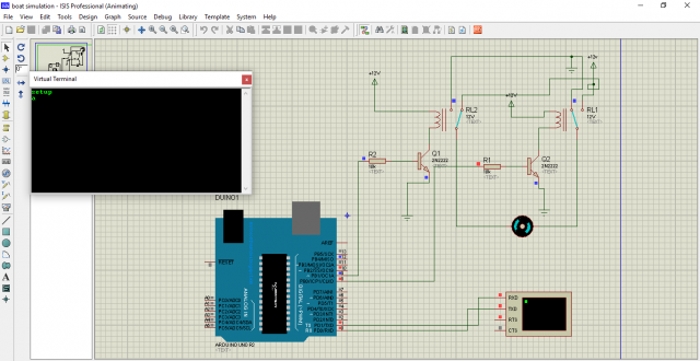
I tested the H bridge connections using the Proteus simulation and I successfully controlled the left and right movement.
Download H-Bridge simulation: H bridge simulation
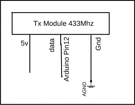
While on the Transmitter side only the Arduino and 433Mhz Transmitter module is used. The data pin of the Transmitter module is connected with the Arduino’s pin number 12, while the VCC and GND pins of the Transmitter module are connected with the Arduino’s 5v and GND.
Electric Boat Project Arduino Programming:
In this project two programs are used, one program is written for the Transmitter side and the other program is written for the Receiver side. Let’s first start with the Transmitter side programming.
Electric Boat Project Arduino Transmitter Programming:
|
1 2 3 4 5 6 7 8 9 10 11 12 13 14 15 16 17 18 19 20 21 22 23 24 25 26 27 28 29 30 31 32 33 34 35 36 37 38 39 40 41 42 |
#include <VirtualWire.h> #include <String.h> const int led_pin = 11; const int transmit_pin = 12; const int transmit_en_pin = 3; int ldr = A0; String str; char cstr[27]; void setup() { // Initialise the IO and ISR vw_set_tx_pin(transmit_pin); Serial.begin(9600); vw_setup(2000); // Bits per sec pinMode(led_pin, OUTPUT); pinMode(ldr, INPUT); } byte count = 1; void loop() { if(Serial.available()>0) { char message = Serial.read(); str = String(message); str.toCharArray(cstr,27); // msg[6] = count; digitalWrite(led_pin, HIGH); // Flash a light to show transmitting vw_send((uint8_t *)cstr, 1); // change this number according to the sensor values vw_wait_tx(); // Wait until the whole message is gone digitalWrite(led_pin, LOW); count = count + 1; } } |
Electric Boat Transmitter Arduino Program Explanation:
Before you start the programming, first of all, make sure that you download the virtual wire library by clicking on the download library.
Download Library:
The Transmitter module data pin is connected with the Arduino’s pin number 12… The void setup function consists of the same functions which I have already explained in my previous tutorial based on the 433 Mhz Radio Frequency TX and RX modules. In this tutorial, I have explained everything about how to use the Radiofrequency transmitter and receiver modules.
In the void loop function
if(Serial.available()>0) which means if the Arduino has received a command from the computer application, then simply read the serial port and store the received char in variable message. Convert this into a string and then convert this into an array of characters. Finally, this command is sent to the Receiver module wirelessly. Now let’s have a look at the receiver side programming.
Electric Boat Project Arduino Receiver Programming:
|
1 2 3 4 5 6 7 8 9 10 11 12 13 14 15 16 17 18 19 20 21 22 23 24 25 26 27 28 29 30 31 32 33 34 35 36 37 38 39 40 41 42 43 44 45 46 47 48 49 50 51 52 53 54 55 56 57 58 59 60 61 62 63 64 65 66 67 68 69 70 71 72 73 74 75 76 77 78 79 80 81 82 83 |
#include <VirtualWire.h> const int receive_pin = 11; int mright1 = 8; int mright2 = 9; int mleft1 = 2; int mleft2 = 4; void setup() { delay(1000); Serial.begin(9600); // Debugging only Serial.println("setup"); // Initialise the IO and ISR vw_set_rx_pin(receive_pin); vw_set_ptt_inverted(true); // Required for DR3100 vw_setup(2000); // Bits per sec vw_rx_start(); // Start the receiver PLL running pinMode(mright1, OUTPUT); pinMode(mright2, OUTPUT); pinMode(mleft1, OUTPUT); pinMode(mleft2, OUTPUT); digitalWrite(mright1, LOW); digitalWrite(mright2, LOW); digitalWrite(mleft1, LOW); digitalWrite(mleft2, LOW); } void loop() { uint8_t buf[VW_MAX_MESSAGE_LEN]; uint8_t buflen = VW_MAX_MESSAGE_LEN; if (vw_get_message(buf, &buflen)) // Non-blocking { int i; for (i = 0; i < buflen; i++) { char c = (buf[i]); Serial.print(c); if( c == '1') { digitalWrite(mright1, HIGH); digitalWrite(mright2, LOW); digitalWrite(mleft1, HIGH); digitalWrite(mleft2, LOW); } if( c == 'a') // left { digitalWrite(mright1, HIGH); digitalWrite(mright2, LOW); digitalWrite(mleft1, LOW); digitalWrite(mleft2, LOW); } if(c == 'b') // right { digitalWrite(mright1, LOW); digitalWrite(mright2, LOW); digitalWrite(mleft1, HIGH); digitalWrite(mleft2, LOW); } if(c == 's') { digitalWrite(mright1, LOW); digitalWrite(mright2, LOW); digitalWrite(mleft1, LOW); digitalWrite(mleft2, LOW); } } } } |
The receiver module data pin is connected with the Arduino’s pin number 11. The two H bridges are controlled using the Arduino’s pin 8, 9, 2, and 4…In the void loop function the received character is stored in variable c and then using the if conditions the left and right propellers are controlled accordingly.
Electric Boat Project Computer Application Programming:
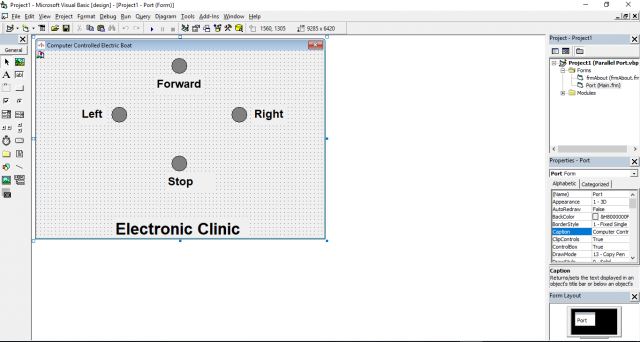
This is the computer application designed in visual basic.
Download application: vb application
|
1 2 3 4 5 6 7 8 9 10 11 12 13 14 15 16 17 18 19 20 21 22 23 24 25 26 27 28 29 30 31 32 33 34 35 36 37 38 39 40 41 42 43 44 45 46 47 48 49 50 51 52 53 54 55 56 57 58 59 60 61 62 63 64 65 66 |
Option Explicit Dim Value As Integer Dim PortAddress As Integer Private Sub Form_KeyDown(KeyCode As Integer, Shift As Integer) Select Case KeyCode Case vbKeyUp MSComm1.Output = "1" Shape3.FillColor = &HFF00& Case vbKeyLeft MSComm1.Output = "a" Shape1.FillColor = &HFF00& Case vbKeyRight MSComm1.Output = "b" Shape2.FillColor = &HFF00& Case vbKeyDown MSComm1.Output = "s" Shape4.FillColor = &HFF00& End Select End Sub Private Sub Command3_Click() Dim a As String a = MsgBox("Do you want to Exit", vbOKCancel, "PASSWORD PROTECTED") End If End Sub Private Sub Command4_Click() frmAbout.Visible = True End Sub Private Sub Form_KeyUp(KeyCode As Integer, Shift As Integer) Shape1.FillColor = &H808080 MSComm1.Output = "s" Shape2.FillColor = &H808080 Shape3.FillColor = &H808080 Shape4.FillColor = &H808080 End Sub Private Sub Form_Load() With MSComm1 .CommPort = 5 .Settings = "9600,N,8,1" .Handshaking = comRTS .RTSEnable = True .DTREnable = True .RThreshold = 1 .SThreshold = 1 .InputMode = comInputModeText .InputLen = 0 .PortOpen = True 'must be the last End With End Sub |
Electric Boat Computer application explanation:
With the help of the arrow keys the left, right, and forward movement of the Electric Boat is controlled…When the up arrow key is pressed the character l is sent to the receiver, when the left arrow key is pressed the character a is sent, when the right arrow key is pressed the character b is sent to the receiver and similarly when the down arrow key is pressed the character s is sent to the receiver…
With MSComm1
.CommPort = 5
.Settings = “9600,N,8,1”
.Handshaking = comRTS
.RTSEnable = True
.DTREnable = True
.RThreshold = 1
.SThreshold = 1
.InputMode = comInputModeText
.InputLen = 0
.PortOpen = True ‘must be the last
End With
These instructions are used to set up the serial port. Make sure you select the right communication port and you select the same baud rate which you have used in the Arduino programming, otherwise the communication will not work.
Watch Video Tutorial:
Discover more from Electronic Clinic
Subscribe to get the latest posts sent to your email.


WHERE IS virtual wire library