Flood Monitoring System with SMS Alert using Arduino and GSM
Last Updated on August 18, 2024 by Engr. Shahzada Fahad
Table of Contents
Flood Monitoring System, Introduction:
Flood Monitoring System with SMS Alert using Arduino and GSM- Mostly floods occur due to the heavy rainfall, from the melting of ice and snow on mountains, or from the combination of all these when exceeds water carrying capacity of the Lake, River or Sea into which it flows. One of the major factors is the Geographical location that causes a flood to occur. Because of the Floods, precious lives including humans and animals, properties that worth millions are found destroyed.
Due to Floods, the roads are destroyed, road traffic becomes jam. The telecommunication systems are destroyed so that there left no way of communication. The diseases are spread, the Agricultural setup is so badly damaged that it takes a lot of time to bring it again into normal condition. There are thousands of situations hen the local people don’t have the knowledge of flood occurring, due to which the people never get a chance to shift to a safer place, due to which they lose their loved ones, their important stuff at home, the animals, etc.
One other major problem that is faced during the flood situations is that the people have no idea where to shift, which road they should select to move to a new location. Because in such a situation nobody exactly knows what is happening. If there was such type of a system that could inform the people in advance before the heavy disaster, the lives could be saved, because when flood increases it destroys the telecommunication system as well. So we need a much quicker and advance system to let the people know before the destruction occurs.
Amazon Links:
Arduino Nano USB-C Type (Recommended)
*Disclosure: These are affiliate links. As an Amazon Associate I earn from qualifying purchases.
FLOODS IN PAKISTAN:
- if we look back at 2003 flood, The Sindh province was so badly affected due to the monsoon rainfall which was above the normal and caused flooding in the province; While the Thatta District we could say was the worst hit where four hundred and four “404”mm that’s 15.9 inches rainfall caused flash floods in the whole district. Approximately 484 people embraced death and around 4476 villages in the entire province were badly affected. [1][2][3]
- In 2007, KPK “Khyber-Pakhtunkhwa province, The Sindh and coastal Balochistan were so badly affected because of the monsoon rainfall. These two provinces were affected by the CYCLONE YEMYIN in JUNE and then torrential rains in JULY and AUGUST, while KPK “khyber-Pakthunkhwa was affected due to the melting of glaciers companied by the heavy rainfall happened in the months of JULY and AUGUST. Around 130 people died and around 2000 were displaced in KPK in the month of July while 22 people died in AUGUST. while due to flash flood in Sindh and Balochistan about 815 people died. [4]
- In 2010, due to the massive flooding which was caused by the record-breaking rains hit KPK and Punjab and due to which almost all of Pakistan was badly affected. The number of people affected in this flood was greater than the combined total individuals affected by the 2004 Indian Ocean Tsunami, Haiti earthquake 2010 and the 2005 Kashmir earthquake.[5] Approximately two thousand “2000” individuals died in this flooding and nearly 20 Million were affected by it.[6]
- Another disaster that occurred in Sep 2012, in which more than 100 individuals died, and destroyed thousands of homes, and affected thousands of acres of arable land when severe rainfall battered KPK, Upper Sindh and Southern Punjab.
- In August 2013, about 80 people died.
- Similarly in Sep 2014 flooding due to the extreme rainfall in Azad Jammu and Kashmir as well as Jammu and Kashmir and in Punjab[7] created flooding in River Jhelum and River Chenab. [8]
There are so many other disasters due to the Flooding in Pakistan which I didn’t mention over here. The destruction that flood brings cannot be expressed in words, The person who suffers from this can understand, and the ones who lose their loved ones and end up in destroyed homes can have an idea about the flood. I myself never come across a situation like this, and there might be millions like me. So that’s why I decided to develop such kind of Flood monitoring system that can inform the different local areas government personnel in advance before the flooding brings unstoppable destruction to those millions and billions of people.
Flood Monitoring System Project Overview:
The Flood Monitoring System project is entirely based on the GSM sim900A or GSM sim900D module, which will be interfaced with the most popular microcontroller “ATmega328”, the same microcontroller which is used in Arduino Uno.
A water level monitoring sensor will also be connected with this microcontroller to keep track of the water level. At present, I have decided to use the Ultrasonic Sensor for this purpose. But as I am studying and thinking about an alternative sensor that can be much cheaper and reliable than this one, if I am succeeded in making my own sensor for this job then I will replace the Ultrasonic sensor with my designed water level monitoring sensor.
In this project, we will be having the main monitoring station, which will be consisting of a computer. In this computer, we will be having a monitoring application installed, which we will design. This computer will be then connected with the Arduino Uno through a USB cable, the Arduino Uno will be then interfaced with the GSM module to receive messages from the flood monitoring module installed in different areas of the province or Pakistan if this project is implemented at the country level. The messages received will be given to the computer application to display the water level and the area from where this message is sent. As this project is not at a prototype level, so I will have to keep all the factors in mind, like for example,
- The cost of each component
- Availability in Pakistani local market.
- durability
- size
- weight
- load
- manufacturability ” whether this can be manufactured in my own country or not”
- The enclosure designing
- The enclosure material.
- Cost per piece.
- My own Sensor designing that can withstand the rough conditions and can have much more accuracy than the Ultrasonic Sensor.
- cost reduction of PCB ” printed circuit board”
- Company establishment cost ” if we set up a company for this ” to even export to other countries.
- Maintenance cost.
- ambient temperatures ” that can affect the devices or not “
Tools used in Flood monitoring system:
- SolidWorks 2016
- Visual Basic ” For GUI application designing and programming”
- Proteus ” simulation”
- Arduino IDE ” c language programming”
- CadeSoft Eagle ” for schematics and PCB’s making”
Flood Monitoring System Project Objectives:
- Planning to start a business and helping the government and people around the world.
- Importing the GSM modules and other electronic equipment as needed.
- Simulation and assembling of the electronic devices.
- Coding in the GSM module by using Microsoft Visual Basic software.
- Perform economic Analyses for the business
Flood Monitoring System Project Problem Statement:
The main problem is how to protect the people from floods, how to stop the destruction caused by flooding still a question to be answered. Does the government need to invest millions in the technology to import monitoring systems from other countries?
A solution to the problem:
The main purpose of this project is to design such a project that can be implemented throughout Pakistan and other countries. But, as we know that implementation at such a large scale will result in a lot of money if we keep importing the PCBs, programs, enclosures, sensors, etc. So the solution to this problem is to design the majority of things ourselves by establishing a company. And only a few things can be imported from another country. The designing chapter will be consisting of all the information about the type of machines that will be used in manufacturing, the type of material and its cost, all the necessary information on the basis of which a new company can be started.
Flood Detector System using Arduino Uno
In this project the same ultrasonic sensor was used for the floodwater level monitoring, this project had no GUI application designed and no control room was there. This project was developed using the Arduino Uno and GSM.
International Journal of Management and Applied Science, ISSN: 2394-7926 Volume-2, Issue-7, Jul.-2016
The majority of the projects so far done almost uses the same techniques. Most of the projects make use of Ultrasonic sensors. None of these projects gave details about the cost analysis, the complete designing, safety, type of the enclosures, etc. As these projects were at the prototype level.
While this project is entirely different from the rest of the projects so far done. In this project, I will be using my own designed sensor which is more reliable, can be made locally, and most importantly it has zero percent error chance. Moreover, my project designing is at the province level, in which hundreds of monitoring systems will be installed at different locations, all these monitoring stations will then communicate with the main monitoring station with the help of the GSM module.
As my focus is on the business development. So, I will cover all the designing steps from schematics to final PCB’s, the enclosures, the material, cost, the dimensions, and the type of machine that will be needed. Besides this I will also develop my own controller board for the monitoring side so that the cost can be reduced. While in the main station Arduino Uno will be used. Later, I will show how much it will benefit if we will be using our own controller board.
Flood Monitoring System Circuit Diagram:
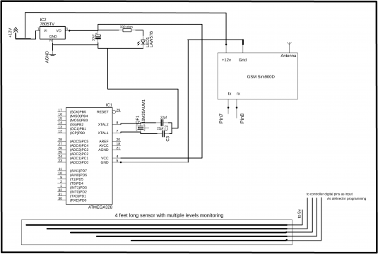
In the circuit diagram, you can see LM7805 voltage regulator is used. As the atmega328 controller needs regulated 5v. The advantage of using the regulator is that if the voltage at the input fluctuates the regulator will still keep the voltage at 5v. A 2.5v led is connected through a 330-ohm resistor. This value is calculated using the ohm law
V = IR
V = 5V
Led current = 20ma
So, R = ( 5 – 2.5 ) / 20ma = 125 ohm
The nearest value available is 330 ohm. This value can be easily found in any electronic shop. We always select a value that can be easily found in the market.
The GSM module is given 12v, it has a built-in 12v regulator so it doesn’t need a regulator. The Sensor used is simply consisting of the steel rods. One rod is connected with the 5v and the other roads are connected with the microcontroller inputs. So when water comes in connection with the rods the specified level can be found. The sensor’s physical construction will be shown in the sensor designing section.
COST ANALYSIS:
GSM MODULE: 6000 RS
ARDUINO UNO: 800
ULTRASONIC SENSOR : 600
total = 6000 + 800 + 600 = 7400Rs.
Now my designed controller board and sensor
Atmega328 = 70rs
Crystals = 10rs
Regulator = 10rs
Led = 1rs
Sensor = 200
GSM module = 6000rs
total = 70 + 10 + 10 + 1 + 200 + 6000 = 6290
and additional charge including the electricity and other charges.
6290 + 10 = 6300
Difference
7400 – 6290 = 1110Rs.
Just in one Monitoring station, we can save up to 1110Rs, which is such a great amount.
Now in terms of maintenance if we look at the Arduino that’s designed in such a way that it takes a lot of time in checking and troubleshooting. While my designed circuit can be fixed in mints and can be locally handled by any technician
Flood Monitoring System Proteus Simulation:

The Proteus simulation really helped me in testing my final Controller programming.
Download: Flood monitoring system simulation proteus
Flood Monitoring System PCB:

This PCB is designed in the Cadsoft Eagle 9.1.0 version. If you want to learn the basics about the schematic making and PCB designing then watch the video tutorial:
Board size: 2.7in by 2in
It was manually routed to best suit the PCB as desired. After making the PCB I printed the design on a glossy paper using a laserjet printer. Then with the help of the iron, I transferred the design on the copper plate. Then I prepared the ferric chloride acid solution to etch the PCB plate. Then after this, I drilled the PCB and installed the components.
I kept the PCB size small enough to reduce the cost per unit. Because the size of the PCB will have a major effect on the enclosure design, small PCB will result in a small enclosure while the larger PCB will result in a big enclosure. The larger enclosure will need more material, more injection pressure, more clamping force, and a big machine. Because when it comes to the Plastic Injection machines, the sizes of the machines varies as per the injection pressure and clamping force. These things will be discussed in detail when I will be making the plastic enclosure.
Testing and Troubleshooting:
After I completed the soldering job, before powering up the controller board, first I checked all the pins of the microcontroller whether they are short or not. Then I checked the voltage at the output of the regulator. During the testing, I found 2 pins short which I fixed using the solder sucker to suck the excess solder. Then it was ready for the interfacing.
Receiver Side Plastic enclosure designing
Before we start the enclosure designing, we should know exactly, what are the dimensions of the circuits and the locations of the ports? The type of GSM module I am using can be fixed on the top of the Arduino Uno, which will reduce the size of the plastic enclosure.
For the exact dimensions to be measured, first of all, I designed the Arduino Uno and GSM module in the SolidWorks and then with the help of the dimensions tool I found the width and height of the combined modules. The recorded dimensions are as follows.
Width = 81mm
Height = 29mm
First, I defined the walls with thickness as 2mm.
So the resulting dimensions after the enclosure is designed is
Width = 83
Height = 32
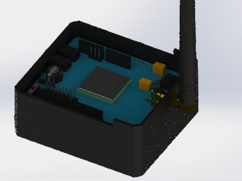
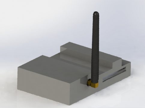
Final, enclosure picture in perspective view.

The Square hole is for the USB cable.
The large circular hole is for the GSM antenna.
A small hole is for the dc power jack.
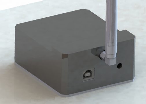
Back view

The backside two holes are for the MIC and headphone. Because this GSM module is a GPRS type. We can make calls as well. The overall wall thickness of this enclosure is 2mm. 2mm is the most common thickness used for plastic parts.
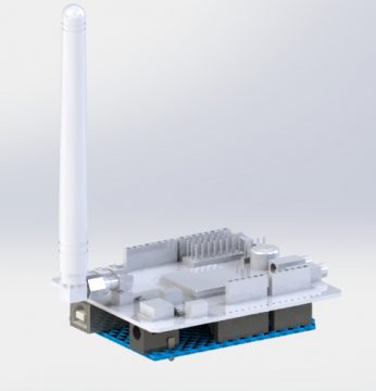
The GSM, Arduino, and Enclosure all together:

As you can see in the picture the final receiver will need a small area. It’s in a compact form and can be placed anywhere on the table. This design is now portable it can be shifted to any area even the person can take it home and can connect it with the laptop to monitor.
Enclosure Analysis:
- First, we will check whether the designed Enclosure can be manufactured if it has the defects how it can be fixed?
We will do the analysis in SolidWorks using Mold tools. So I started with the drafted analysis.

The green color shows the positive draft which is fine.
The walls having yellow color means that it needs a draft. Right now these walls are at 90 degrees which will result in maximum friction with the wall of the Aluminum mold. When the Plastic injection process is completed and we remove the part from the mold then it becomes hard to take out the part from the mold. So that’s why now we will change the draft angle so that the friction with the wall can be minimized. in most common practice a draft angle of 1 to 3 degree is used in small parts. In my case, I will apply a 2-degree draft.

Now it’s ready for the manufacturing process because this part can be easily ejected from the Aluminum Mold. As we can clearly see in the picture below, the walls are no more at 90 degrees. Now the walls have the draft.

Now we will select the type of material that we will be using.
For this enclosure, I decided to use ABS. This material can be easily found in Pakistan and other countries around the world. In Pakistan, this material costs 150Rs per Kg.
Mass properties
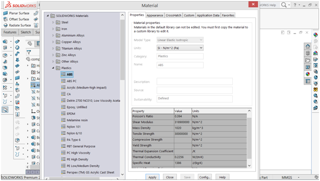
So now that the part is ready for manufacturing, the type of the material is also has been selected. Now we will start the Plastic analysis. For this purpose, we will be using Plastic analysis tools. In this analysis, we will find all the important parameters.
first, we select the polymer
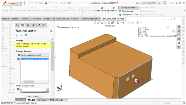
Now the injection location will be selected, and the nozzle size will be specified. Through this injection location, the part will be filled with plastic. I selected the backside of the part and the nozzle size 4mm.
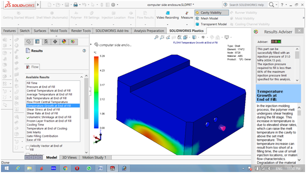
This is the final step before the Actual analysis will be started. In this step, we will be entering the temperature, the Mold temperature, injection pressure limit in Mpa. In this simulation, I am deciding to use the 100Mpa which is equal to 14503.8 PSI. It means the machine is capable of producing 14503.8 PSI. Now we will check whether our part can be designed using such machine or not? If we were able to make this part within these limits it means our design is safe.
Fill time
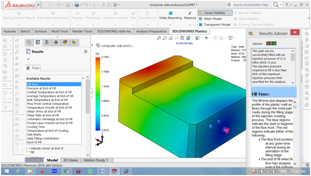
As you can see clearly the fill time for this part is 2.1952 Seconds.
This part can be successfully filled with an injection pressure of 31.0 MPa (4504.15 psi).
The injection pressure required to fill is less than 66% of the maximum injection pressure limit specified for this analysis, which means you are well under your specified limit.
You may be able to reduce the part thickness and decrease cooling time, but be sure to run an additional analysis after changing the thickness to ensure your part will still fill within the specified injection pressure limit.
Since the Maximum Temperature at End of Fill has remained within 10 deg C of the starting melt temperature, there is little to no risk of plastics material degradation.
The predicted cooling time is determined when 90% of the part temperature is less than the material ejection temperature.
From the injection pressure, we know that this part can be made even on smaller injection molding machines.
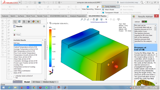
The pressure at the end of the fill
The central temperature at the end of fill

The average temperature at the end of fill

Temperature growth at the end of the fill
the sheer rate at the end of the fill

The small bubble at the top of the part shows the location where the air is trapped. So the Mold should be provided with the air vents for the air escape. If the air vents are not used then the final part will not look good.
cooling time

The cooling is about 24 seconds. It means that after the injection process we will have to wait for 24 seconds before we can remove the part from the mold. If we want to reduce the cooling time then the best choice is to use the water tubing in the mold to quickly cold the part.
Gate filling contribution

This part can be successfully filled with only one injection location.
Cost calculation per unit
In SolidWorks, we can easily find the mass of the part that we have designed. From the mass properties, we can find the grams and then we can know for per 1kg how many parts we can make, and then adding the electricity and labor cost we can estimate the final price of the unit. Look at the below picture.

You can see that the part weighs around 37.03 grams
With 1kg material, we can make 27 units.
As we know 1kg = 1000 grams
1000 / 37 = 27.0052 = 27 units.
The type of material we are using has a price of 150Rs per kg.
so the per-unit price will be
150 / 27 = 5.6 Rs.
Now as rule of thumb we can add 10rs more for the electricity, labor cost and other things.
5.6 + 10 = 15.6
So the final price will be 15.6Rs for this enclosure.
Water level monitoring side enclosure
Now you can run the same analysis for the receiver side Plastic enclosure.

Mass properties

as we know the per kg cost of the material is 150rs
150 / 21 = 7.14Rs
Adding other expenses. 7.14 + 10 = 17rs.
so the final price of this unit will 17rs.
Final cost Analysis
15.6Rs was the price of the first enclosure and 17Rs is the price of the other unit.
so both the enclosure can be manufactured at the cost of 15.6 + 17 =32.6 Rs.
from the business point of view which is the lowest price. In the market both the enclosure can be sold at a price more than 200Rs or even more. So the profit margin rate is high.
Machine size
As the injection pressure needed for the last part was high which was about 8163 PSI. So we will go for the machine with injection pressure approximately 9000 PSI. We are selecting high PSI as there can be some friction losses. The pressure tank should be capable of producing 9000 PSI. To keep the cost of the machine lower I will suggest a semi-automatic injection molding machine, consisting of only two pneumatic cylinders that can be operated with compressed air. The desired pneumatic cylinders and pressure tanks can be arranged by the dealers if they are given these values.
The 9000 PSI machine price as searched on the internet is
Clamping Force (Toggle), 9000 PSI Max. Injection Pressure, 0-800 F, 120 VAC, $3,200.00.
” on eBay”
For the company to start we will need at least 4 rooms.
1 room for the machine.
1 room for the raw material.
1 room as an office
1 room for the circuits making and assembling.
Flood Monitoring System Water level Sensor:
Due to errors in Ultrasonic sensors, needs complicated programming, wastes the microcontroller processing time and moreover needs maintenance. It can generate false signals when anything comes in front of the sensor. I did a lot of research on this sensor and later decided to make my own Sensor that will generate no false signals, will need no maintenance, needs no complicated programming and can be easily connected with the microcontroller by anyone. The Sensor I am designing will be kept inside the 1inch diameter perforated pipe so that the water can enter into the pipe. Sensor construction can be easily seen in the picture below.
Dimensions of the water level monitoring sensor.
4 feet long.
1-inch diameter PVC pipe.
Consisting of 7 copper wires.

Sensor inside setup

You can see clearly all the wires are insulated from each other. The working principle is so easy. When the water comes in contact with the lowest wire and with any other wire above it will represent that level. Each wire represents a level. So, when the water level will increase above the normal level, the controller will send a message to the control room with the help of the GSM Module.
Flood Monitoring System Arduino Programming:
In this Flood Monitoring System, two programs are used, one program is written for the Transmitter side and the other program is written for the receiver side.
Flood Monitoring System Transmitter side Programming:
The Ultrasonic Sensor based program is more famous, so that’s why the following program is about the Ultrasonic Sensor.
|
1 2 3 4 5 6 7 8 9 10 11 12 13 14 15 16 17 18 19 20 21 22 23 24 25 26 27 28 29 30 31 32 33 34 35 36 37 38 39 40 41 42 43 44 45 46 47 48 49 50 51 52 53 54 55 56 57 58 59 60 61 62 63 64 65 66 67 68 69 70 71 72 73 74 75 76 77 78 79 80 81 82 83 84 85 86 87 88 89 90 91 92 93 94 95 96 97 98 99 100 101 102 103 104 105 106 107 108 109 110 111 112 113 114 115 116 117 118 119 120 121 122 123 124 125 126 127 128 129 130 131 132 133 134 135 136 137 138 139 140 141 142 143 144 145 146 147 148 149 150 151 152 153 154 155 156 157 158 159 160 161 162 163 164 165 166 167 168 169 170 171 172 173 174 |
#include <SoftwareSerial.h> SoftwareSerial SIM900(7, 8); // gsm module connected here #define trigpin 4 // digital pin 4 #define echopin 2 // digital pin 2 String textForSMS; // flags definitions to stop the repetitions of sms int flag1 = 0; // int flag2 = 0; // int flag3 = 0; // int flag4 = 0; // void setup() { Serial.begin(9600); SIM900.begin(19200); SIM900power(); delay(5000); // give time to log on to network. Serial.println(" logging time completed!"); randomSeed(analogRead(0)); pinMode(trigpin, OUTPUT); pinMode(echopin, INPUT); } void SIM900power() // software equivalent of pressing the GSM shield "power" button { digitalWrite(9, HIGH); delay(1000); digitalWrite(9, LOW); delay(7000); } void sendSMS(String message) { SIM900.print("AT+CMGF=1\r"); // AT command to send SMS message delay(100); SIM900.println("AT + CMGS = \"+923049844408\""); // recipient's mobile number, in international format delay(100); SIM900.println(message); // message to send delay(100); SIM900.println((char)26); // End AT command with a ^Z, ASCII code 26 delay(100); SIM900.println(); delay(5000); // give module time to send SMS // SIM900power(); // turn off module } void loop() { int duration, distance; digitalWrite(trigpin, HIGH); delayMicroseconds(1000); digitalWrite(trigpin, LOW); duration = pulseIn(echopin,HIGH); distance = ( duration / 2) / 29.1; Serial.println(distance); delay(100); if ( (distance > 0 ) && (distance <10 ) && ( flag1 == 0)) { Serial.println (" critical2 "); textForSMS = "critical situation 2 "; sendSMS(textForSMS); Serial.println("message sent."); delay(10000); flag1 = 1; delay(1000); } if ( (distance > 10 ) && (distance <20 ) && ( flag1 == 1)) { Serial.println (" critical1 "); textForSMS = "critical situation 1 "; sendSMS(textForSMS); Serial.println("message sent."); delay(10000); flag1 = 0; delay(1000); } if ( (distance > 20 ) && (distance <30 ) && ( flag2 == 0)) { Serial.println ("level high2 "); textForSMS = "level high2 "; sendSMS(textForSMS); Serial.println("message sent."); delay(10000); flag2 = 1; delay(1000); } if ( (distance > 30 ) && (distance <40 )&& (flag2 == 1)) { Serial.println ("level high1 "); textForSMS = "level high1 "; sendSMS(textForSMS); Serial.println("message sent."); delay(10000); flag2 = 0; delay(1000); } if ( (distance > 40 ) && (distance <50 ) && ( flag3 == 0)) { Serial.println ("level medium 2 "); textForSMS = "medium level 2 "; sendSMS(textForSMS); Serial.println("message sent."); delay(10000); flag3 = 1; delay(1000); } if ( (distance > 50 ) && (distance <60 )&& (flag3 == 1)) { Serial.println ("medium level 1 "); textForSMS = "medium level 1 "; sendSMS(textForSMS); Serial.println("message sent."); delay(10000); flag3 = 0; delay(1000); } if ( (distance > 60 ) && (distance <70 ) && ( flag4 == 0)) { Serial.println ("Normal level "); textForSMS = "normal level "; sendSMS(textForSMS); Serial.println("message sent."); delay(10000); flag4 = 1; delay(1000); } if ( (distance > 70 ) && (distance <100 )&& (flag4 == 1)) { Serial.println ("lower "); textForSMS = "lower "; sendSMS(textForSMS); Serial.println("message sent."); delay(10000); flag4 = 0; delay(1000); } //Serial.print(distance); //Serial.print("Centimeters\n"); //delay(2000); } |
Flood Monitoring System Receiver Side Programming:
|
1 2 3 4 5 6 7 8 9 10 11 12 13 14 15 16 17 18 19 20 21 22 23 24 25 26 27 28 29 30 31 32 33 34 35 36 37 38 |
#include <SoftwareSerial.h> char inchar; // Will hold the incoming character from the GSM shield SoftwareSerial SIM900(7, 8); String data; void setup() { Serial.begin(9600); SIM900.begin(19200); delay(10000); // give time to log on to network. SIM900.print("AT+CMGF=1\r"); // set SMS mode to text delay(100); SIM900.print("AT+CNMI=2,2,0,0,0\r"); // blurt out contents of new SMS upon receipt to the GSM shield's serial out delay(100); SIM900.println("AT+CMGD=1,4"); // delete all SMS delay(5000); Serial.println("Ready..."); } void loop() { //If a character comes in from the cellular module... if(SIM900.available() >0) { inchar=SIM900.read(); Serial.print(inchar); } } |
Flood Monitoring System Computer Application Programming:
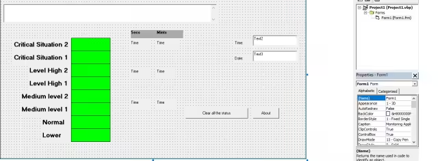
This is how the application form looks like. This application was designed in visual basic 6.0. But you can also design the same application using VB.net. I have so many tutorials on desktop application designing using VB.net. which are available on this website and also on my YouTube cannel “Electronic Clinic”.
|
1 2 3 4 5 6 7 8 9 10 11 12 13 14 15 16 17 18 19 20 21 22 23 24 25 26 27 28 29 30 31 32 33 34 35 36 37 38 39 40 41 42 43 44 45 46 47 48 49 50 51 52 53 54 55 56 57 58 59 60 61 62 63 64 65 66 67 68 69 70 71 72 73 74 75 76 77 78 79 80 81 82 83 84 85 86 87 88 89 90 91 92 93 94 95 96 97 98 99 100 101 102 103 104 105 106 107 108 109 110 111 112 113 114 115 116 117 118 119 120 121 122 123 124 125 126 127 128 129 130 131 132 133 134 135 136 137 138 139 140 141 142 143 144 145 146 147 148 149 150 151 152 153 154 155 156 157 158 159 160 161 162 163 164 165 166 167 168 169 170 171 172 173 174 175 176 177 178 179 180 181 182 183 184 185 186 187 188 189 190 191 192 193 194 195 196 197 198 199 200 201 202 203 204 205 206 207 208 209 210 211 212 213 214 215 216 217 218 219 220 221 222 223 224 225 226 227 228 229 230 231 232 233 234 235 236 237 238 239 240 241 242 243 244 245 246 247 248 249 250 251 252 253 254 255 256 257 258 259 260 261 262 263 264 265 266 267 268 269 270 271 272 273 274 275 276 277 |
Option Explicit Dim BUFFERS$ Private Declare Sub Sleep Lib "kernel32" (ByVal dwMilliseconds As Long) Dim message As Integer Dim search As String Dim gsmsearch As String Dim mints As Integer Dim mints2 As Integer Dim mints3 As Integer Dim seconds As Integer Dim seconds2 As Integer Dim seconds3 As Integer Dim i As Integer Dim counter1 As Integer Dim mytext As String Private Sub Check6_Click() mytext = Text1.Text Open "c:\myfile.txt" For Append As #1 Write #1, mytext Close #1 End Sub Private Sub Command1_Click() frmAbout.Show End Sub Private Sub Command2_Click() Shape1.FillColor = &HFF00& Shape2.FillColor = &HFF00& Shape3.FillColor = &HFF00& Timer2.Enabled = False Timer6.Enabled = False Timer7.Enabled = False mints = 0 mints2 = 0 mints3 = 0 seconds = 0 seconds2 = 0 seconds3 = 0 End Sub Private Sub Form_Load() With MSComm2 ' gsm connected here .CommPort = 5 .Settings = "9600,N,8,1" .Handshaking = comRTS .RTSEnable = True .DTREnable = True .RThreshold = 1 .SThreshold = 1 .InputMode = comInputModeText .InputLen = 0 .PortOpen = True 'must be the last End With counter1 = 1 Timer8.Enabled = False End Sub Private Sub Timer1_Timer() 'txtrec.Text = "" txtrec.Text = txtrec.Text + MSComm2.Input Label2.Caption = txtrec.Text search = txtrec.Text If InStr(search, "critical situation 2") Then Timer8.Enabled = True shpcs2.FillColor = &HFF& shpcs1.FillColor = &HFF& shplh2.FillColor = &HFF& shplh1.FillColor = &HFF& shpml2.FillColor = &HFF& shpml1.FillColor = &HFF& shpn.FillColor = &HFF& shpl.FillColor = &HFF& txtrec.Text = "" Timer2.Enabled = True ElseIf InStr(search, "critical situation 1") Then Timer8.Enabled = True shpcs2.FillColor = &HFF00& ' green color shpcs1.FillColor = &HFF& ' red color shplh2.FillColor = &HFF& shplh1.FillColor = &HFF& shpml2.FillColor = &HFF& shpml1.FillColor = &HFF& shpn.FillColor = &HFF& shpl.FillColor = &HFF& txtrec.Text = "" Timer6.Enabled = True ElseIf InStr(search, "level high2") Then Timer8.Enabled = True shpcs1.FillColor = &HFF00& ' green shpcs2.FillColor = &HFF00& ' green color shplh2.FillColor = &HFF& shplh1.FillColor = &HFF& shpml2.FillColor = &HFF& shpml1.FillColor = &HFF& shpn.FillColor = &HFF& shpl.FillColor = &HFF& txtrec.Text = "" Timer7.Enabled = True ElseIf InStr(search, "level high1") Then Timer8.Enabled = True shpcs1.FillColor = &HFF00& ' green shpcs2.FillColor = &HFF00& ' green color shplh2.FillColor = &HFF00& ' green color shplh1.FillColor = &HFF& ' red shpml2.FillColor = &HFF& shpml1.FillColor = &HFF& shpn.FillColor = &HFF& shpl.FillColor = &HFF& txtrec.Text = "" ElseIf InStr(search, "medium level 2") Then Timer8.Enabled = True shpcs1.FillColor = &HFF00& ' green color shpcs2.FillColor = &HFF00& ' green color shplh2.FillColor = &HFF00& ' green color shplh1.FillColor = &HFF00& ' green color shpml2.FillColor = &HFF& ' red shpml1.FillColor = &HFF& shpn.FillColor = &HFF& shpl.FillColor = &HFF& txtrec.Text = "" ElseIf InStr(search, "medium level 1") Then Timer8.Enabled = True shpcs1.FillColor = &HFF00& ' green color shpcs2.FillColor = &HFF00& ' green color shplh2.FillColor = &HFF00& ' green color shplh1.FillColor = &HFF00& ' green color shpml2.FillColor = &HFF00& ' green color shpml1.FillColor = &HFF& ' red color shpn.FillColor = &HFF& shpl.FillColor = &HFF& txtrec.Text = "" ElseIf InStr(search, "normal level") Then Timer8.Enabled = True shpcs1.FillColor = &HFF00& ' green color shpcs2.FillColor = &HFF00& ' green color shplh2.FillColor = &HFF00& ' green color shplh1.FillColor = &HFF00& ' green color shpml2.FillColor = &HFF00& ' green color shpml1.FillColor = &HFF00& ' green color shpn.FillColor = &HFF& ' red color shpl.FillColor = &HFF& txtrec.Text = "" ElseIf InStr(search, "lower") Then Timer8.Enabled = True shpcs1.FillColor = &HFF00& ' green color shpcs2.FillColor = &HFF00& ' green color shplh2.FillColor = &HFF00& ' green color shplh1.FillColor = &HFF00& ' green color shpml2.FillColor = &HFF00& ' green color shpml1.FillColor = &HFF00& ' green color shpn.FillColor = &HFF00& ' green color shpl.FillColor = &HFF& ' red color txtrec.Text = "" End If 'Sleep (1000) End Sub Private Sub Timer2_Timer() seconds = seconds + 1 Label9.Caption = seconds If seconds = 59 Then seconds = 0 mints = mints + 1 Label10.Caption = mints End If End Sub Private Sub Timer4_Timer() Text2.Text = Time Text3.Text = Date End Sub Private Sub Timer6_Timer() seconds2 = seconds2 + 1 Label11.Caption = seconds2 If seconds2 = 59 Then seconds = 0 mints2 = mints2 + 1 Label12.Caption = mints2 End If End Sub Private Sub Timer7_Timer() seconds3 = seconds3 + 1 Label13.Caption = seconds3 If seconds3 = 59 Then seconds3 = 0 mints3 = mints3 + 1 Label14.Caption = mints3 End If End Sub |
Discover more from Electronic Clinic
Subscribe to get the latest posts sent to your email.


Hello i am student from the Philippines and I want to do a research about flood monitoring system as well, since the Philippines have always been struck by around 20 typhoons per year. I wanted to design a much easier but effective flooding system and since I’m still a student i hope to make an alarm system which is less costly as much as possible but still effective. I want to ask or consult you about this, i hope that this reaches you and once you do please email me at marcy.boral09@gmail.com. thank you so much!
Hi, I am a student from the Philippines, taking Mechanical Engineering and as part of the fulfillment of the subject Basic Electronics Engineering. We have given a task for our final project to create device related to Microcontroller or Arduino. We have been suggested to create a monitoring system, a Environmental Monitoring System in which this can monitor Light, Humidity, Temperature and Soil Moisture integrated with IoT (Blynk) and GSM SIM900A module using ESP32. I have already achieve how to integrate the sensors with Blynk app. The only problem i am having is with the GSM SIM900A, seems like i can’t get it to function– Call/Message. I have read some of you blog but i can’t still find my way to attain such steps. i hope this reaches you. hoping you can help me. I am looking forward to talk with you, please email me at anignatop321@gmail.com. Thank you so much!