How to Track my Car Location using Arduino, GPS, & GSM, Locate my Car
Table of Contents
How to Track my Car Location using Arduino:
How to Track my Car Location- In this article, I am going to track my Car location using Arduino, Neo 6M GPS Module, and the GSM SIM900A Module. I have also added some other cool features, which I will practically test in a minute.
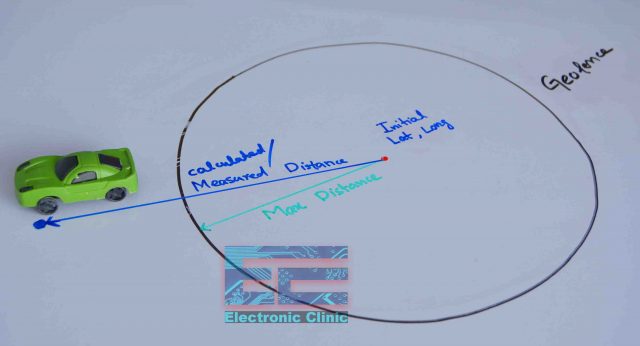
In my previous project, I implemented Geofencing technology in an attempt to reinforce my car security. As I have elaborated in my previous article, you can define a virtual boundary around any area with the help of Geofencing by means of using GPS coordinates.
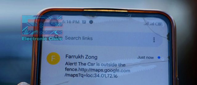
In a similar fashion, I built up a virtual fence for my car so that whenever my car happened to go out of that prescribed area, I received an alert message on my cell phone which prompted me that “the car is outside the fence”.
Geofencing technology can be applied in order to track any sort of thing. It can indicate when does a car or any other vehicle or thing enters that particular area or leaves it. So if you are interested too to implement and take advantage of the all-important Geofencing technology, you must inevitably read my previous article. Anyhow, let us move toward our original topic “how to track my car location”
Nowadays, the ratio of car stealing has enhanced to a shocking extent throughout the world. If a car has been stolen and no tracker was fixed on it, it virtually becomes impossible to locate that car. You can do nothing about your stolen car, except that you have extraordinary level contacts and try and track your car through its number by means of checking each and every CCTV footage. However, it is hard for everyone to have access to these high-level contacts and utilize such a procedure in order to locate a pilfered car.
So, if we are not lucky enough to have contacts or huge approaches, then it is compulsory that we purchase or otherwise manufacture some type of a GPS tracking system, so as to track our car. As an engineer, I shall prefer, that I design a customized GPS tracking system for my car, where I may add some extra features according to my choice and needs.
Here, is a prototype model of my Arduino-based GPS tracking system, the finalization work of which, is still in progress. When all the testing tasks have been finished, then I will design a PCB and an enclosure for it. Anyways, the features which I have added until now, include:
Features:
- Tracking a car location, however without any need for recourse to an internet service or any type of online dashboard. We can just find out the location of our car with the help of a cell phone. We have to send just an SMS from our cell phone and the tracking system will send us the Car’s GPS coordinates along with the Google’s map URL link. And then with the help of Google Map, we can track the exact location of our car. This is really an amazing feature, through which you can learn about the precise location of your car at any moment.
- I have also added a feature of speed monitoring into it. Mostly, my brothers drive the car and I do not want them to indulge in over-speeding. So, whenever they cross a certain speed limit, a buzzer will beep loudly in the car. It will keep honking until the car speed has been reduced to the desired limits.
If you want, that along with a buzzer, a message may also be passed on to the near and dears one back at home, you have to modify my program slightly, which can be done quite easily. When you study the code, you will have an idea of where the modification is going to be desired.
- The third feature is an extremely important one, which is accident monitoring. During accidents, people do not often have that much time to resort to their cell phones in order to get family members informed about the incident. Therefore, I have added this button for demonstration purposes. As soon as this button is pressed, an accident alert message will be delivered to family members who will also have GPS coordinates of the accident location. You can employ such buttons or limit switches or sensors anywhere on your car’s front, back, or along its sides. You have to do just a little adjustment in the program.
I think we have discussed the topic fairly well, now let’s practically check this system.
Altium Designer & Altium 365:
Altium 365 lets you hold the fastest design reviews ever. Share your designs from anywhere and with anyone with a single click. it’s easy, leave a comment tagging your teammate and they’ll instantly receive an email with a link to the design. Anyone you invite can open the design using a web browser. Using the browser interface, you’re able to comment, markup, cross probe, inspect, and more. Comments are attached directly to the project, making them viewable within Altium designer as well as through the browser interface. Design, share, and manufacture, all in the same space with nothing extra to install or configure. Connect to the platform directly from Altium Designer without changing how you already design electronics. Altium 365 requires no additional licenses and comes included with your subscription plan. Start with Altium Designer and Activate Altium 365.
Practical Testing:
For the demonstration purposes, my brother is going to steal the car and after reaching a certain location, he will stop it. I have no idea about that location and so I will have to find out my car’s location with the help of my Arduino-based tracking system and smartphone. So let’s do it.
Twenty minutes have passed since my brother has driven away the car. Now, I am going to find the car’s location. I have done its programming in such a way that if I send a blank message or write any character in the message, the tracking system will respond in both situations.
I have received a reply from my tracking system. You can see there is a Google map URL link. I can determine the exact location of my car by clicking on this link.
I guide you along with my phone’s screen towards that location, so that you may understand and see everything by yourself. Here are the GPS coordinates of my car’s location. Now if I click on start, Google Map will show me the approximate time as well as indicate the approximate direction.
So let us move on a bike towards the location. It took me around 3 minutes to get to my Car’s location.
And here it is my car which we have located with the help of an Arduino-based GPS tracking system.
As I have mentioned in the beginning, I have also introduced an accident location tracking feature in this system, it also works similarly. The only difference is that in case of an accident, it sends a message automatically. I have fixed a button on the front bumper of my car. As soon as it is pressed, I immediately receive an accident alert message.
Now let us check our speed monitoring feature. For this purpose, I am about to sit in my car and practically see what happens when the car speed exceeds the speed limit, whether the buzzer turns ON or not. I set the maximum speed limit of 50 Km/h. When the car speed exceeded 50km/h the buzzer was activated, you can practically watch this in the video which is given at the end of this article.
So far, my designed GPS car tracking system has done everything perfectly and I also feel delighted about it, in the future, I am planning to add some extra features to it. That’s when somebody tries to open a car’s door or its bonnet, I receive a message on my cell phone or maybe some other feature, you can also tell me in a comment, which features I need to add. Now, you have got an idea of what exactly you are going to learn after watching this video. So, without any further delay, let’s get started!!!
Amazon Links:
Arduino Nano USB-C Type (Recommended)
Other Tools and Components:
ESP32 WiFi + Bluetooth Module (Recommended)
Super Starter kit for Beginners
PCB small portable drill machines
*Please Note: These are affiliate links. I may make a commission if you buy the components through these links. I would appreciate your support in this way!
Arduino Neo 6M GPS module issue!
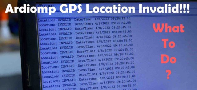
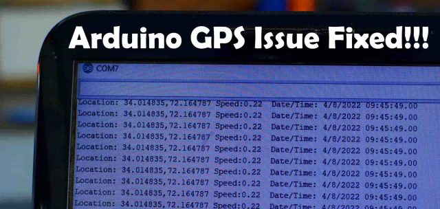
You don’t have to be worried if you see something like this on your Arduino Serial monitor. Sometimes GPS module takes several minutes to connect with the Satellites. When using a GPS module, make sure you are not inside a big building, basement, etc. Try, find an open space. Sometimes GPS module even takes 30 minutes. If you can see the date and time then it’s a good signal that your GPS module has no issues. The same thing happened to me too. Anyways, I waited and then my GPS module started giving me the exact latitude and longitude values.
GSM and GPS interfacing with Arduino:
All the electronics are powered up using a 5Volts regulated power supply, make sure the power supply is around 2A. The RXD and TXD pins of the GSM Sim900A module are connected with the Arduino pins D8 and D7. The RXD and TXD pins of the Neo 6M GPS Module are connected with the Arduino pins D10 and D9 respectively. A pushbutton is connected with the Arduino Pin D12.
Car location Tracking Arduino Programming:
|
1 2 3 4 5 6 7 8 9 10 11 12 13 14 15 16 17 18 19 20 21 22 23 24 25 26 27 28 29 30 31 32 33 34 35 36 37 38 39 40 41 42 43 44 45 46 47 48 49 50 51 52 53 54 55 56 57 58 59 60 61 62 63 64 65 66 67 68 69 70 71 72 73 74 75 76 77 78 79 80 81 82 83 84 85 86 87 88 89 90 91 92 93 94 95 96 97 98 99 100 101 102 103 104 105 106 107 108 109 110 111 112 113 114 115 116 117 118 119 120 121 122 123 124 125 126 127 128 129 130 131 132 133 134 135 136 137 138 139 140 141 142 143 144 145 146 147 148 149 150 151 152 153 154 155 156 157 158 159 160 161 162 163 164 165 166 167 168 169 170 171 172 173 174 175 176 177 178 179 180 181 182 183 184 185 186 187 188 189 190 191 192 193 194 195 196 197 198 199 200 201 202 203 204 205 206 207 208 209 210 211 212 213 214 215 216 217 218 219 220 221 222 223 224 225 226 227 228 |
// Car Location Tracking using Arduino, GSM SIM900A, and Neo 6M GPS Module // electroniclinic.com #include <SoftwareSerial.h> #include <stdlib.h> #include <TinyGPS++.h> static const int RXPin = 9, TXPin = 10; static const uint32_t GPSBaud = 9600; // The TinyGPS++ object TinyGPSPlus gps; // The serial connection to the GPS device SoftwareSerial ss(RXPin, TXPin); // for gps SoftwareSerial SIM900(7, 8); // for gsm module int A_Sensor = 12; // accident monitoring sensor, pushbutton or you can use any other digital sensor int Buzzer = 5; // Buzzer is connected with pin 5 of the Arduino char inchar; // Will hold the incoming character from the GSM shield String textForSMS; // stores the alert message double longitude; // stores the longitude value double latitude; // stores the Latitude value char buff[10]; String mylong = ""; // for storing the longittude value String mylati = ""; // for storing the latitude value int gpsflag = 0; int mycounter = 0; void setup() { SIM900.begin(19200); Serial.begin(9600); ss.begin(GPSBaud); delay(5000); // give time to log on to network. Serial.println(" logging time completed!"); randomSeed(analogRead(0)); pinMode(A_Sensor, INPUT_PULLUP); pinMode(Buzzer, OUTPUT); } void sendSMS(String message) { SIM900.print("AT+CMGF=1\r"); // AT command to send SMS message delay(100); SIM900.println("AT + CMGS = \"+923339537499\""); // recipient's mobile number, in international format delay(100); SIM900.println(message); // message to send delay(100); SIM900.println((char)26); // End AT command with a ^Z, ASCII code 26 delay(100); SIM900.println(); delay(5000); // give module time to send SMS } void loop() { // This sketch displays information every time a new sentence is correctly encoded. while (ss.available() > 0) if ((gps.encode(ss.read())) && (gpsflag == 0)) { displayInfo(); gpsflag = 1; } if (millis() > 5000 && gps.charsProcessed() < 10) { Serial.println(F("No GPS detected: check wiring.")); while(true); } // for the A_Sensor //***************************************************************** //**************************************************************** if(digitalRead(A_Sensor) == LOW) { displayInfo(); latitude = gps.location.lat(), 6 ; longitude = gps.location.lng(), 6 ; // for latitude mylati = dtostrf(latitude, 3, 6, buff); mylong = dtostrf(longitude, 3, 6, buff); //textForSMS = textForSMS + "Latitude:" + "," + mylati + "," + "Longitude: "+ mylong + ","; textForSMS = "Accident:\n "; textForSMS = textForSMS + "http://www.google.com/maps/place/" + mylati + "," + mylong ; sendSMS(textForSMS); textForSMS = ""; Serial.println(textForSMS); Serial.println("message sent."); delay(2000); } displayInfo(); if (gps.speed.kmph() > 50 ) { digitalWrite(Buzzer, HIGH); } if (gps.speed.kmph() < 50 ) { digitalWrite(Buzzer, LOW); } mycounter = mycounter + 1; if ( (mycounter > 50) && ( mycounter < 100)) { gpsflag = 0; ss.begin(GPSBaud); } if ( mycounter > 100 ) mycounter = 0; if(gpsflag == 1) { SIM900.begin(19200); // we again activate the serial communication. if(SIM900.available() > 0) { Serial.println("message received:"); inchar=SIM900.read(); Serial.println(inchar); displayInfo(); latitude = gps.location.lat(), 6 ; longitude = gps.location.lng(), 6 ; mylati = dtostrf(latitude, 3, 6, buff); mylong = dtostrf(longitude, 3, 6, buff); textForSMS = textForSMS + "http://www.google.com/maps/place/" + mylati + "," + mylong ; sendSMS(textForSMS); textForSMS = ""; Serial.println(textForSMS); Serial.println("message sent."); inchar = 'z'; // garbage value delay(2000); gpsflag = 0; ss.begin(GPSBaud); // we again activate the gps module, so now gps will work and gsm will not.. delay(100); } } } void displayInfo() { Serial.print(F("Location: ")); if (gps.location.isValid()) { Serial.print(gps.location.lat(), 6); Serial.print(F(",")); Serial.print(gps.location.lng(), 6); Serial.print(" "); Serial.print(F("Speed:")); Serial.print(gps.speed.kmph()); } else { Serial.print(F("INVALID")); } Serial.print(F(" Date/Time: ")); if (gps.date.isValid()) { Serial.print(gps.date.month()); Serial.print(F("/")); Serial.print(gps.date.day()); Serial.print(F("/")); Serial.print(gps.date.year()); } else { Serial.print(F("INVALID")); } Serial.print(F(" ")); if (gps.time.isValid()) { if (gps.time.hour() < 10) Serial.print(F("0")); Serial.print(gps.time.hour()); Serial.print(F(":")); if (gps.time.minute() < 10) Serial.print(F("0")); Serial.print(gps.time.minute()); Serial.print(F(":")); if (gps.time.second() < 10) Serial.print(F("0")); Serial.print(gps.time.second()); Serial.print(F(".")); if (gps.time.centisecond() < 10) Serial.print(F("0")); Serial.print(gps.time.centisecond()); } else { Serial.print(F("INVALID")); } Serial.println(); } |
Code explanation:
These are the same libraries I have been using in all of my GPS based projects.
|
1 2 3 4 5 |
#include <SoftwareSerial.h> #include <stdlib.h> #include <TinyGPS++.h> |
Next, I defined pins for the GPS and GSM modules.
|
1 2 3 4 5 6 7 8 9 10 11 12 13 14 15 16 17 |
static const int RXPin = 9, TXPin = 10; static const uint32_t GPSBaud = 9600; // The TinyGPS++ object TinyGPSPlus gps; // The serial connection to the GPS device SoftwareSerial ss(RXPin, TXPin); // for gps SoftwareSerial SIM900(7, 8); // for gsm module |
I also defined a pin to which a pushbutton is connected.
|
1 |
int A_Sensor = 12; |
I also defined a pin for the Buzzer.
|
1 |
int Buzzer = 5; |
Finally, I defined some variables which are well commented.
|
1 2 3 4 5 6 7 8 9 10 11 12 13 14 15 16 17 |
char inchar; // Will hold the incoming character from the GSM shield String textForSMS; // stores the alert message double longitude; // stores the longitude value double latitude; // stores the Latitude value char buff[10]; String mylong = ""; // for storing the longittude value String mylati = ""; // for storing the latitude value int gpsflag = 0; int mycounter = 0; |
Inside the setup() function, we activate the GSM module, serial communication, and GPS module. I defined the pushbutton as the input and Buzzer as the output.
|
1 2 3 4 5 6 7 8 9 10 11 12 13 14 15 16 17 18 19 20 21 22 23 24 |
void setup() { SIM900.begin(19200); Serial.begin(9600); ss.begin(GPSBaud); delay(5000); // give time to log on to network. Serial.println(" logging time completed!"); randomSeed(analogRead(0)); pinMode(A_Sensor, INPUT_PULLUP); pinMode(Buzzer, OUTPUT); } |
sendSMS() function is a user-defined function which has no return type and takes only one variable as the argument which is of the type string. Inside this function, we define the number on which we want to send the message.
|
1 2 3 4 5 6 7 8 9 10 11 12 13 14 15 16 17 18 19 20 21 22 23 24 25 26 27 |
void sendSMS(String message) { SIM900.print("AT+CMGF=1\r"); // AT command to send SMS message delay(100); SIM900.println("AT + CMGS = \"+923339537499\""); // recipient's mobile number, in international format delay(100); SIM900.println(message); // message to send delay(100); SIM900.println((char)26); // End AT command with a ^Z, ASCII code 26 delay(100); SIM900.println(); delay(5000); // give module time to send SMS } |
Inside the loop function, we constantly check if any data is available from the GPS module, then we read and encode the data, and then immediately the displayInfo() function is called.
|
1 2 3 4 5 6 7 8 9 10 11 |
while (ss.available() > 0) if ((gps.encode(ss.read())) && (gpsflag == 0)) { displayInfo(); gpsflag = 1; } |
Let’s take a look at the displayInfo() function. The purpose of the displayInfo() function is to read the Latitude, longitude, and speed in kilometers per hour. You can also use this other information but for now, I am only interested in latitude, longitude, and speed values.
|
1 2 3 4 5 6 7 8 9 10 11 12 13 14 15 16 17 18 19 20 21 22 23 24 25 26 27 28 29 30 31 32 33 34 35 36 37 38 39 40 41 42 43 44 45 46 47 48 49 50 51 52 53 54 55 56 57 58 59 60 61 62 63 64 65 66 67 68 69 70 71 72 73 74 75 76 77 78 79 80 81 82 83 84 85 86 87 88 89 90 91 92 93 94 95 96 97 98 99 100 101 102 103 104 105 106 107 108 109 110 111 |
void displayInfo() { Serial.print(F("Location: ")); if (gps.location.isValid()) { Serial.print(gps.location.lat(), 6); Serial.print(F(",")); Serial.print(gps.location.lng(), 6); Serial.print(" "); Serial.print(F("Speed:")); Serial.print(gps.speed.kmph()); } else { Serial.print(F("INVALID")); } Serial.print(F(" Date/Time: ")); if (gps.date.isValid()) { Serial.print(gps.date.month()); Serial.print(F("/")); Serial.print(gps.date.day()); Serial.print(F("/")); Serial.print(gps.date.year()); } else { Serial.print(F("INVALID")); } Serial.print(F(" ")); if (gps.time.isValid()) { if (gps.time.hour() < 10) Serial.print(F("0")); Serial.print(gps.time.hour()); Serial.print(F(":")); if (gps.time.minute() < 10) Serial.print(F("0")); Serial.print(gps.time.minute()); Serial.print(F(":")); if (gps.time.second() < 10) Serial.print(F("0")); Serial.print(gps.time.second()); Serial.print(F(".")); if (gps.time.centisecond() < 10) Serial.print(F("0")); Serial.print(gps.time.centisecond()); } else { Serial.print(F("INVALID")); } Serial.println(); } |
If the pushbutton is pressed, which I am using for the car hit detection, an accident alert message is sent to the concerned person. The message consists of Google’s map URL link and the latitude and longitude values.
|
1 2 3 4 5 6 7 8 9 10 11 12 13 14 15 16 17 18 19 20 21 22 23 24 25 26 27 28 29 30 31 32 33 34 35 36 37 38 39 40 41 42 43 44 45 46 47 48 49 50 51 52 53 54 55 56 57 58 59 60 61 62 63 64 65 66 67 68 69 70 71 72 73 74 75 76 77 78 79 80 81 82 83 84 85 86 87 88 89 90 91 92 93 94 95 96 97 98 99 100 101 102 103 104 105 106 107 108 109 110 111 112 113 114 115 116 117 118 119 120 121 122 123 124 125 126 127 128 129 130 131 132 133 134 |
if(digitalRead(A_Sensor) == LOW) { displayInfo(); latitude = gps.location.lat(), 6 ; longitude = gps.location.lng(), 6 ; // for latitude mylati = dtostrf(latitude, 3, 6, buff); mylong = dtostrf(longitude, 3, 6, buff); //textForSMS = textForSMS + "Latitude:" + "," + mylati + "," + "Longitude: "+ mylong + ","; textForSMS = "Accident:\n "; textForSMS = textForSMS + "http://www.google.com/maps/place/" + mylati + "," + mylong ; sendSMS(textForSMS); textForSMS = ""; Serial.println(textForSMS); Serial.println("message sent."); delay(2000); } These lines of code are used for speed monitoring. if (gps.speed.kmph() > 50 ) { digitalWrite(Buzzer, HIGH); } if (gps.speed.kmph() < 50 ) { digitalWrite(Buzzer, LOW); } If the GSM module has received any message then the same data is sent to the concerned person. if(SIM900.available() > 0) { Serial.println("message received:"); inchar=SIM900.read(); Serial.println(inchar); displayInfo(); latitude = gps.location.lat(), 6 ; longitude = gps.location.lng(), 6 ; mylati = dtostrf(latitude, 3, 6, buff); mylong = dtostrf(longitude, 3, 6, buff); textForSMS = textForSMS + "http://www.google.com/maps/place/" + mylati + "," + mylong ; sendSMS(textForSMS); textForSMS = ""; Serial.println(textForSMS); Serial.println("message sent."); inchar = 'z'; // garbage value delay(2000); gpsflag = 0; ss.begin(GPSBaud); // we again activate the gps module, //so now gps will work and gsm will not.. delay(100); } |
For the practical demonstration, watch the video tutorial given below.
Watch Video Tutorial:



Hi there,
Nice project.
Can you explain how you have plotted car GPS route in Google maps please?
Or point me to a good project where you have explained this.
Thanks