Hybrid Robot Powered by Solar & Wind energy with Wireless control
Last Updated on August 18, 2024 by Engr. Shahzada Fahad
Table of Contents
Hybrid Robot Description:
Hybrid Robot Powered by Solar & Wind energy with Wireless control system- In this project you will learn how to make a Hybrid Robot that can be powered up using the Solar and Wind energy with complete wireless remote control system using 433Mhz Radio Frequency Transmitter and Receiver module. The control system is entirely based on the Arduino Uno.
The Forward, Reverse, Left, and Right movement of the Hybrid Robot is controlled using the Transmitter circuit consisting of the Pushbuttons. The 12 volt Battery charging can also be controlled using the transmitter circuit. We can activate the battery charging from the Solar Panel or from the Wind Turbine. We can disconnect the charging and we can also connect both the voltage sources “Solar & Wind”.
Relay based H-bridges are used to control the Forward and Reverse movements of the DC gear motors. The transmitter side will be powered up using the 9 volt battery. While, the receiver side is powered up using a 12 volt battery, which will be charged using the Solar and Wind energy. This is an ideal project for Engineering and B-tech students. This project can be further modified, some sensors can be installed for obstacle detection, etc. You can find more related projects in the related projects section given at the end.
For the practical demonstration watch video given at the end of this article.
Without any further delay, let’s get started!!!
Amazon Links:
Arduino Nano USB-C Type (Recommended)
433 MHz Transmitter and Receiver Modules:
*Disclosure: These are affiliate links. As an Amazon Associate I earn from qualifying purchases.
About the DC Gear Motors used in this Project:
Makermotor 3/8″ D Shaft 12V DC Reversible Electric Gear Motor 50 RPM
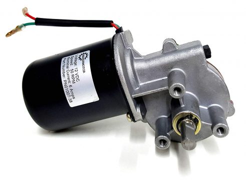
- Rated Voltage: 13.5 VDC
- 3/8″ shaft with 1 flat (“D” shaft) where flat to OD is 0.322″ and the length of the shaft is 0.886″ long
- Rated Speed: 50 RPM
- Mounting: M6 screw holes
- Rated Torque: 6 N-m (4.4 ft-lb)
About the 433Mhz Radio Frequency TX and RX modules:
I have a very detailed tutorial on how to use the 433Mhz Radio Frequency transmitter and receiver modules.
Solar Panel Used in this Project:
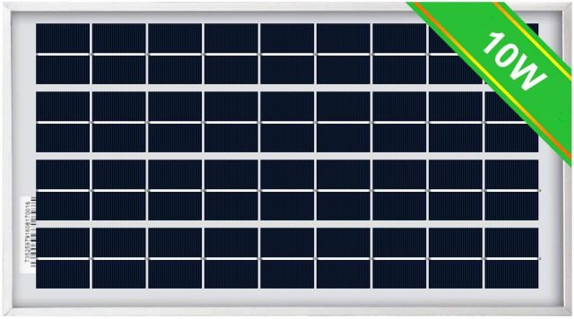
ECO-WORTHY 10W Solar Panel 10 Watt 12 Volt Pv Solar Module, Solar Cell Panel
Click on the link below if you want to check out 5 watts, 25 watts kit, and 25 watts.
Hybrid Robot Transmitter Circuit Diagram:

The Hybrid Robot transmitter side circuit is very simple as you can see in the circuit diagram above. The Arduino Uno is powered up using a 9 volt battery. 8 Pushbuttons are connected with the Arduino Uno. As you can see one side of all the Pushbuttons are connected with the ground, while the other sides of all the Pushbuttons are connected with the Arduino Uno I/O pins.
The Pushbutton S1 which is connected with the Arduino’s pin number 2 is used to control the Forward movement of the Hybrid Robot. The Pushbuttons S2 and S3 which are connected with the Arduino’s pin number 4 and pin number 3 are used to control the Right and Left movement of the Hybrid Robot. The S4 switch which is connected with the Arduino’s pin number 5 is used to control the Reverse movement of the Hybrid Robot; you can also use this Pushbutton for stopping the Hybrid Robot.
The Pushbuttons S5 and S6 which are connected with the Arduino’s pin number 6 and pin number 7 are used to start and stop charging from the Solar Panel. The Pushbuttons S7 and S8 which are connected with the Arduino’s pin number 8 and pin number 9 are used to start and stop charging from the Wind Turbine.
The VCC pin of the 433Mhz RF transmitter module is connected with the Arduino’s 5v, ground of the transmitter module is connected with the Arduino’s ground while the Data pin of the 433Mhz RF transmitter module is connected with the Arduino’s pin number 12.
Note: you can increase the range a bit by soldering a wire with the Antenna pin of the Transmitter module.
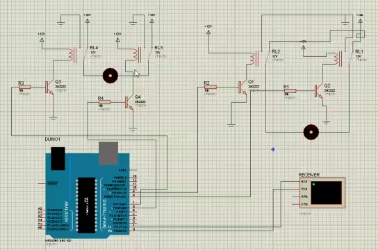
Hybrid Robot Receiver Circuit Diagram:

The Hybrid Robot receiver circuit looks a bit confusing or complex, but trust me it’s very simple and you will understand everything if you read the things I am going to explain.
The Arduino Uno and all the electronic components are powered up using the 12 volt Battery. All the ground are interconnected. Let’s start with the 433Mhz Radio Frequency receiver module. The VCC pin of the 433Mhz RF receiver module is connected with the Arduino’s 5v, ground of the receiver module is connected with the Arduino’s ground while the Data pin of the 433Mhz RF receiver module is connected with the Arduino’s pin number 11.
As you can see in the circuit diagram, each Motor is controlled using two relays. These relays are of the type SPDT “Single Pole Double Throw”. The connections of both the H-bridges are exactly the same except the Arduino pins. Let me explain what is an H-bridge and how it works.
An H-bridge is used to control the Forward and Reverse rotation/direction of the DC motor. The two relays in an H-bridge are used to change the polarity of the voltage supplied to the motor. As you can see in the circuit diagram, Normally Closed contacts of the relays are connected with the battery ground while the Normally Opened contacts of the relays are connected with the Battery 12 volts. While, the common contact of the relays are connected with the Motor terminals.
If you turn On one relay and keep the other relay OFF the motor rotates in one direction, and vice versa. The motor remains Off if both the relays are Turned OFF or Turned ON. If there is no change in the polarity the motor will remain OFF.
The two H-bridges are controlled using the Arduino’s pins 2, 3, 7, and 8. 5v from the Arduino turns on the relay, while the 0 “gnd” turns off the relay.
The two relays on the right side are used to control the charging of battery from the Solar Panel and Wind Turbine. You might have noticed one thing, I am using the same 2n2222 NPN transistors and 10k ohm resistors for controlling all the relays. The 2n2222 NPN transistor and 10k ohm resistor makes the relay driver circuit. Read my previous tutorial on the relay driver circuit designing and calculation.
Download H-Bridge Proteus Simulation: robot
I checked the H-bridge connections using the Proteus simulation. I successfully controlled both the motors.
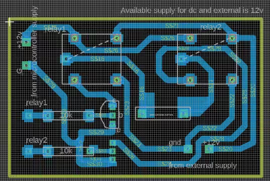
Download the H-bridge PCB board layout: relay hbridge
After, I was satisfied with the testing and all the connections, then finally, I designed a PCB board for the H-bridge. In an overload situation the copper wires can damage, I recommend apply solder to the wires this will increase the current ratings of the PCB wires.
Hybrid Robot Programming:
The Hybrid Robot project is based on two Arduino programs. One program is written for the Transmitter side Arduino, while the other Program is written for the Receiver side Arduino. Each program is well commented. If you still find anything confusing, you can let me know in a comment.
Hybrid Robot Transmitter Arduino Programming:
|
1 2 3 4 5 6 7 8 9 10 11 12 13 14 15 16 17 18 19 20 21 22 23 24 25 26 27 28 29 30 31 32 33 34 35 36 37 38 39 40 41 42 43 44 45 46 47 48 49 50 51 52 53 54 55 56 57 58 59 60 61 62 63 64 65 66 67 68 69 70 71 72 73 74 75 76 77 78 79 80 81 82 83 84 85 86 87 88 89 90 91 92 93 94 95 96 97 98 99 100 101 102 103 104 105 106 107 108 109 110 111 112 113 114 115 116 117 118 119 120 121 122 123 124 125 126 127 128 129 130 131 132 133 134 135 136 137 138 139 140 141 142 143 144 145 146 147 148 149 150 151 |
#include <VirtualWire.h> const int led_pin = 11; const int transmit_pin = 12; const int transmit_en_pin = 3; int button = 2; // for straight int button1 = 3; // right int button2 = 4; // left int button4 = 5; // stop int button5 = 6; // to start charging from solar int button6 = 7; // to stop charging from solar int button7 = 8; // to start charging from wind turbine int button8 = 9; // to stop charging from wind turbine. void setup() { // Initialise the IO and ISR vw_set_tx_pin(transmit_pin); pinMode(button, INPUT); pinMode(button1, INPUT); pinMode(button2, INPUT); pinMode(button4, INPUT); pinMode(button5, INPUT); pinMode(button6, INPUT); pinMode(button7, INPUT); pinMode(button8, INPUT); vw_setup(2000); // Bits per sec } byte count = 1; void loop() { char msg[7] = {'h'}; // straight char msg1[7] = {'j'}; // right char msg2[7] = {'l'}; // left char msg3[7] = {'m'}; // garbage value char msg8[7] = {'z'}; // stop // solar planel charge controlling char msg9[7] = {'s'}; // start charging from solar char msg10[7] = {'t'}; // stop charging from solar // wind turbine charge controlling char msg11[7] = {'w'}; // start charging from wind char msg12[7] = {'x'}; // stop charging from wind // msg[6] = count; if(digitalRead(button) == 0 ) { vw_send((uint8_t *)msg, 1); // change this number according to the sensor values vw_wait_tx(); // Wait until the whole message is gone delay(1000); } if(digitalRead(button1) == 0 ) { vw_send((uint8_t *)msg1, 1); // change this number according to the sensor values vw_wait_tx(); // Wait until the whole message is gone delay(1000); } if(digitalRead(button2) == 0 ) { vw_send((uint8_t *)msg2, 1); // change this number according to the sensor values vw_wait_tx(); // Wait until the whole message is gone delay(1000); } if(digitalRead(button4) == 0 ) { vw_send((uint8_t *)msg8, 1); // change this number according to the sensor values vw_wait_tx(); // Wait until the whole message is gone delay(1000); } // solar charging if(digitalRead(button5) == 0 ) { vw_send((uint8_t *)msg9, 1); // sends s to the receiver vw_wait_tx(); // Wait until the whole message is gone delay(1000); } if(digitalRead(button6) == 0 ) { vw_send((uint8_t *)msg10, 1); // sends t to the receiver vw_wait_tx(); // Wait until the whole message is gone delay(1000); } // wind charging if(digitalRead(button7) == 0 ) { vw_send((uint8_t *)msg11, 1); // sends w to the receiver vw_wait_tx(); // Wait until the whole message is gone delay(1000); } if(digitalRead(button8) == 0 ) { vw_send((uint8_t *)msg12, 1); // sends x to the receiver vw_wait_tx(); // Wait until the whole message is gone delay(1000); } else digitalWrite(button, HIGH); digitalWrite(button1,HIGH); digitalWrite(button2,HIGH); digitalWrite(button4,HIGH); digitalWrite(button5,HIGH); digitalWrite(button6,HIGH); digitalWrite(button7,HIGH); digitalWrite(button8,HIGH); } |
Hybrid Robot Receiver Arduino Programming:
|
1 2 3 4 5 6 7 8 9 10 11 12 13 14 15 16 17 18 19 20 21 22 23 24 25 26 27 28 29 30 31 32 33 34 35 36 37 38 39 40 41 42 43 44 45 46 47 48 49 50 51 52 53 54 55 56 57 58 59 60 61 62 63 64 65 66 67 68 69 70 71 72 73 74 75 76 77 78 79 80 81 82 83 84 85 86 87 88 89 90 91 92 93 94 95 96 97 98 99 100 101 102 103 104 105 106 107 108 109 110 111 112 113 114 115 116 117 118 119 120 121 122 123 124 125 126 127 128 129 130 131 132 133 134 135 136 137 138 139 140 141 142 143 144 145 146 147 148 149 150 151 152 153 154 155 156 157 158 159 160 161 162 163 164 165 166 167 168 169 170 171 172 173 174 175 176 177 178 179 180 181 182 |
#include <VirtualWire.h> const int led_pin = 13; int rightmotor1 = 2; // right side motor int rightmotor2 = 3; // left side motor int leftmotor1 = 7; int leftmotor2 = 8; int solar = 5; // relay connected for charging from solar int wind = 6; // relay connected fro charging from wind // we are using flags to stop the unnecessary repetition of code int sflag = 0; // solar flag int wflag = 0; // wind flag const int receive_pin = 11; void setup() { delay(1000); Serial.begin(9600); // Debugging only Serial.println("setup"); // Initialise the IO and ISR vw_set_rx_pin(receive_pin); vw_set_ptt_inverted(true); // Required for DR3100 vw_setup(2000); // Bits per sec vw_rx_start(); // Start the receiver PLL running pinMode(led_pin, OUTPUT); digitalWrite(led_pin, LOW); pinMode(rightmotor1, OUTPUT); pinMode(rightmotor2, OUTPUT); pinMode(leftmotor1, OUTPUT); pinMode(leftmotor2, OUTPUT); pinMode(solar, OUTPUT); pinMode(wind, OUTPUT); // keep all the motors low digitalWrite(rightmotor1, LOW); digitalWrite(rightmotor2, LOW); digitalWrite(leftmotor1, LOW); digitalWrite(leftmotor2, LOW); // keep charging low by default. digitalWrite(solar, LOW); digitalWrite(wind, LOW); } void loop() { uint8_t buf[VW_MAX_MESSAGE_LEN]; uint8_t buflen = VW_MAX_MESSAGE_LEN; if (vw_get_message(buf, &buflen)) // Non-blocking { int i; // Message with a good checksum received, dump it. Serial.print("Got: "); for (i = 0; i < buflen; i++) { char c = (buf[i]); if( c == 'z') { digitalWrite(led_pin , LOW); digitalWrite(led_pin, HIGH); digitalWrite(rightmotor1 , LOW); digitalWrite(rightmotor2 , HIGH); digitalWrite(leftmotor1 , LOW); digitalWrite(leftmotor2 , HIGH); Serial.print(c); Serial.print(' '); } if( c == 'j') // for right side { digitalWrite(rightmotor1 , LOW); digitalWrite(rightmotor2 , LOW); digitalWrite(led_pin, LOW); digitalWrite(leftmotor1 , LOW); digitalWrite(leftmotor2 , LOW); delay(200); digitalWrite(leftmotor1 , LOW); digitalWrite(leftmotor2 , LOW); delay(200); // digitalWrite(leftmotor1 , HIGH); // digitalWrite(leftmotor2 , LOW); Serial.print(c); Serial.print(' '); } if( c == 'h') // for straight { digitalWrite(led_pin, HIGH); digitalWrite(rightmotor1 , HIGH); digitalWrite(rightmotor2 , LOW); digitalWrite(leftmotor1 , HIGH); digitalWrite(leftmotor2 , LOW); Serial.print(c); Serial.print(' '); } if( c == 'l') // for left { digitalWrite(leftmotor1 , LOW); digitalWrite(leftmotor2 , LOW); digitalWrite(rightmotor1 , LOW); digitalWrite(rightmotor2 , LOW); delay(200); digitalWrite(rightmotor1 , LOW); digitalWrite(rightmotor2 , LOW); delay(200); // digitalWrite(leftmotor1 , LOW); // digitalWrite(leftmotor2 , HIGH); Serial.print(c); Serial.print(' '); } // for solar panel if(( c == 's') && (sflag == 0) )// On relay to start charging { digitalWrite(solar, HIGH); sflag = 1; Serial.println("charging from solar started"); } if(( c == 't') && (sflag == 1) )// STOP CHARGING { digitalWrite(solar, LOW); sflag = 0; Serial.println("charging from solar stoped"); } // for wind turbine if(( c == 'w') && (wflag == 0) )// On relay to start charging { digitalWrite(wind, HIGH); wflag = 1; Serial.println("Charging from wind turbine started"); } if(( c == 'x') && (wflag == 1) )// STOP CHARGING { digitalWrite(wind, LOW); wflag = 0; Serial.println("Charging from wind turbine Stopped"); } // garbage value if( c == 'm') { Serial.print(c); Serial.print(' '); } } } } |
Watch Video Tutorial:
Discover more from Electronic Clinic
Subscribe to get the latest posts sent to your email.


