Introduction to the Comparator and Working
Last Updated on July 4, 2022 by Engr. Shahzada Fahad
Comparator
A circuit that makes a comparison between two input signals or voltage levels is known as a comparator. In other words, if an operational amplifier is operated in an open looped mode (i.e. from output to input without any feedback), such a circuit is known as a voltage comparator. In figure 8.58, a comparator has been displayed. As there is no need to connect any additional external components along with a comparator, therefore its circuit is extremely simple. Basically, a comparator’s output reveals which of its two inputs is a high potential.
Figure 8.58
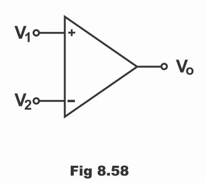
Suppose that two inputs (inverting and non- inverting) have been supplied on an operational amplifier’s circuit, while its output is the same, zero output is received in case both inputs are mutually equal. Now, if non- inverting input exceeds inverting input, comparator provides high output voltages. On the contrary, when non- inverting input is less compared to inverting input, comparator provides low output. In order to ascertain how does a comparator compare the two inputs signals and then provide output on this base, it is necessary to study the basic circuit of a comparator.
Working
We know that an operational amplifier is usually used in closed-loop mode (i.e. along with feedback), so that its voltage gain could be controlled accurately with the coordination of exterior components. It is never being used in open loop mode; because it’s extremely high open loop voltage saturates its output via any reasonable input signal. In order to understand how a comparator does compare two input signals and provides out on this base, the study of circuit shown in figure 8.59 is essential.
Figure 8.59 – Basic Op-Amp comparator circuit
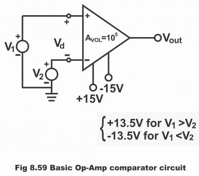
When operational circuit is applied without any feedback, it works as a comparator as is vivid from figure 8.59. In situation of amplifiers’ inverting input being grounded, minimum input voltages are required for its saturation. Thus, if differential gain of an operational amplifier is AVOL, minimum differential voltages (Vd) required for the purpose of its saturation can be determined via the following formula:
Vd = Vsat/ AVOL
Suppose if power supply is , the output swings between +13.5 to -13.5 (that’s output fluctuates between )If the open loop gain of an operational amplifier is 105, in such a situation, the minimum input voltage, on which saturation starts, will be as follows:
Vd = V1-V2 = 13.5/105 = 13.5 … µV
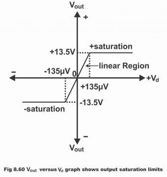
That is, for saturating an operational amplifier (741C) +135µV in positive while -135µV in negative direction would be required. When the value of V1 exceeds V2 (135µV or greater) output saturates in positive direction on +13.5V. On the contrary, when the value of V2 exceeds V1 (135µV or more) output saturates on -13.5V in negative direction, as has been displayed vide figure 8.60. Thus, remember that comparator’s output consists of just two stable states i.e. negative saturation and positive saturation.
Figure 8.60 – Vout versus Vd graph shows output saturation limits.
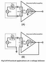
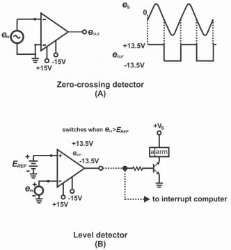
There are several applications or uses of a comparator, out of which two of the uses have been illustrated in figure 8.61. The circuit shown in figure (A) is called zero crossing detectors, because when es cross waveform 0V, eout swing from one saturation level to another. When es are positive, the value of eout tends to be +13.5V. When the value of es is lower than zero volts (0V), the value of eout becomes -13.5V. When es values rise above 0V, eout value gets back to +13.5V.
The circuit shown in figure (B) is called a level detector. When input signal (ein) is lower than a DC reference level (EREF), this level detector immediately identifies the situation (i.e. level detector identifies or recognizes two different levels). DC reference (EREF) has been connected with positive input whereas ein has been supplied with negative input. As long as value of ein is high as compared to EREF, up to that point operational amplifier’s output keeps saturated on -13.5V. However, when ein value is lower than EREF, amplifiers’ output keeps saturated on +13.5V. The output of a level detector can also be used to operate an alarm or its output can be transferred to a computer as well, so that alarm could be turned on as level changes or the operation could be stopped through a computer.
Figure 8.61- comparator applications
Next Topic: Difference Amplifier with Equation Example
Previous Topic: Introduction to the 741 OP AMP, Circuit Diagram, and working
For electronics and programming-related projects visit my YouTube channel.
Discover more from Electronic Clinic
Subscribe to get the latest posts sent to your email.