KY-038 Sound Sensor with Arduino Circuit & Code, Clap project
Table of Contents
KY-038 Sound Sensor with Arduino:
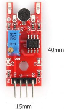
KY-038 Sound Sensor with Arduino– In this article, we will discuss about the sound detection microphone module known as KY-038. These microphone based sound sensor modules are small, easy to setup and very useful. I will explain in detail how to use the KY-038 Sound Sensor with the Arduino and without the arduino to control a robot. Someone who has difficulty in an alarm it can be used as an alarm to flash an LED. You could also use it as a presence detector to monitor sound levels or maybe to turn on some lights. You can also link it wirelessly to send notifications at a distance.The KY-38 sound sensor is very basic sound level detector module which features an electric condenser microphone. This module has integrated onboard one microphone, one potentiometer, one microchip, six resistors, and two LEDs.
The resistor R1 used in this module 10-kilo ohm, Resistor R2 is 100-kilo ohms, the resistor R3 is 150 ohm, the fourth resistor R4 is 1-kilo ohm, the resistor R5 is 1-kilo ohm, and theresistor R6 is 100-kilo ohms. The main reason for using the resistors is to limit current circulating inside the module, in other words to prevent current from burning the module. The LED L1 lightup to show if the module is working properly or not.
Now I will show how these components are connected together there we have the sensor itself and of course 6 resistors and 2 LEDs on the right you can see all the pins of the module are connected on this board, we have in black line which will show the flow of the ground wire, the red line show the the flow of the voltage, the green line “a” show the flow of the analog signal and we have another green line which will show the flow of the digital signal.
This module is used to detect the noise claps, hits, etc. it allows us to detect one sound has exceeded a set point, we have chosen so that the sensor can protect it. Sound is detected via a microphone and feed into the microchip itself. The detection of the sound level is adjusted via the potentiometer that’s on the board, in normal state the digital output of this module will be high but when the sensor detects something the digital output that the module will be low.
Features:
- It’s to be used for detecting the sound intensity of ambient. 2. Adjustable sensitivity (adjusted by the blue digital potentiometers)
- Operating voltage 3.3V-5V
- Output form: Digital switching outputs ( 0 and 1 high and low Level)
- Easy installation with bolt hole
- Small PCB Size :(L*W) 3.2* 1.7cm/1.26″*0.67″
Pins of the KY-038 Sound sensor:
This module consists of four pins
- The ground pin is represented with the G sign
- The voltage pin is represented with the “+” sign
- The analog pin is representedwith A0 sign
- The digital pin is represented with DS0 sign
So let’s talk about the signal, this module gives two signals which are analog and digital. We can connect the pin of the analog signal with any analog port and the pin of the digital signal with any digital port of different microcontroller boards like Arduino or Raspberry Pi.
amazon link:
Arduino Nano USB-C Type (Recommended)
*Please Note: These are affiliate links. I may make a commission if you buy the components through these links. I would appreciate your support in this way!
Control LED by Clap Using Arduino and Sound Sensor:
Now I am going to show you how to use a sound sensor and also controlling LED using clapping. The model name of the sound sensor is KY038. Now coming to the structure of this sensor as discussed above we have 4 pins first one is A0 that is analog output, second one pin G that is ground, third one is plus that is VCC, and we need to connect with five volt to the VCC, fourth one is do that is digital output. Apart from this we can see this potentiometer and two LEDs; potentiometer is used to control the sensitivity and led1 indicates the power and led2 indicates the sensitivity of the sound and the microphone is the sound sensor that basically sense the sound. There is another variety of this sensor also available in market that has only three pins.
So let’s look at how to set up the KY-038 sound sensor with the Arduino and easy steps to make a simple project. I am going to start with an Arduino UNO and a microphone sensor module you can of course do this with any kind of Arduino or you can adapt the idea for a Raspberry Pi or any other logic board.
Components Required:
Now to complete this project we need some components.
- Led
- KY-038 sound sensor
- 1K ohm resistor
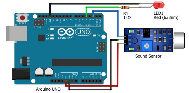
- Connect the ground of the sound sensor with the ground of the Arduino.
- Connect the VCC of KY-038 sound sensor with 5V of the Arduino.
- Connect the output of the sound sensor with the digital pin number 2.
- Now connect one positive terminal of the 1K ohm resistor with positive terminal of the led and connect other terminal of the resistor with the digital pin number 4
- Connect the cathode of the led with the ground of the arduino.
KY-038 Sound Sensor Arduino Code:
|
1 2 3 4 5 6 7 8 9 10 11 12 13 14 15 16 17 18 19 20 21 22 23 24 25 |
int soundSensor=2; int LED=4; boolean LEDStatus=false; void setup() { pinMode(soundSensor,INPUT); pinMode(LED,OUTPUT); } void loop() { int SensorData=digitalRead(soundSensor); if(SensorData==1){ if(LEDStatus==false){ LEDStatus=true; digitalWrite(LED,HIGH); } else{ LEDStatus=false; digitalWrite(LED,LOW); } } } |
Sound Sensor Arduino Code Explanation:
The code for this project is very simple. First we will define the pins which we are using in this project. As we are using 2 pins of the Arduino, so, we will define it such that:
int soundSensor = 2;
This shows that the sound sensor will be connected with the digital pin number 2.
int LED = 4 ;
The led will be connected with the digital pin number 4.
boolean LEDStatus = false;
Now we will define another variable ledstatus which will be either true or false.
Now in the setup we will define the pins which will be used as input and output. In our case we are using soundsensor as input and led as output.
void setup() {
pinMode(soundSensor,INPUT);
pinMode(LED,OUTPUT);
}
Now in the loop we will read the data of the sound sensor.
void loop() {
int SensorData=digitalRead(soundSensor);
Now if the sensor data will be true which means that it equal 1.
if(SensorData==1){
if(LEDStatus==false){
LEDStatus=true;
digitalWrite(LED,HIGH);
This command will turn on the led.
}
else{
LEDStatus=false;
digitalWrite(LED,LOW);
}
}
}
After uploading the code to the Arduino when we will clap led will be turned on and when we clap again the led will be turned off.
Sound sensor based Robot:
Now we will make a robot that will work on sound. It is very simple project that will work on sound for example when we will start talking it will start moving and when we stop talking the robot will be stopped or when the music will be played it will move and vice versa. This project need following components:
- KY-038 sound sensor
- Dc motors
- Motor driver
- Battery
- Jumper wires
Interfacing sound sensor with motor driver:
Now to connect the sound sensor with the motor driver we will connect the VCC of the motor driver with the VCC of the motor driver.
Connect the ground of the motor driver with the ground of the sound sensor and connect the output of the KY-038 sound sensor with IN1 and IN2 of the motor driver. Single output of the sound sensor will be connected with the two input of the motor driver. Now connect one dc motor with the motor driver such that +A will be connected with the one terminal of the motor and –A will be connected with the another terminal of the motor. Similarly, to connect the another motor we will connect the one terminal of the motor with +B and another terminal with the –B of the motor. Now connect the positive terminal of the battery with +V and negative with the ground.


i m electronics hobbyist , in my retired life now days , i m doing experiments on arduino my self , by you tube video . i likes respected you & Electronic Clinic too. thanks.