LoRa SX1278 and STM32 Temperature and Humidity Monitoring System
Last Updated on May 11, 2026 by Engr. Shahzada Fahad
Table of Contents
Lora SX1278 and STM32, Description:
In my STM32 and DHT11 getting started tutorial, I interfaced the DHT11 Temperature and Humidity Sensor with the STM32F103C microcontroller board and displayed the temperature and humidity values on the I2C supported SSD1306 Oled display Module. Today, I am going to modify this project by adding the Lora SX1278 long range wireless transceiver module.
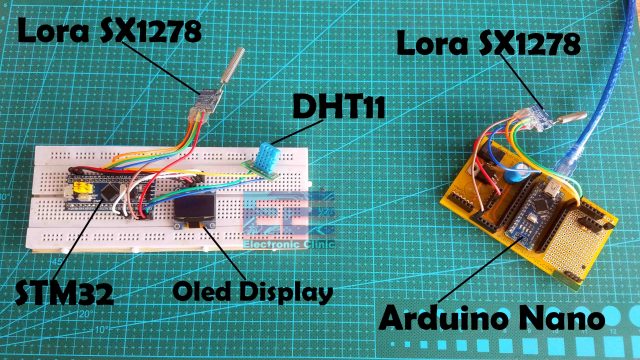
So, on the transmitter side I am using the Lora SX1278 with the STM32 and on the receiver side I am using the Lora SX1278 with the Arduino Nano. You might be thinking why STM32 on the Transmitter side and Arduino Nano on the receiver side? The answer is pretty straightforward, if you have been using Arduino boards then you should know the Arduino boards hangs a lot in the long run and for me it’s quite difficult to go and manually reset the Arduino board, so I decided to use the STM32F103C which is very fast as compared to the Arduino boards, stm32 may also get stuck but not as frequently as the Arduino boards. The reason I am using Arduino on the Receiver side is that, I have only one STM32 controller board, and moreover the receiver side will be in my room, and I will use it with my laptop to monitor the temperature and humidity values on the Serial monitor. So, most of the time the receiver side will be OFF. But the transmitter will remain ON. As the transmitter will remain ON for months so there is a high chance of the stm32 may get hanged, so this issue can be solved by using the watchdog timer, so if the stm32 gets hanged for the predefined time, the stm32 will automatically reset. I will make another tutorial about this, for now let’s forget about the watchdog timer.
So, before I am going to explain the Lora SX1278 interfacing with the STM32 and its programming; first let’s practically see how this system works. So, let’s go ahead and start with the Transmitter side.
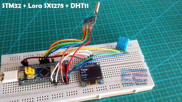
You can clearly see the Temperature and Humidity values on the Oled display module. As, I am near to the transmitter side, so there is no need to use the receiver, I can directly read the Temperature and Humidity values. Now, let’s say I am away from the transmitter then I can connect my receiver circuit with the laptop and then using the Serial monitor I can read the temperature and humidity values.

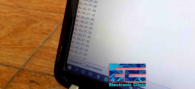
You can see the temperature and Humidity values are comma separated, I used comma as the delimiter which will help me in splitting the values.
In the next example I will convert this into a Lora Gateway that is we will be sending the temperature and humidity values to the IoT platform and this way we will be able to monitor the temperature and humidity values from anywhere in the world. Without any further delay let’s get started!!!
Amazon Links:
DHT11 Temperature and Humidity Sensor
SSD1306 128×64 Oled i2c display Module
Other Tools and Components:
Super Starter kit for Beginners
PCB small portable drill machines
*Please Note: These are affiliate links. I may make a commission if you buy the components through these links. I would appreciate your support in this way!
Transmitter side circuit diagram:

This is the transmitter side circuit diagram which explains how the Lora SX1278, DHT11, and Oled display modules are interfaced with the STM32 microcontroller board. A 10K ohm resistor is connected between the VDD and DATA pin of the DHT11 Temperature and Humidity Module.
The SSD1306 Oled display module Power supply pins are connected with the 3.3V and GND pins of the STM32 microcontroller board. The SCL and SDA pins of the Oled display module are connected with the B6 and B7 pins of the STM32. B6 is the SCL and B7 is the SDA.
The VCC and GND pins of the Lora module are connected with the 3.3V and GND pins of the STM32 controller board. MISO pin is connected with PA6, MOSI pin is connected with PA7, SLCK pin is connected with PA5, and the NSS pin is connected with the PA4 pin of the STM32. So, that’s all about the Transmitter side circuit diagram. Now, let’s take a look at the receiver side circuit diagram.
Receiver side circuit diagram:
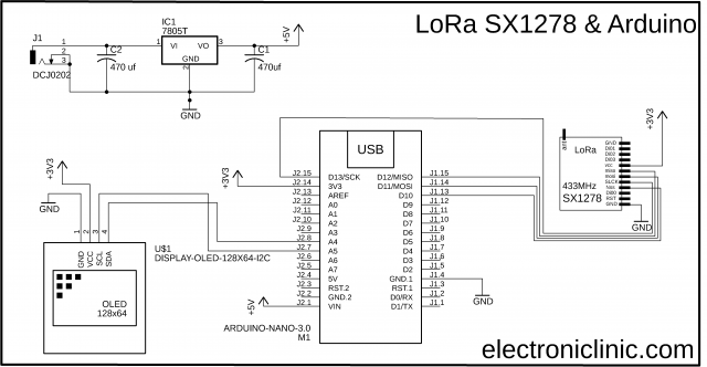
The VCC of the LoRa module is connected with the 3.3V of the Arduino. The MISO Pin of the LoRa module is connected with the Arduino’s pin 12. The MOSI pin is connected with the Arduino’s pin 11. The SCLK pin of the SX1278 LoRa module is connected with the Arduino’s pin 13. The NSS pin is connected with the Arduino’s pin 10 and the ground pin of the LoRa module is connected with the Arduino’s GND.
In the circuit diagram you can also see the SSD1306 I2C supported Oled display Module. I added this if incase you want to print the values on the Oled display module. The VCC and GND pins of the SSD1306 Oled display module are connected with the Arduino’s 3.3V and GND pins. The SDA and SCL pins of the Oled display module are connected with the Arduino’s I2C pins A4 and A5.
On the top you can see is the 5V regulated power supply based on the 7805 voltage regulator. You will need this power supply if you want to power up your Arduino using an external 12V power supply or a solar panel.
STM32 with Arduino IDE:
In order to program the STM32 microcontroller board using the Arduino IDE, first you will need to flash the STM32 bootloader and install drivers step by step, and you will also need to install the STM32 board, and some drivers. I have a very detailed tutorial on this and I highly recommend you should read my article on the STM32 Bootloader stm32F103c8t6. Now, let’s take a look at the programming. Now, let’s take a look at the programming.
Arduino Libraries:
STM32 Libraries:
Arduino Lora STM32 Library:
STM32 and Arduino Programming:
As this project is based on the wireless communication so, we have two programs, one program is written for the Transmitter side and the other program is written for the Receiver side. So, let’s first start with the Transmitter side programming.
STM32, SX1278 Lora, and DHT11 Programming:
|
1 2 3 4 5 6 7 8 9 10 11 12 13 14 15 16 17 18 19 20 21 22 23 24 25 26 27 28 29 30 31 32 33 34 35 36 37 38 39 40 41 42 43 44 45 46 47 48 49 50 51 52 53 54 55 56 57 58 59 60 61 62 63 64 65 66 67 68 69 70 71 72 73 74 75 76 77 78 79 80 81 82 83 84 85 86 87 88 89 90 91 92 93 94 95 96 97 98 |
/* * STM32 with DHT11 Temperature and Humidity sensor * DHT11 connected to PA2 * * Oled connection * B6 to SCL of Oled * B7 to SDA of Oled * * * Lora CONNECTIONS * SX1278 PINS STM32F103C * GND GND * VCC 3.3V * SCK PA5 * MISO PA6 * MOSI PA7 * NSS PA4 */ #include <Wire.h> //Library for using I2C #include <Adafruit_SSD1306_STM32.h> #include <DHT.h> //Library for using DHT sensor #include <LoRa_STM32.h> #define SS PA4 #define RST PB0 #define DI0 PA8 #define TX_P 17 #define BAND 433E6 #define ENCRYPT 0x78 #define DHTPIN PA2 #define DHTTYPE DHT11 DHT dht(DHTPIN, DHTTYPE); //initilize object dht for class DHT with DHT pin with STM32 and DHT type as DHT11 float h; float t; // for Oled display ssd1306 #define OLED_RESET -1 Adafruit_SSD1306 display(OLED_RESET); void setup() { Serial.begin(9600); display.begin(SSD1306_SWITCHCAPVCC, 0x3C); // initialize with the pinMode(DHTPIN, OUTPUT); dht.begin(); //Begins to receive Temperature and humidity values. LoRa.setTxPower(TX_P); LoRa.setSyncWord(ENCRYPT); LoRa.setPins(SS, RST, DI0); if (!LoRa.begin(BAND)) { Serial.println("Starting LoRa failed!"); while (1); } //Clear the buffer. display.clearDisplay(); } void loop() { h = dht.readHumidity(); //Gets Humidity value t = dht.readTemperature(); //Gets Temperature value DisplayData(); String MyMessage = ""; MyMessage = MyMessage + String(h) + "," + String(t); // send packet LoRa.beginPacket(); LoRa.print(MyMessage); LoRa.endPacket(); delay(100); } void DisplayData() { display.clearDisplay(); display.setTextSize(2); display.setTextColor(WHITE); display.setCursor(0,0); display.println("Temp:"); display.setTextSize(1); display.setCursor(0,20); // column , row display.println(t); display.setTextSize(2); display.setCursor(0,35); display.println("Hum:"); display.setTextSize(1); display.setCursor(0,55); // column , row display.println(h); display.display(); delay(100); } |
As you can see, this is the same exact program from my previous tutorial, this time I added code for the Lora SX1278 module. I started off by adding the library and defined some pins and variables.
Inside the loop() function,
|
1 2 3 4 5 6 7 |
String MyMessage = ""; MyMessage = MyMessage + String(h) + "," + String(t); // send packet LoRa.beginPacket(); LoRa.print(MyMessage); LoRa.endPacket(); delay(100); |
I only added this code which sends the humidity and temperature values. If you find it confusing then you can watch my complete series of videos on the Arduino and Lora SX1278. The programming style of the Arduino and STM32 is almost the same. Now, let’s take a look at the receiver side programming.
SX1278 Lora Arduino Programming:
|
1 2 3 4 5 6 7 8 9 10 11 12 13 14 15 16 17 18 19 20 21 22 23 24 25 26 27 28 29 30 31 32 33 34 35 36 37 38 39 40 41 42 43 44 45 46 47 48 49 50 51 52 |
/* * Temperature and Humidity Monitoring * Receiver side * * Module SX1278 // Arduino UNO/NANO GND -> GND Vcc -> 3.3V MISO -> D12 MOSI -> D11 SLCK -> D13 Nss -> D10 Di00 -> D2 RST -> D9 */ #include <SPI.h> #include <LoRa.h> String inString = ""; // string to hold input String MyMessage = ""; void setup() { Serial.begin(9600); while (!Serial); Serial.println("LoRa Receiver"); if (!LoRa.begin(433E6)) { // or 915E6 Serial.println("Starting LoRa failed!"); while (1); } } void loop() { // try to parse packet int packetSize = LoRa.parsePacket(); if (packetSize) { // read packet while (LoRa.available()) { int inChar = LoRa.read(); inString += (char)inChar; MyMessage = inString; } inString = ""; LoRa.packetRssi(); } Serial.println(MyMessage); } |
On the receiver side, I didn’t even change a single instruction. This is the same exact program which I explained in my Arduino and Lora based getting started tutorial. So, that’s all for now.
Watch Video Tutorial:

Troubleshooting — Problems You Will Likely Face and How to Fix Them
Problem 1: LoRa initialization fails on the STM32 — Serial Monitor shows “Starting LoRa failed”
This error appears right at startup and means the STM32 cannot communicate with the SX1278 module over SPI. The LoRa library tries to read a register from the SX1278 chip to confirm it is present — if nothing responds, it reports a failure.
The first thing to check is the SPI wiring. On the STM32F103C8T6 the default SPI1 pins are PA4 for NSS, PA5 for SCLK, PA6 for MISO, and PA7 for MOSI. These must match exactly what is defined in the code. If even one wire is going to the wrong pin, the SX1278 will not respond and the initialization fails every time.
The second thing to verify is the power supply to the SX1278. This module runs on 3.3V maximum — never connect it to 5V. Even a brief connection to 5V can permanently damage the RF circuitry inside the chip. Connect VCC to the STM32’s 3.3V pin only. Also make sure the GND of the LoRa module is directly connected to the STM32 GND — not through a long breadboard path with multiple intermediate connections, as ground resistance causes communication errors.
Finally, check that the antenna wire is soldered to the antenna pad on the SX1278 module. Some SX1278 modules refuse to initialize correctly without an antenna attached because the RF feedback circuit detects an open antenna condition.
Problem 2: STM32 transmitter is running but Arduino Nano receiver shows nothing received
The STM32 transmitter is clearly working — you can see activity on the OLED display and the Serial Monitor shows data being sent. But on the receiver side, the Arduino Nano Serial Monitor shows absolutely nothing coming in.
This almost always means the LoRa parameters do not match between the two sides. Both the transmitter and receiver must be configured with identical frequency, spreading factor, signal bandwidth, and coding rate. Go through both sketches line by line and confirm every single LoRa setting is identical. A single difference — even the bandwidth — means the two modules cannot understand each other even if they are sitting right next to each other.
Also check that both LoRa modules are the same frequency version. The 433MHz version and the 868MHz version of the SX1278 look identical physically but operate in completely different frequency ranges. If you accidentally bought one 433MHz and one 868MHz module they will never communicate no matter how perfectly you match the software settings.
Problem 3: DHT11 returns 255 for both temperature and humidity on the STM32
Getting 255 from DHT11 on STM32 is one of the most well-known issues in the STM32 community and Engr. Shahzada Fahad specifically addressed it in the previous STM32 and DHT11 tutorial on this site. The standard Arduino DHT library does not work correctly with STM32 because the STM32’s timing is fundamentally different from an AVR-based Arduino.
The fix is to use the specific DHT library version provided in that tutorial — not the one from the Arduino Library Manager. Download the exact library from the link in the STM32 and DHT11 article on this site and install it by copying it manually into your Arduino libraries folder. After installing the correct library, also confirm that the 10K pull-up resistor is connected between the DHT11 VDD and DATA pins. Without this resistor, even the correct library cannot read the sensor reliably.
Problem 4: Receiver is getting data but the temperature and humidity values are being printed as one long merged number
On the receiver side, the incoming LoRa packet contains a comma-separated string like “28.5,65.2”. If the parsing is not done correctly, the Serial Monitor shows something like “28565.2” or a completely garbled number instead of two separate values.
The issue is in how the received string is being split. The code uses the comma character as a delimiter to separate temperature from humidity. If the indexOf() and substring() calls are not finding the comma correctly, the entire string gets interpreted as a single value. Print the raw received string to Serial Monitor first — before any parsing — so you can see exactly what bytes arrived. If the raw string looks correct like “28.5,65.2” but parsing fails, check whether a newline character is being appended to the end of the string which sometimes shifts the indexOf result. Trim the received string before parsing using the trim() function.
Problem 5: Communication range is only a few meters instead of the hundreds of meters expected
LoRa is supposed to cover hundreds of meters or even kilometers but your setup barely reaches across the room. This is a very frustrating problem and it almost always comes down to antenna issues or incorrect spreading factor settings.
First check the antenna. The wire antenna supplied with cheap SX1278 modules from Chinese suppliers is often cut to the wrong length or not soldered properly to the antenna pad. For 433MHz, the correct quarter-wavelength antenna is exactly 164 millimeters of wire. Measure yours and trim or extend it to this precise length. Even being 10mm off noticeably reduces range.
Second, check the spreading factor in your code. A spreading factor of SF7 gives the fastest data rate but the shortest range. SF12 gives the longest range but the slowest data rate. For a temperature sensor that sends data every few seconds, use SF10 or SF11 — you gain dramatic range improvement at the cost of slightly slower transmission which does not matter at all for this application.
Third, make sure both antennas are oriented the same way — both vertical or both horizontal. Mismatched antenna orientation can reduce signal strength by 20dB which is a factor of 100 in received power.
Problem 6: STM32 hangs after running for several hours and stops transmitting
Engr. Shahzada Fahad actually mentioned this in the article — STM32 boards can occasionally freeze during long continuous operation, though less frequently than Arduino. The solution he planned to cover in a future tutorial is the hardware watchdog timer.
On the STM32, the Independent Watchdog (IWDG) is a hardware timer that resets the microcontroller automatically if the firmware stops refreshing it within a set timeout period. To enable it, call IWatchdog.begin(4000000) in your setup to set a 4-second timeout, and call IWatchdog.reload() inside your main loop at least once per loop cycle. If the STM32 hangs for any reason and stops reaching that reload call for more than 4 seconds, the watchdog automatically triggers a hardware reset and the system restarts cleanly. This single addition makes an unattended transmitter node genuinely reliable for weeks of continuous operation without manual intervention.
Frequently Asked Questions
Why did Engr. Shahzada Fahad use STM32 on the transmitter side instead of Arduino?
This is a practical reliability decision based on real experience. Arduino boards — particularly the Uno and Nano — occasionally freeze or hang during extended continuous operation, especially when running complex timing-sensitive code like DHT11 reading combined with SPI communication. In a transmitter node that is expected to run for weeks or months unattended in a remote location, a freeze that requires a manual reset is unacceptable. The STM32F103C8T6 is significantly more stable for long-running applications. It has a faster processor, better memory management, and as explained in the troubleshooting section above, it has a proper hardware watchdog timer that can automatically recover from a freeze. For a node that sits in a field monitoring temperature continuously, that reliability difference matters enormously.
Can I use two Arduino Nano boards instead of STM32 and Arduino Nano?
Yes, completely. If you do not have an STM32 board or prefer to stay within the familiar Arduino environment, two Arduino Nano boards work perfectly for this project. The LoRa library and DHT11 library both work on Arduino Nano. The SPI wiring on the Arduino Nano is pin 12 for MISO, pin 11 for MOSI, pin 13 for SCLK, and pin 10 for NSS. The trade-off is that Arduino Nano is slightly less stable for very long-term unattended operation compared to STM32. Adding the watchdog timer using the avr/wdt.h library on Arduino mitigates this risk significantly.
What is the maximum distance this project can cover outdoors?
With the correct 164mm wire antenna at 433MHz and the spreading factor set to SF10 or higher, this setup can reliably cover 500 meters to 2 kilometers in a typical suburban environment with buildings and trees. In an open agricultural field with no obstructions and line-of-sight between transmitter and receiver, you can realistically expect 5 to 10 kilometers. The sensitivity of the SX1278 at -139dBm is one of the best available in this price range. Real-world range always falls below theoretical maximum due to ground reflections, vegetation, and building penetration losses, but even at reduced range LoRa comfortably outperforms any other low-cost wireless technology for this type of application.
Can I add more sensors to the transmitter and send more data per packet?
Absolutely. The current setup sends a simple comma-separated string of two values. You can extend this to include as many sensors as you need. Add a soil moisture sensor, a rain sensor, a CO2 sensor — whatever is relevant to your application. Just add each new value to the string separated by a comma before sending. On the receiver side, extend the parsing to split on commas and extract the additional values. The maximum LoRa packet size is 255 bytes which is more than enough to include dozens of sensor readings in text format without any issues.
Can this project be upgraded to send data to the internet from the receiver side?
Yes and that is exactly what the follow-up tutorial on this site does. By replacing the Arduino Nano receiver with an ESP8266 NodeMCU, the receiver becomes an IoT gateway that takes data arriving over LoRa and forwards it to Blynk, ThingSpeak, or Google Sheets over WiFi. The transmitter STM32 side stays completely unchanged. This is a powerful architecture for remote monitoring — LoRa handles the long-range wireless link from the sensor location to the gateway, and WiFi handles the last mile to the internet. If you want to monitor temperature and humidity from anywhere in the world on your phone, read the ESP8266 LoRa Gateway article which is the next step in this series.
Does this project work in the rain or outdoor conditions?
The electronics as built in this tutorial are not weatherproof. If you want to deploy this as a permanent outdoor sensor node, you need to house everything in a waterproof enclosure. Use a proper IP65 or IP67 rated outdoor electrical junction box — available from hardware stores. Mount the DHT11 sensor in a radiation shield which is a small louvered housing that protects the sensor from rain and direct sunlight while allowing airflow for accurate readings. Run the antenna wire out through a cable gland to maintain the weatherproof seal. The SX1278 LoRa module itself handles temperature extremes well — its operating range of minus 40 to plus 85 degrees Celsius covers virtually all outdoor environments worldwide.
If you have questions about the STM32 setup or the LoRa communication range in your specific environment, describe your situation in the comments below and I will give you practical advice based on real experience with this exact hardware.
Discover more from Electronic Clinic
Subscribe to get the latest posts sent to your email.
Your needs come first! Purplewaveindia has no agendas, and no loyalties to anyone other than you, our client. Purplewaveindia was established in 2018. And in a short span of 4-years, Purplewaveindia has become one of the prominent players in the Indian Audio Video Manufacturing and Integration Industry.
Hello! Could you make changes to the receiver sketch to connect the SSD1306 Oled and display the data received on it? Your project is amazing, don’t abandon this project because you can add functions for turning on a relay (fan or heater) and feedback that controls the operation of these relays. My knowledge is only enough to repeat your project, and not change it. Good luck to you!
Hi,
Thank you for this post, its very good example to start lora communication with different platform,
I tried and its working for me,
My question, from Tx side, can I use stm8l ic to send data Arduino based Rx.
For reference of stm8l with lora, I want to use “https://github.com/Exboom/LoRa_STM8/tree/master”
Please suggest.