STM32 Bluetooth Home Automation Project Using STM32CubeIDE with Feedback
Last Updated on May 8, 2026 by Engr. Shahzada Fahad
Table of Contents
STM32 Bluetooth:
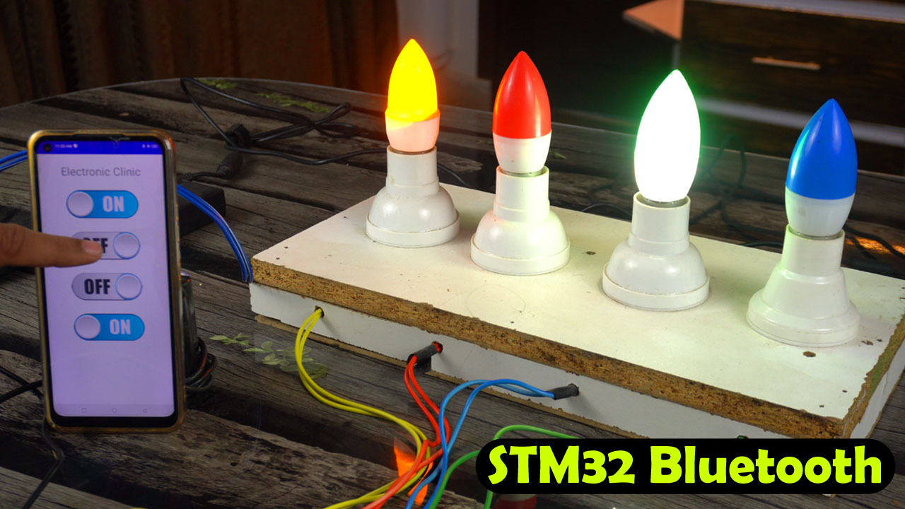
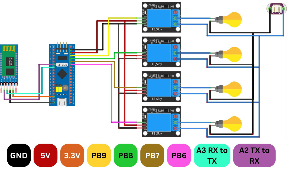
STM32 Bluetooth Home Automation with Feedback, STM32CubeIDE– Today, we are going to make the world’s fastest Home Automation system using the STM32F103C8T6 controller board, HC05 or HC06 Bluetooth Module, a Solid-state 4-channels relay module, and an android cell phone application designed in Android Studio.
Now, you might be wondering, “Why not just use Arduino for this job?” Well, buckle up as we unravel the reasons why STM32 steals the spotlight in this home automation extravaganza.
Arduino has long been a favorite for DIY projects, but STM32 is preferred over the Arduino for more complex projects due to its advanced ARM Cortex-M architecture, offering higher processing power, larger memory, and a wide range of peripherals. It excels in multitasking, real-time capabilities, and provides a more robust development environment, making it ideal for applications that demand performance and scalability beyond the capabilities of Arduino.
During initial experiments, I used mechanical relays that we commonly use. Even now, I can control loads at a considerable speed, and I believe this switching speed is sufficient. However, my goal is to create the world’s fastest home automation system, and achieving this is not possible by using mechanical relays.
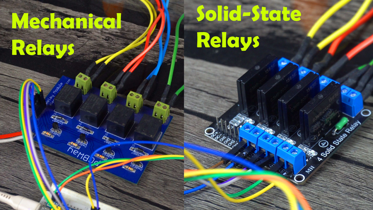
Mechanical relays are slow due to the physical movement involved in their operation. The mechanical parts, such as contacts, have inertia, leading to delays in switching. Additionally, contact bounce, where contacts make and break several times before stabilizing, contributes to the overall response time. The energizing and de-energizing of the relay coil also take time, influenced by both electrical and mechanical factors. And because there are moving parts in it, the lifespan of mechanical relays is also reduced due to wear and tear.
Anyway, I replaced the mechanical relays with the Solid-state relays and then I was like wow.

In contrast, solid-state relays (SSRs) use electronic components for switching, eliminating mechanical parts and offering faster response times, making them more suitable for applications requiring rapid and precise switching.
This home automation system is not only faster but also quite user-friendly. As you can see, I have some loads currently switched on.
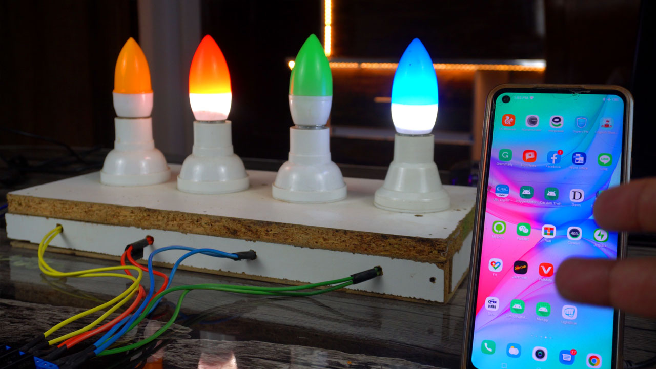
For now, let’s imagine these loads are installed in another room. After a couple of hours, I want to switch one of these loads on or off, but I’ve forgotten which one I turned ON or turned OFF. To eliminate this kind of confusion, I’ve integrated a feedback feature into this home automation system. As soon as I open the application on my cell phone, STM32, through Bluetooth, provides me with feedback on which load is currently on and which one is off.
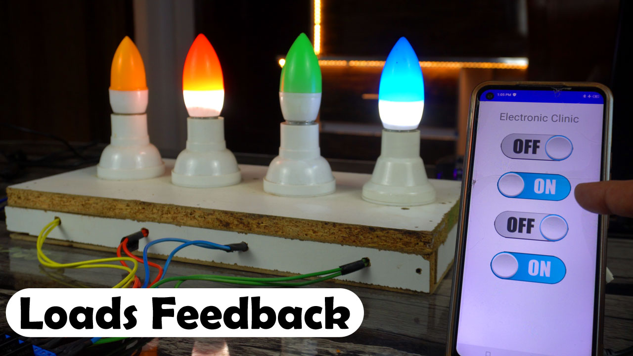
This ensures seamless control and eliminates any confusion.
What are your thoughts on this feedback idea? Drop a comment and let me know!
You can program the STM32 controller board using the Arduino IDE, I have explained it in several videos and articles, and you can also program the STM32 controller board using the STM32CubeIDE, and I have explained it in my 45 minutes long video and article “STM32 CubeIDE course”.
Anyway, using STM32CubeIDE over Arduino IDE for programming the STM32 controller board offers several advantages. STM32CubeIDE is tailored specifically for STM32 microcontrollers, providing advanced debugging features, a graphical interface for peripheral configuration, and seamless integration with STM32CubeMX.
Its support for complex projects, real-time capabilities, and optimized code generation make it superior for leveraging the full potential of STM32 architecture. In contrast, Arduino IDE, designed for simplicity, may lack the sophisticated tools required for complex STM32 applications. STM32CubeIDE streamlines development with a comprehensive ecosystem, making it the preferred choice for developers aiming for efficiency, precision, and optimal performance in STM32-based projects.
Note: Read my article on ESP32 and Low Energy BLE Application.
Amazon Links:
Other Tools and Components:
Super Starter kit for Beginners
PCB small portable drill machines
*Please Note: These are affiliate links. I may make a commission if you buy the components through these links. I would appreciate your support in this way!
Stm32 Bluetooth, Circuit diagram:
About STM32 Cube IDE:
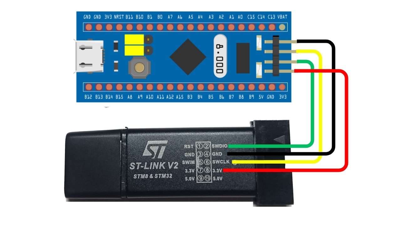
I have already created a 45-minute video on the STM32 and CubeIDE, where I explained the technical specifications of the STM32 board, I explained its pin configurations, demonstrated how to upload a program to the STM32 board using ST-link V2, and I have also explained how to setup your STM32CubeIDE. I’ve covered every detail comprehensively. Therefore, I highly recommend that you watch that video because I won’t be explaining those things again right now. You can also read my article on “STM32 course”.
Connect your STM32 board to the Laptop via ST-link V2; you can follow this connections diagram.
STM32 Bluetooth Programming:
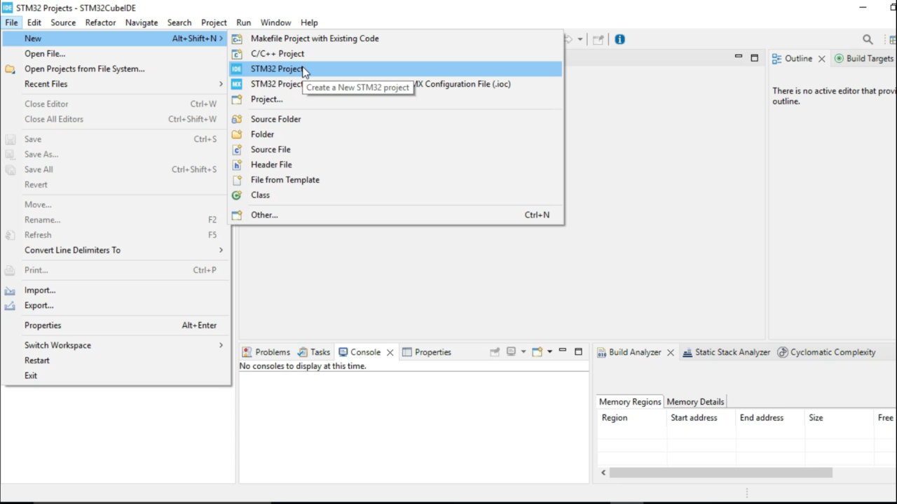
While the STM32CubeIDE is open; to start a new project, go to the File then to New, and click on the STM32 Project.
STM32CubeIDE may take a moment to load and download the necessary libraries. Please be patient during this process as it may take some time depending on the speed.
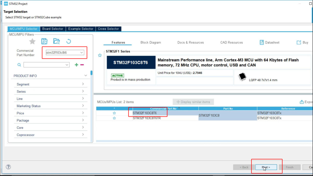
On the Target Selection Window and while the MCU Selector Tab is active; select the Commercial Part Number that is STM32F103C8T6, Select it from the MCUs list and then click on the Next Button.
Write the project name.
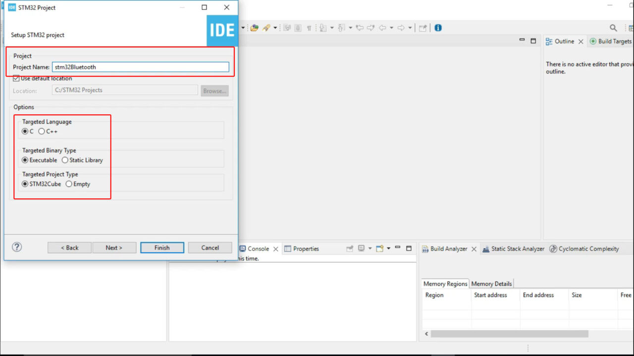
Select the
- Targeted Language.
- Target Binary Type. and
- Targeted Project Type.
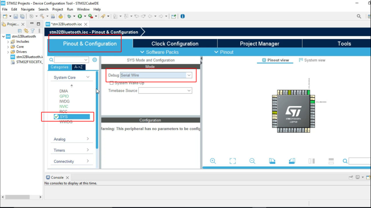
On the Pinout & Configuration Tab click on the System Core and select SYS. Click on the Debug and select Serial Wire.
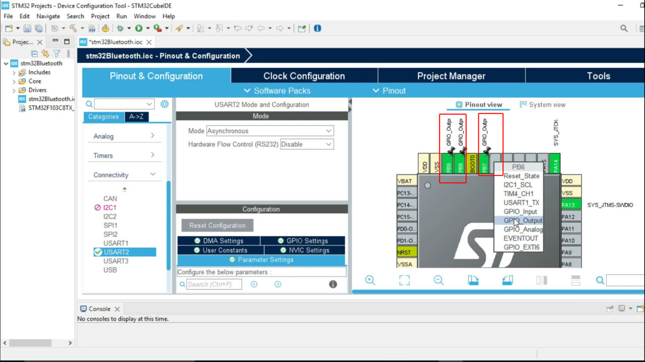
Next, click on the USART2 and on the Mode drop down menu select Asynchronous.

Next, we are going to set the GPIO pins PB9, PB8, PB7, and PB6 as the outputs. We are using these pins to control a 4-channels relay module.
Finally, click on the save button if it asks you Do you want to generate Code? click yes, again press the yes button. STM32CubeIDE will generate the necessary code based on your pin configuration and open the associated perspective. This perspective provides you with the appropriate tools and views for further development and customization of your project.
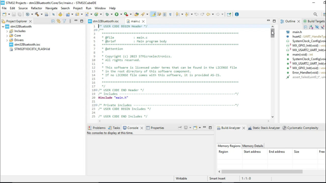
This is the generated code and now we will need to modify it in order to control the loads and send the feedback message to the android cell phone application. I have already done it. You will need to download the following code, next select the generated code, delete it and paste the following code.
STM32 CubeIDE Code:
|
1 2 3 4 5 6 7 8 9 10 11 12 13 14 15 16 17 18 19 20 21 22 23 24 25 26 27 28 29 30 31 32 33 34 35 36 37 38 39 40 41 42 43 44 45 46 47 48 49 50 51 52 53 54 55 56 57 58 59 60 61 62 63 64 65 66 67 68 69 70 71 72 73 74 75 76 77 78 79 80 81 82 83 84 85 86 87 88 89 90 91 92 93 94 95 96 97 98 99 100 101 102 103 104 105 106 107 108 109 110 111 112 113 114 115 116 117 118 119 120 121 122 123 124 125 126 127 128 129 130 131 132 133 134 135 136 137 138 139 140 141 142 143 144 145 146 147 148 149 150 151 152 153 154 155 156 157 158 159 160 161 162 163 164 165 166 167 168 169 170 171 172 173 174 175 176 177 178 179 180 181 182 183 184 185 186 187 188 189 190 191 192 193 194 195 196 197 198 199 200 201 202 203 204 205 206 207 208 209 210 211 212 213 214 215 216 217 218 219 220 221 222 223 224 225 226 227 228 229 230 231 232 233 234 235 236 237 238 239 240 241 242 243 244 245 246 247 248 249 250 251 252 253 254 255 256 257 258 259 260 261 262 263 264 265 266 267 268 269 270 271 272 273 274 275 276 277 278 279 280 281 282 283 284 285 286 287 288 289 290 291 292 293 294 295 296 297 298 299 300 301 302 303 304 305 306 307 308 309 310 311 312 313 314 315 316 317 318 319 320 321 322 323 |
/* USER CODE BEGIN Header */ /** ****************************************************************************** * @file : main.c * @brief : Main program body ****************************************************************************** * @attention * * Copyright (c) 2023 STMicroelectronics. * All rights reserved. * * This software is licensed under terms that can be found in the LICENSE file * in the root directory of this software component. * If no LICENSE file comes with this software, it is provided AS-IS. * ****************************************************************************** */ /* USER CODE END Header */ /* Includes ------------------------------------------------------------------*/ #include "main.h" #include <string.h> /* Private includes ----------------------------------------------------------*/ /* USER CODE BEGIN Includes */ /* USER CODE END Includes */ /* Private typedef -----------------------------------------------------------*/ /* USER CODE BEGIN PTD */ /* USER CODE END PTD */ /* Private define ------------------------------------------------------------*/ /* USER CODE BEGIN PD */ /* USER CODE END PD */ /* Private macro -------------------------------------------------------------*/ /* USER CODE BEGIN PM */ /* USER CODE END PM */ /* Private variables ---------------------------------------------------------*/ UART_HandleTypeDef huart2; uint8_t rx_data = 0; char tx_data[90]; uint8_t led1_state = 0; // Initial state is off uint8_t led2_state = 0; // Initial state is off uint8_t led3_state = 0; // Initial state is off uint8_t led4_state = 0; // Initial state is off /* USER CODE BEGIN PV */ /* USER CODE END PV */ /* Private function prototypes -----------------------------------------------*/ void SystemClock_Config(void); static void MX_GPIO_Init(void); static void MX_USART2_UART_Init(void); /* USER CODE BEGIN PFP */ /* USER CODE END PFP */ /* Private user code ---------------------------------------------------------*/ /* USER CODE BEGIN 0 */ /* USER CODE END 0 */ /** * @brief The application entry point. * @retval int */ int main(void) { /* USER CODE BEGIN 1 */ /* USER CODE END 1 */ /* MCU Configuration--------------------------------------------------------*/ /* Reset of all peripherals, Initializes the Flash interface and the Systick. */ HAL_Init(); /* USER CODE BEGIN Init */ /* USER CODE END Init */ /* Configure the system clock */ SystemClock_Config(); /* USER CODE BEGIN SysInit */ /* USER CODE END SysInit */ /* Initialize all configured peripherals */ MX_GPIO_Init(); MX_USART2_UART_Init(); /* USER CODE BEGIN 2 */ //HAL_GPIO_WritePin(GPIOB, GPIO_PIN_9, 0); /* USER CODE END 2 */ /* Infinite loop */ /* USER CODE BEGIN WHILE */ HAL_UART_Transmit(&huart2, (uint8_t*)"AT\r\n", 4, HAL_MAX_DELAY); // Send "AT" to check if HC-05 is responsive HAL_Delay(1000); // Wait for the module to respond while (1) { if (HAL_UART_Receive(&huart2, &rx_data, 1, 100) == HAL_OK) { // Control LED based on received data ControlLED(rx_data); } /* USER CODE END WHILE */ /* USER CODE BEGIN 3 */ //HAL_Delay(500); SendLEDStates(); } /* USER CODE END 3 */ } void ControlLED(uint8_t command) { if (command == '9') { // Turn off the LED HAL_GPIO_WritePin(GPIOB, GPIO_PIN_9, 1); led1_state=1; } else if (command == '2') { // Turn on the LED HAL_GPIO_WritePin(GPIOB, GPIO_PIN_9, 0); led1_state=0; } if (command == '3') { // Turn off the LED HAL_GPIO_WritePin(GPIOB, GPIO_PIN_8, 1); led2_state=1; } else if (command == '4') { // Turn on the LED HAL_GPIO_WritePin(GPIOB, GPIO_PIN_8, 0); led2_state=0; } if (command == '5') { // Turn off the LED HAL_GPIO_WritePin(GPIOB, GPIO_PIN_7, 1); led3_state=1; } else if (command == '6') { // Turn on the LED HAL_GPIO_WritePin(GPIOB, GPIO_PIN_7, 0); led3_state=0; } if (command == '7') { // Turn off the LED HAL_GPIO_WritePin(GPIOB, GPIO_PIN_6, 1); led4_state=1; } else if (command == '8') { // Turn on the LED HAL_GPIO_WritePin(GPIOB, GPIO_PIN_6, 0); led4_state=0; } } void SendLEDStates() { // Create a comma-separated array with LED states sprintf(tx_data, "%d,%d,%d,%d,\r\n" ,led1_state,led2_state,led3_state,led4_state); // Send the LED states HAL_UART_Transmit(&huart2, (uint8_t*)tx_data, strlen(tx_data), HAL_MAX_DELAY); } /** * @brief System Clock Configuration * @retval None */ void SystemClock_Config(void) { RCC_OscInitTypeDef RCC_OscInitStruct = {0}; RCC_ClkInitTypeDef RCC_ClkInitStruct = {0}; /** Initializes the RCC Oscillators according to the specified parameters * in the RCC_OscInitTypeDef structure. */ RCC_OscInitStruct.OscillatorType = RCC_OSCILLATORTYPE_HSI; RCC_OscInitStruct.HSIState = RCC_HSI_ON; RCC_OscInitStruct.HSICalibrationValue = RCC_HSICALIBRATION_DEFAULT; RCC_OscInitStruct.PLL.PLLState = RCC_PLL_NONE; if (HAL_RCC_OscConfig(&RCC_OscInitStruct) != HAL_OK) { Error_Handler(); } /** Initializes the CPU, AHB and APB buses clocks */ RCC_ClkInitStruct.ClockType = RCC_CLOCKTYPE_HCLK|RCC_CLOCKTYPE_SYSCLK |RCC_CLOCKTYPE_PCLK1|RCC_CLOCKTYPE_PCLK2; RCC_ClkInitStruct.SYSCLKSource = RCC_SYSCLKSOURCE_HSI; RCC_ClkInitStruct.AHBCLKDivider = RCC_SYSCLK_DIV1; RCC_ClkInitStruct.APB1CLKDivider = RCC_HCLK_DIV1; RCC_ClkInitStruct.APB2CLKDivider = RCC_HCLK_DIV1; if (HAL_RCC_ClockConfig(&RCC_ClkInitStruct, FLASH_LATENCY_0) != HAL_OK) { Error_Handler(); } } /** * @brief USART2 Initialization Function * @param None * @retval None */ static void MX_USART2_UART_Init(void) { /* USER CODE BEGIN USART2_Init 0 */ /* USER CODE END USART2_Init 0 */ /* USER CODE BEGIN USART2_Init 1 */ /* USER CODE END USART2_Init 1 */ huart2.Instance = USART2; huart2.Init.BaudRate = 9600; huart2.Init.WordLength = UART_WORDLENGTH_8B; huart2.Init.StopBits = UART_STOPBITS_1; huart2.Init.Parity = UART_PARITY_NONE; huart2.Init.Mode = UART_MODE_TX_RX; huart2.Init.HwFlowCtl = UART_HWCONTROL_NONE; huart2.Init.OverSampling = UART_OVERSAMPLING_16; if (HAL_UART_Init(&huart2) != HAL_OK) { Error_Handler(); } /* USER CODE BEGIN USART2_Init 2 */ /* USER CODE END USART2_Init 2 */ } /** * @brief GPIO Initialization Function * @param None * @retval None */ static void MX_GPIO_Init(void) { GPIO_InitTypeDef GPIO_InitStruct = {0}; /* USER CODE BEGIN MX_GPIO_Init_1 */ /* USER CODE END MX_GPIO_Init_1 */ /* GPIO Ports Clock Enable */ __HAL_RCC_GPIOA_CLK_ENABLE(); __HAL_RCC_GPIOB_CLK_ENABLE(); /*Configure GPIO pin Output Level */ HAL_GPIO_WritePin(GPIOB, GPIO_PIN_6|GPIO_PIN_7|GPIO_PIN_8|GPIO_PIN_9, GPIO_PIN_RESET); /*Configure GPIO pins : PB6 PB7 PB8 PB9 */ GPIO_InitStruct.Pin = GPIO_PIN_6|GPIO_PIN_7|GPIO_PIN_8|GPIO_PIN_9; GPIO_InitStruct.Mode = GPIO_MODE_OUTPUT_PP; GPIO_InitStruct.Pull = GPIO_NOPULL; GPIO_InitStruct.Speed = GPIO_SPEED_FREQ_LOW; HAL_GPIO_Init(GPIOB, &GPIO_InitStruct); /* USER CODE BEGIN MX_GPIO_Init_2 */ /* USER CODE END MX_GPIO_Init_2 */ } /* USER CODE BEGIN 4 */ /* USER CODE END 4 */ /** * @brief This function is executed in case of error occurrence. * @retval None */ void Error_Handler(void) { /* USER CODE BEGIN Error_Handler_Debug */ /* User can add his own implementation to report the HAL error return state */ __disable_irq(); while (1) { } /* USER CODE END Error_Handler_Debug */ } #ifdef USE_FULL_ASSERT /** * @brief Reports the name of the source file and the source line number * where the assert_param error has occurred. * @param file: pointer to the source file name * @param line: assert_param error line source number * @retval None */ void assert_failed(uint8_t *file, uint32_t line) { /* USER CODE BEGIN 6 */ /* User can add his own implementation to report the file name and line number, ex: printf("Wrong parameters value: file %s on line %d\r\n", file, line) */ /* USER CODE END 6 */ } #endif /* USE_FULL_ASSERT */ |
Finally, click the save button and then click on the Hammer Icon or Build.
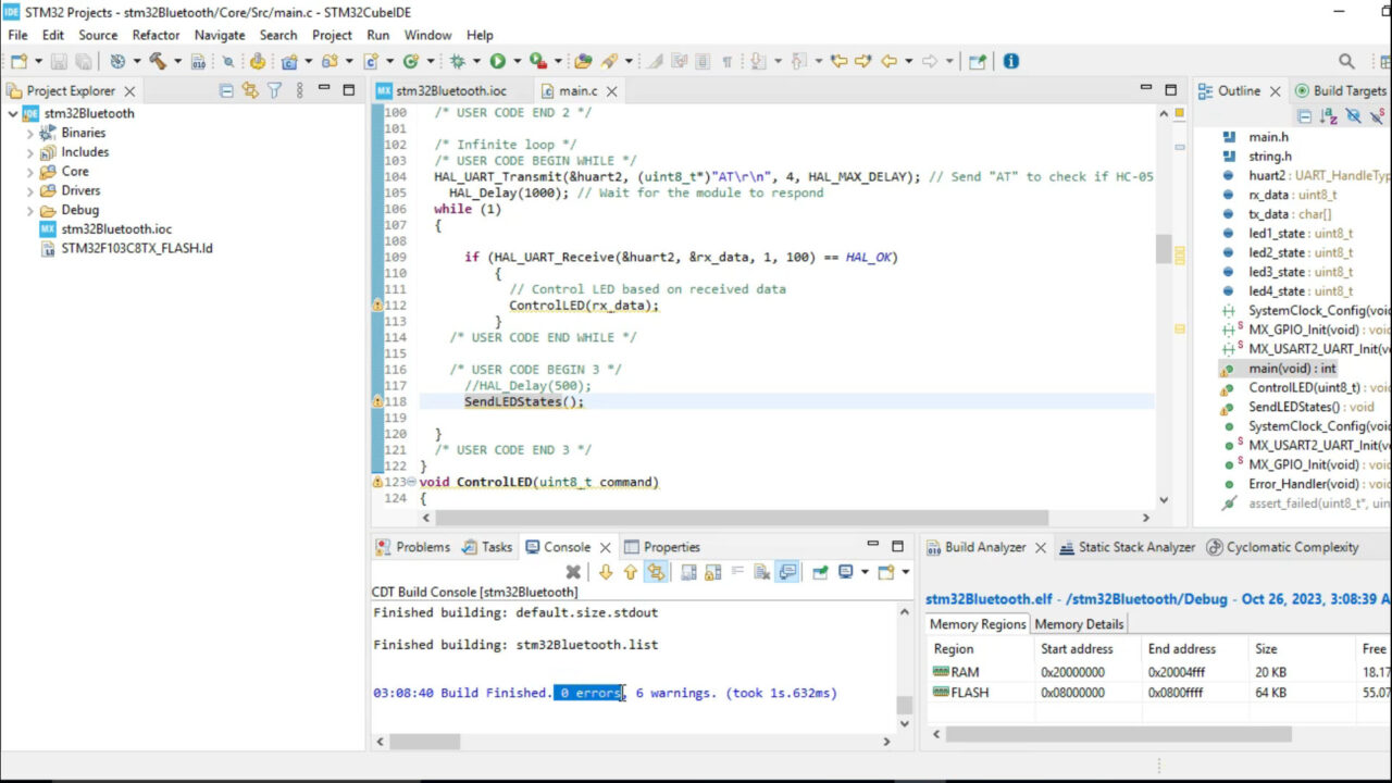
There are no errors and warnings now we can click on the Play button.
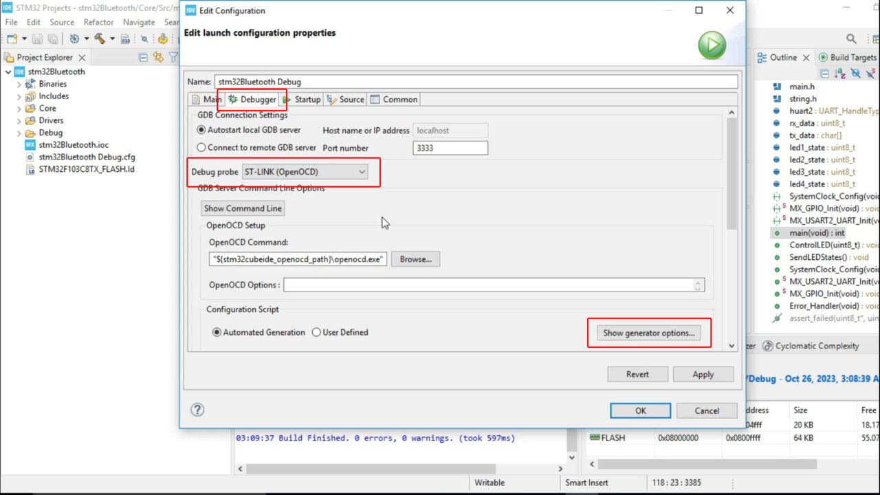
- Click on the Debugger Tab.
- Select ST-LINK.
- Click on Show Generator options and set the Reset Mode to Software system reset
and click the Apply button and then click the OK button. Finally, click the run button and that’s it.
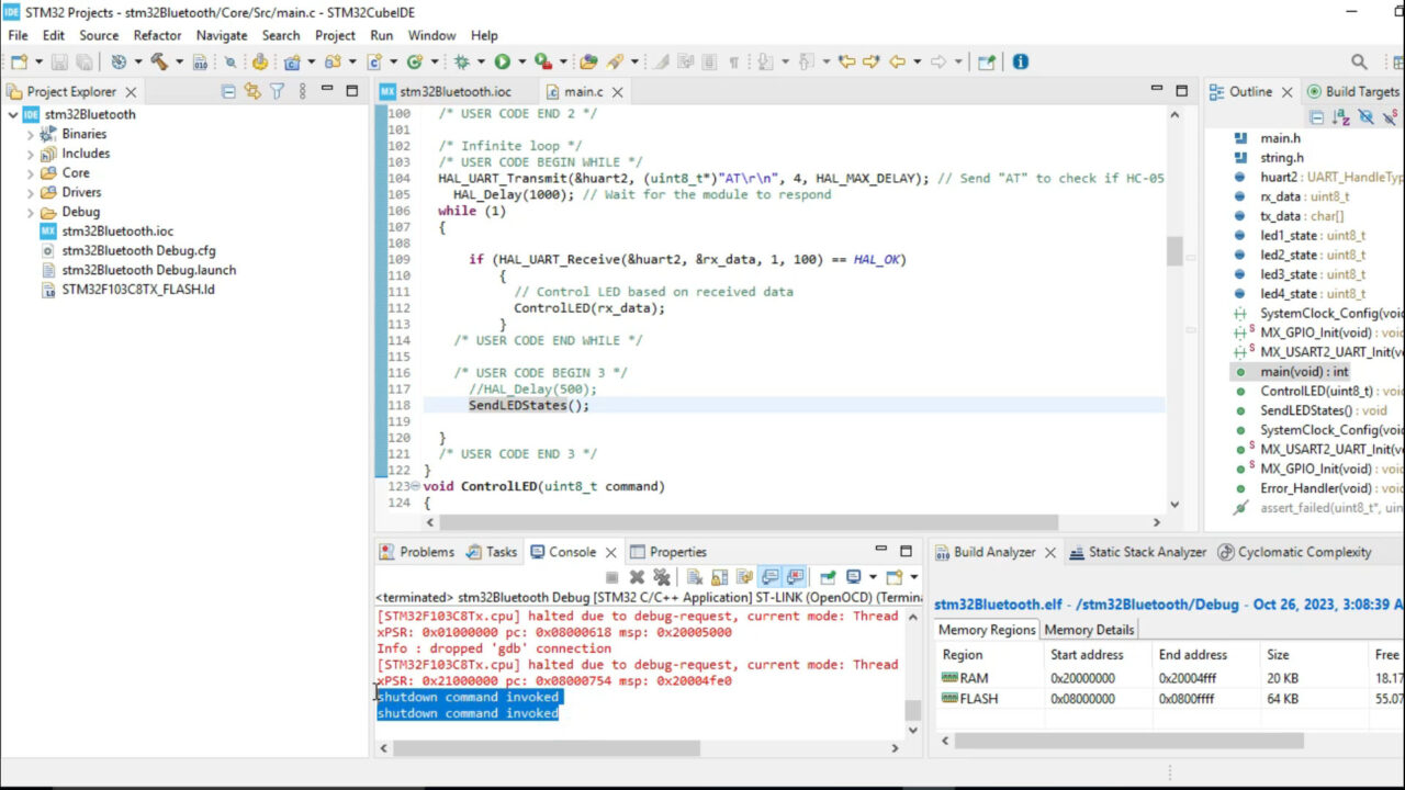
You can see the shutdown command invoked, this means everything is done correctly, now you can unplug your stm32 and plug it again. Connect your android application and start controlling your home appliances.
Read my article on Android App development if you want to design your own android application.
Watch Video Tutorial:

Discover more from Electronic Clinic
Subscribe to get the latest posts sent to your email.
Your needs come first! Purplewaveindia has no agendas, and no loyalties to anyone other than you, our client. Purplewaveindia was established in 2018. And in a short span of 4-years, Purplewaveindia has become one of the prominent players in the Indian Audio Video Manufacturing and Integration Industry.