LoRa SX1278 Arduino Hello World & Sensor Monitoring Projects
Last Updated on September 21, 2024 by Engr. Shahzada Fahad
Table of Contents
LoRa SX1278 Arduino, Description:
LoRa SX1278 Arduino Hello World & Sensor Monitoring Projects–
I have been using different types of short range and log range wireless transceiver modules for quite a long time. Today for the first time I am going to use these Long range and low energy LoRa SX1278 Modules with Arduino. This is a getting started tutorial and I will try my level best to keep things as simple as possible. Initially, I will start with the Hello world example. We will send the Hello world message wirelessly to the receiver LoRa module and then I will modify the same code for monitoring an analog sensor. I will be using a potentiometer as the sensor, which of course you can replace with any other sensor as per your requirement.
Recently I added another article on Arduino and SX1278 Lora based two-way communication system.
Without any further delay, let’s get started!!!
Read my new article on Multiple Lora Nodes communication with the Master Lora Node.
Amazon Links:
Arduino Nano USB-C Type (Recommended)
*Disclosure: These are affiliate links. As an Amazon Associate I earn from qualifying purchases.
Lora SX1278 Module:
The SX1276/77/78/79 transceivers feature the LoRa TM long range modem that provides ultra-long range spread spectrum communication and high interference immunity whilst minimizing current consumption.
Using Semtech’s patented LoRa modulation technique SX1276/77/78/79 can achieve a sensitivity of over -148dBm using a low cost crystal and bill of materials. The high sensitivity combined with the integrated +20 dBm power amplifier yields industry leading link budget making it optimal for any application requiring range or robustness.
LoRa also provides significant advantages in both blocking and selectivity over conventional modulation techniques, solving the traditional design compromise between range, interference immunity and energy consumption.
These devices also support high performance (G)FSK modes for systems including WMBus, IEEE802.15.4g. The SX1276/77/78/79 deliver exceptional phase noise, selectivity, receiver linearity and IIP3 for significantly lower current consumption than competing devices.
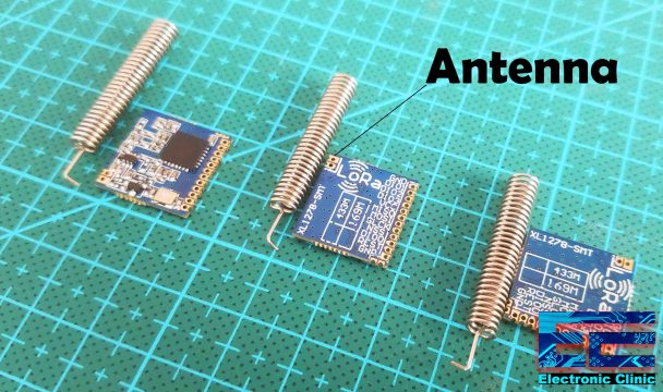
I have got these three LoRa SX1278 Modules, LoRa (Long-Range) is digital wireless data communication IoT technology. LoRa transmits over license-free megahertz radio frequency bands: 169 MHz, 433 MHz (Asia), 868 MHz (Europe) and 915 MHz (North America). LoRa enables very-long-range wireless data transmission. The type of the LoRa modules I am using supports 433MHz. Each LoRa module is also provided with an Antenna which we will need to solder to the boards to increase the wireless communication range.
The supply voltage is 1.8 to 3.7 volts, so it can be used with 3.3 Volts and 5 volts compatible controller boards without any problem. 3.3V compatible boards e.g. ESP8266, ESP32, etc. The operational temperature range is -40 Celsius to +85 Celsius.
It has a total of 12 via’s or holes which are clearly labeled and out of which we will be using only VCC, MISO, MOSI, SLCK, NSS, and GND.
As a beginner you may get scared when you first look at these LoRa modules which has holes as they are very close to each other because you cannot solder regular male or female headers. But no worries at all, you can simply start by soldering jumper wires, which of course will need some soldering practice.
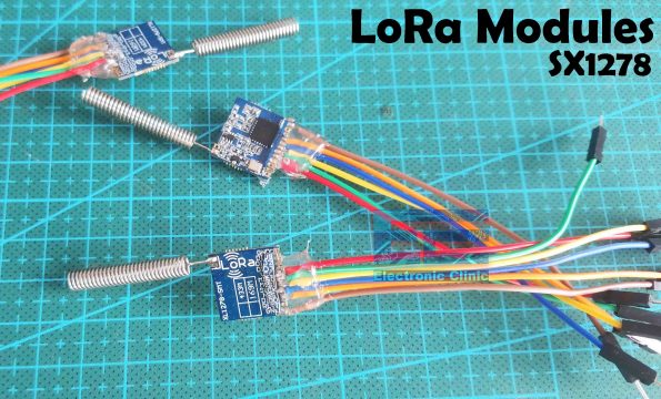
As you can see I soldered the jumpers wires and the antennas. Next, I checked the short circuits using a digital Multimeter, and then to secure the wires I applied the silicon, this will help to keep the wires in place and will also protect the wires from getting disconnected.
LoRa Applications:
When it comes to the applications, you have almost infinite ways of controlling and monitoring things including,
Automated Meter Reading.
Home and Building Automation
Wireless Alarm and Security System
Industrial Monitoring and Control
Long range Irrigation Systems and so on…
But anyways as this is a getting started tutorial, I will stick to the very basics. So, I am going to start with the first example that is the Hello World Example. Let’s take a look at the circuit diagram.
LoRa SX1278 Interfacing with Arduino:
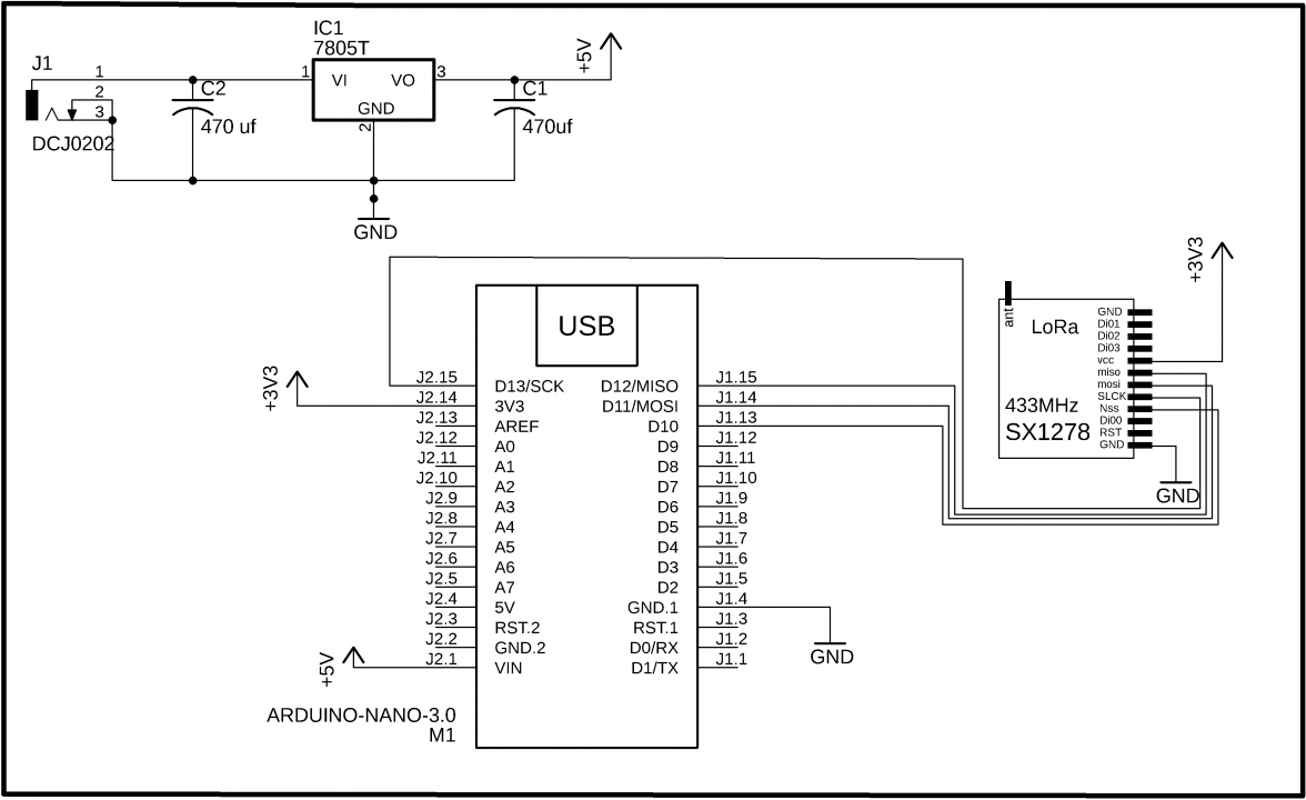
These are the minimal connections which you will need to get started with the LoRa modules. The LoRa SX1278 Module interfacing with the Arduino is very simple. The VCC of the LoRa module is connected with the 3.3V of the Arduino. The MISO Pin of the LoRa module is connected with the Arduino’s pin 12. The MOSI pin is connected with the Arduino’s pin 11. The SCLK pin of the LoRa module is connected with the Arduino’s pin 13. The NSS pin is connected with the Arduino’s pin 10 and the ground pin of the LoRa module is connected with the Arduino’s GND. The same connections we will also need on the receiver side.
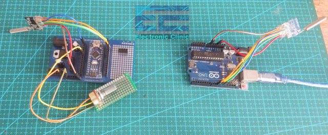
On the top you can see is the 5V regulated power supply based on the 7805 voltage regulator. You will need this power supply if you want to power up your Arduino using an external 12V power supply or a solar panel.
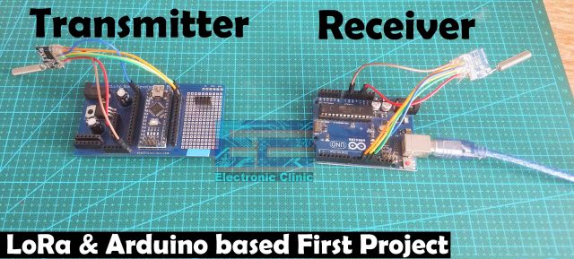
I connected my LoRa modules with the Arduino Nano and Arduino Uno as per the circuit diagram. The codes that I am going to explain can run on both the Arduino boards. So, I am going to use this one as the transmitter and this one as the receiver. So, my hardware is ready and now let’s take a look at the transmitter and receiver programming.
Before, you start the programming, first of all, make sure you download the LoRa library.
LoRa SX1278 Transmitter Programming:
|
1 2 3 4 5 6 7 8 9 10 11 12 13 14 15 16 17 18 19 20 21 22 23 24 25 26 27 28 29 30 31 32 33 |
/* * Transmitter side Code * Module SX1278 // Arduino UNO/NANO Vcc -> 3.3V MISO -> D12 MOSI -> D11 SLCK -> D13 Nss -> D10 GND -> GND */ #include <SPI.h> #include <LoRa.h> void setup() { Serial.begin(9600); while (!Serial); Serial.println("LoRa Sender"); if (!LoRa.begin(433E6)) { // or 915E6, the MHz speed of your module Serial.println("Starting LoRa failed!"); while (1); } } void loop() { String MyMessage = "Hello World, this is Electronic Clinic"; LoRa.beginPacket(); LoRa.print(MyMessage); LoRa.endPacket(); delay(100); } |
As you can see this is such a small code. The only thing that you need to take care of is this frequency (!LoRa.begin(433E6)), as you can see I am using 433MHz, So, if your LoRa module supports another frequency simply change this value.
Inside the Loop() function. I defined a variable MyMessage of the type String, which I am using for storing a message and then using the LoRa.print() function the message is send to other LoRa module on the Receiver side. Now, let’s take a look at the receiver side programming.
LoRa SX1278 Receiver Programming:
|
1 2 3 4 5 6 7 8 9 10 11 12 13 14 15 16 17 18 19 20 21 22 23 24 25 26 27 28 29 30 31 32 33 34 35 36 37 38 39 40 41 42 43 44 45 46 47 |
/* * Receiver Side Code * Module SX1278 // Arduino UNO/NANO Vcc -> 3.3V MISO -> D12 MOSI -> D11 SLCK -> D13 Nss -> D10 GND -> GND */ #include <SPI.h> #include <LoRa.h> String inString = ""; // string to hold incoming charaters String MyMessage = ""; // Holds the complete message void setup() { Serial.begin(9600); while (!Serial); Serial.println("LoRa Receiver"); if (!LoRa.begin(433E6)) { // or 915E6 Serial.println("Starting LoRa failed!"); while (1); } } void loop() { // try to parse packet int packetSize = LoRa.parsePacket(); if (packetSize) { // read packet while (LoRa.available()) { int inChar = LoRa.read(); inString += (char)inChar; MyMessage = inString; } inString = ""; LoRa.packetRssi(); } Serial.println(MyMessage); } |
The receiver side code is also very simple. I defined two variables of the type String. Code inside the setup() function remains exactly the same.
Inside the loop() function we check, if the LoRa module has received data then read from the LoRa module, add each character to inString variable to make a complete message and is then stored in another string variable MyMessage. Finally, we empty the inString variable and then using the serial.println() function, we print the message on the serial monitor. So, that all about the programming.

It’s simply amazing; with just a few lines of code we created this amazing wireless message sending system using Arduino and the low energy Long Range LoRa SX1278 Modules.
Sensor Monitoring using LoRa SX1278 and Arduino:
Sensor monitoring with the LoRa and Arduino is as simple as sending this Hello World message. This hello world example you can use to test your LoRa modules, while the practical use of LoRa may involve monitoring sensors and controlling electrical loads. So, in this next example we are going to make a sensor monitoring system using the Arduino and LoRa module. For now I will do it only for one sensor and then in the upcoming articles I will do it for multiple sensors. So, let’s go ahead and take a look at the transmitter and receiver circuit diagrams.
Sensor Monitoring LoRa Transmitter Circuit:

On the transmitter side I connected a Potentiometer with the analog pin A2 of the Arduino, while everything else remain exactly the same.
Sensor Monitoring LoRa Receiver Circuit:

While on the receiver side nothing is changed.
I connected the Potentiometer as per the circuit diagram. My transmitter and receiver circuits are ready. Now, let’s take a look at the Transmitter and receiver programming.
Sensor Monitoring LoRa Transmitter Code:
|
1 2 3 4 5 6 7 8 9 10 11 12 13 14 15 16 17 18 19 20 21 22 23 24 25 26 27 28 29 30 31 32 33 34 |
/* * Sensor Monitoring using Arduino and LoRa SX1278 Module, transmitter code Module SX1278 // Arduino UNO/NANO Vcc -> 3.3V MISO -> D12 MOSI -> D11 SLCK -> D13 Nss -> D10 GND -> GND */ #include <SPI.h> #include <LoRa.h> int pot = A2; void setup() { Serial.begin(9600); pinMode(pot,INPUT); while (!Serial); Serial.println("LoRa Sender"); if (!LoRa.begin(433E6)) { // or 915E6, the MHz speed of your module Serial.println("Starting LoRa failed!"); while (1); } } void loop() { int val = map(analogRead(pot),0,1024,0,255); LoRa.beginPacket(); LoRa.print(val); LoRa.endPacket(); delay(50); } |
In the transmitter code I did only two changes. I defined a pin for the Potentiometer which is connected with the Analog pin A2.
Inside the loop() function, I am simply reading the Potentiometer and stored the value in variable val. You can see I am using the map function. So, the value which is stored in the variable Val is the mapped value and finally, using the LoRa.print() function the Potentiometer value is send to the Receiver side. Now, let’s take a look at the receiver side programming.
Sensor Monitoring LoRa Receiver Code:
|
1 2 3 4 5 6 7 8 9 10 11 12 13 14 15 16 17 18 19 20 21 22 23 24 25 26 27 28 29 30 31 32 33 34 35 36 37 38 39 40 41 42 43 44 45 46 47 |
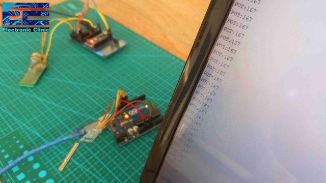
/* * Sensor Monitoring using Arduino and LoRa SX1278 Module, receiver code * Module SX1278 // Arduino UNO/NANO Vcc -> 3.3V MISO -> D12 MOSI -> D11 SLCK -> D13 Nss -> D10 GND -> GND */ #include <SPI.h> #include <LoRa.h> String inString = ""; // string to hold input int val = 0; void setup() { Serial.begin(9600); while (!Serial); Serial.println("LoRa Receiver"); if (!LoRa.begin(433E6)) { // or 915E6 Serial.println("Starting LoRa failed!"); while (1); } } void loop() { // try to parse packet int packetSize = LoRa.parsePacket(); if (packetSize) { // read packet while (LoRa.available()) { int inChar = LoRa.read(); inString += (char)inChar; val = inString.toInt(); } inString = ""; LoRa.packetRssi(); } Serial.print("POT:"); Serial.println(val); } |
On the receiver side, I defined a variable for storing the Potentiometer value. Maximum of the code remains exactly the same, I added this one more instruction that converts the string value into an integer value. Finally, these instructions are used to send the Potentiometer values to the serial monitor. So, that’s all about the transmitter and receiver programming.
In my upcoming videos and articles, I will display the sensor value on the Oled display module, I will also explain how to monitor multiple sensors, how to communicate with multiple Lora nodes, how to request data from a particular node, how to make a Lora Gateway, and so on. Consider subscribing if you don’t want to miss any of my upcoming videos.
Watch Video Tutorial:
Discover more from Electronic Clinic
Subscribe to get the latest posts sent to your email.


Thanks, that was so easy to follow and everything worked straight away!
Hallo where can i find the downloads ?
Hello. Your explanation is fine and everything works for me immediately. Thank you. My question: Can the lora module also be switched on and off in software? This is due to a sleep mode. Thank you for a response.
Hi, i got “Starting LoRa failed”. i use Arduino Uno and tesing the Receiver first and got that error.
Hi,
i have bought this module and tested with esp32, but am not getting any response from LORA module,
i have checked the wiring properly. still no use
can you please help
Thanks in advance
Hi, I made this and it works but if I move anything at all the receiver output freezes. Also is it possible to make a remote control with this?