Multiple Lora Nodes Communication with the Master Lora Node
Last Updated on September 21, 2024 by Engr. Shahzada Fahad
Table of Contents
Multiple Lora Nodes, Description:
Multiple Lora Nodes Communication with the Master Lora Node– Before, I am going to explain how to connect multiple Lora Nodes with the Master Lora Node, first I very quick recap on what I did in my previous three tutorials based on the Arduino and the SX1278 Lora transceiver modules.
In my first tutorial, which was based on the Arduino and SX1278 Lora transceiver modules, I explained the maximum basic things including the SX1278 Lora module Pinout, technical specifications, and it’s interfacing with the Arduino. I demonstrated two beginners level projects. The Hello World project in which I was simply sending the Hello World message wirelessly to the receiver Lora module and then in the next example I modified the same program and converted it into a sensor monitoring system.
In my 2nd tutorial, I explained how to make a long range wireless two way communication system using the same 433Mhz SX1278 Lora Transceiver modules. In this project, I was simply sending the Potentiometer value from the Master Node to the Slave Node and then I was printing its value on the i2c supported Oled display module. While on the other side I used a push button and I was able to send the button status. You can use multiple buttons and control multiple things as per your requirement.
In my 3rd tutorial, I explained how to monitor multiple analog and digital sensors connected to the Lora Node 1. For demonstration purposes, I used a potentiometer, Flame Sensor, and digital LDR Sensor board. This system was quite responsive and the communication was too fast, with such fast wireless communication you can control RC planes, Robots, servos, DC motors, etc. Next, I checked the Flame sensor which did its job by detecting the fire and I was able to send the Flame sensor values wirelessly to the Master Node along with the other sensors values. You can modify this code to make a fire alarm system. Anyways, finally, I tested the LDR Sensor board and I used it for the day and night detection. While performing the tests I also explained how to change the sensitivity of the LDR module. Personally, I highly recommend you should read this article because from this article you will learn how to send all the sensors values in one message and then how to split the sensors values and store them in separate variables. So, that’s all about my previous work on the SX1278 Lora Module.
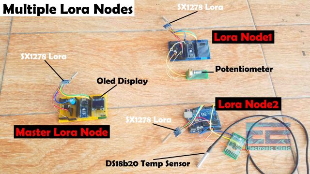
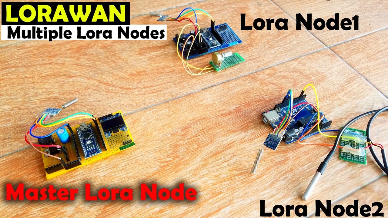
In today’s tutorial, you will learn how to perform two-way communication with multiple Lora nodes. Right now I have only three Lora modules, so, I am using one as the Master Lora node and the other two as the Lora end devices. To the master Lora Node, an i2c supported Oled display module is connected which I will be using for displaying the data received from the other two Lora Nodes. To the Lora Node1, a potentiometer is connected which I am going to use as the sensor. You can replace this sensor with any other sensor of your choice. To the Lora Node2, DS18b20 waterproof one-wire digital temperature sensor is connected.
So, you can see to the Arduino Lora nodes or Lora end devices two different sensors are connected, we will be sending its values to the master Lora Node along with the Node1 or Node2 information. You can add more Lora Nodes with the same or different sensors connected. So, let’s go ahead and check how this system works.

The Master Lora Node, first, sends a request to the Lora Node1, for this I created a timer using the millis() function. So, for the first 5 seconds, the Master Lora node sends multiple requests to the Lora Node1 and receives data from the Node1, this time duration can be changed in the programming. But it’s good to give it enough time so that the master node can get multiple replies from the Lora end device. As you can clearly see for the first 5 seconds it receives data from the Node1 and then for the other 5 seconds it receives data from the Lora Node2 to which the DS18b20 Temperature sensor is connected.
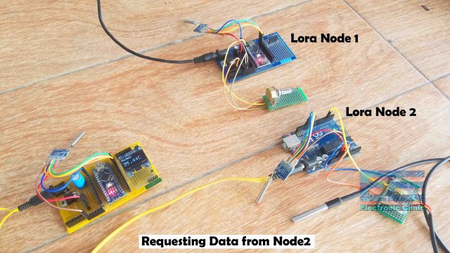
The Node name is also printed on the Oled display module so there is no confusion at all. As this entire system is based on two way communication so you can also send commands to remotely control devices connected with the Lora end devices.

I also added the emergency alarm message which is sent when the temperature exceeds a predefined value which In my case is 40 degrees Celsius. Anyways, you can also send messages to the Master Lora Node without waiting for the request. Now, with this project, you can implement a complete LORAWAN and you can covert this Master Node into a Lora Gateway and this way you can send your sensors data to the IoT platform like Blynk, Thingspeak, Arduino IoT Cloud, Ubidots, etc. It’s totally up to you how you modify this project and for what purpose you want to use it. You can also let me know in a comment. Now, you have got an idea of what you are going to learn after reading this article. Without any further delay, let’s get started!!!
Amazon Links:
Arduino Nano USB-C Type (Recommended)
SSD1306 128×64 Oled i2c display Module
DS18b20 Waterproof One-Wire digital Temperature Sensor
*Disclosure: These are affiliate links. As an Amazon Associate I earn from qualifying purchases.
Arduino Master Lora Node:

This is the circuit diagram of the Master Lora Node, the connection of the SX1278 Lora module remains exactly the same as explained in my previous two tutorials. This time I added the SSD1306 I2C supported Oled display Module. The VCC and GND pins of the SSD1306 Oled display module are connected with the Arduino’s 3.3V and GND pins. The SDA and SCL pins of the Oled display module are connected with the Arduino’s I2C pins A4 and A5.
The VCC of the LoRa module is connected with the 3.3V of the Arduino. The MISO Pin of the LoRa module is connected with the Arduino’s pin 12. The MOSI pin is connected with the Arduino’s pin 11. The SCLK pin of the LoRa module is connected with the Arduino’s pin 13. The NSS pin is connected with the Arduino’s pin 10 and the ground pin of the LoRa module is connected with the Arduino’s GND.
On the top left side you can see the 5V regulated power supply based on the LM7805 Voltage regulator.
Lora Node 1 Circuit:

This is the circuit diagram of the Lora Node1. The connection of the SX1278 Lora module remains exactly the same. The middle leg of the potentiometer is connected with the Analog pin A2 while the other two legs of the potentiometer are connected with the Arduino’s 5V and GND.
Lora Node 2 Circuit:

This is the circuit diagram of the Lora Node2. The connection of the SX1278 Lora module remains exactly the same. The DS18b20 one wire digital temperature sensor Data wire is connected with the digital pin 3 of the Arduino. While the VCC and GND wires of the DS18b20 temperature sensor are connected with the Arduino’s 5V and GND. Don’t forget to add this 330 ohm resistor between the VCC and GND wires of the DS18b20 temperature sensor.
Arduino Lora Nodes Programming:
Before, you start the programming first of all; make sure you download all the necessary.
As this project is based on multiple Lora Nodes, so each Lora Node has its own code. As in this project we have a total of three Arduino based Lora Nodes, So, we have three codes. So, let’s first start with the Master Lora Node.
Arduino Master Lora Node, Code:
|
1 2 3 4 5 6 7 8 9 10 11 12 13 14 15 16 17 18 19 20 21 22 23 24 25 26 27 28 29 30 31 32 33 34 35 36 37 38 39 40 41 42 43 44 45 46 47 48 49 50 51 52 53 54 55 56 57 58 59 60 61 62 63 64 65 66 67 68 69 70 71 72 73 74 75 76 77 78 79 80 81 82 83 84 85 86 87 88 89 90 91 92 93 94 95 96 97 98 99 100 101 102 103 104 105 106 107 108 109 110 111 112 113 114 115 116 117 118 119 120 121 122 123 124 125 126 127 128 129 130 131 132 133 134 135 136 137 138 139 140 141 142 143 144 145 146 147 148 149 150 151 152 153 154 155 156 157 158 159 |
/* Master Lora Node https://www.electroniclinic.com/ */ #include <SPI.h> // include libraries #include <LoRa.h> #include <Adafruit_GFX.h> #include <Adafruit_SSD1306.h> #define SCREEN_WIDTH 128 // OLED display width, in pixels #define SCREEN_HEIGHT 64 // OLED display height, in pixels // Declaration for an SSD1306 display connected to I2C (SDA, SCL pins) #define OLED_RESET -1 // Reset pin # (or -1 if sharing Arduino reset pin) Adafruit_SSD1306 display(SCREEN_WIDTH, SCREEN_HEIGHT, &Wire, OLED_RESET); byte MasterNode = 0xFF; byte Node1 = 0xBB; byte Node2 = 0xCC; String SenderNode = ""; String outgoing; // outgoing message byte msgCount = 0; // count of outgoing messages // Tracks the time since last event fired unsigned long previousMillis=0; unsigned long int previoussecs = 0; unsigned long int currentsecs = 0; unsigned long currentMillis = 0; int interval= 1 ; // updated every 1 second int Secs = 0; void setup() { Serial.begin(9600); // initialize serial display.begin(SSD1306_SWITCHCAPVCC, 0x3C); delay(2000); display.clearDisplay(); display.setTextColor(WHITE); if (!LoRa.begin(433E6)) { // initialize ratio at 915 MHz Serial.println("LoRa init failed. Check your connections."); while (true); // if failed, do nothing } // Serial.println("LoRa init succeeded."); } void loop() { currentMillis = millis(); currentsecs = currentMillis / 1000; if ((unsigned long)(currentsecs - previoussecs) >= interval) { Secs = Secs + 1; //Serial.println(Secs); if ( Secs >= 11 ) { Secs = 0; } if ( (Secs >= 1) && (Secs <= 5) ) { String message = "34"; sendMessage(message,MasterNode, Node1); } if ( (Secs >= 6 ) && (Secs <= 10)) { String message = "55"; sendMessage(message,MasterNode, Node2); } previoussecs = currentsecs; } // parse for a packet, and call onReceive with the result: onReceive(LoRa.parsePacket()); } void sendMessage(String outgoing, byte MasterNode, byte otherNode) { LoRa.beginPacket(); // start packet LoRa.write(otherNode); // add destination address LoRa.write(MasterNode); // add sender address LoRa.write(msgCount); // add message ID LoRa.write(outgoing.length()); // add payload length LoRa.print(outgoing); // add payload LoRa.endPacket(); // finish packet and send it msgCount++; // increment message ID } void onReceive(int packetSize) { if (packetSize == 0) return; // if there's no packet, return // read packet header bytes: int recipient = LoRa.read(); // recipient address byte sender = LoRa.read(); // sender address if( sender == 0XBB ) SenderNode = "Node1:"; if( sender == 0XCC ) SenderNode = "Node2:"; byte incomingMsgId = LoRa.read(); // incoming msg ID byte incomingLength = LoRa.read(); // incoming msg length String incoming = ""; while (LoRa.available()) { incoming += (char)LoRa.read(); } if (incomingLength != incoming.length()) { // check length for error //Serial.println("error: message length does not match length"); ; return; // skip rest of function } // if the recipient isn't this device or broadcast, if (recipient != Node1 && recipient != MasterNode) { // Serial.println("This message is not for me."); ; return; // skip rest of function } // if message is for this device, or broadcast, print details: //Serial.println("Received from: 0x" + String(sender, HEX)); //Serial.println("Sent to: 0x" + String(recipient, HEX)); //Serial.println("Message ID: " + String(incomingMsgId)); // Serial.println("Message length: " + String(incomingLength)); // Serial.println("Message: " + incoming); //Serial.println("RSSI: " + String(LoRa.packetRssi())); // Serial.println("Snr: " + String(LoRa.packetSnr())); // Serial.println(); //clear display display.clearDisplay(); display.setTextSize(2); display.setCursor(0,0); display.print(SenderNode); if( sender == 0XBB ) { display.setTextSize(3); display.setCursor(0, 28); display.print(incoming + "Pot"); } if( sender == 0XCC ) { display.setTextSize(3); display.setCursor(0, 28); display.print(incoming + "C"); } display.display(); } |
Arduino Lora Node1, Code:
|
1 2 3 4 5 6 7 8 9 10 11 12 13 14 15 16 17 18 19 20 21 22 23 24 25 26 27 28 29 30 31 32 33 34 35 36 37 38 39 40 41 42 43 44 45 46 47 48 49 50 51 52 53 54 55 56 57 58 59 60 61 62 63 64 65 66 67 68 69 70 71 72 73 74 75 76 77 78 79 80 81 82 83 84 85 86 87 88 89 |
/* Lora Node1 https://www.electroniclinic.com/ */ #include <SPI.h> // include libraries #include <LoRa.h> int POT = A2; String outgoing; // outgoing message byte msgCount = 0; // count of outgoing messages byte MasterNode = 0xFF; byte Node1 = 0xBB; void setup() { Serial.begin(9600); // initialize serial pinMode(POT, INPUT); while (!Serial); Serial.println("LoRa Duplex"); if (!LoRa.begin(433E6)) { // initialize ratio at 915 MHz Serial.println("LoRa init failed. Check your connections."); while (true); // if failed, do nothing } Serial.println("LoRa init succeeded."); } void loop() { // parse for a packet, and call onReceive with the result: onReceive(LoRa.parsePacket()); } void sendMessage(String outgoing, byte MasterNode, byte otherNode) { LoRa.beginPacket(); // start packet LoRa.write(MasterNode); // add destination address LoRa.write(Node1); // add sender address LoRa.write(msgCount); // add message ID LoRa.write(outgoing.length()); // add payload length LoRa.print(outgoing); // add payload LoRa.endPacket(); // finish packet and send it msgCount++; // increment message ID } void onReceive(int packetSize) { if (packetSize == 0) return; // if there's no packet, return // read packet header bytes: int recipient = LoRa.read(); // recipient address byte sender = LoRa.read(); // sender address byte incomingMsgId = LoRa.read(); // incoming msg ID byte incomingLength = LoRa.read(); // incoming msg length String incoming = ""; while (LoRa.available()) { incoming += (char)LoRa.read(); } if (incomingLength != incoming.length()) { // check length for error // Serial.println("error: message length does not match length"); ; return; // skip rest of function } // if the recipient isn't this device or broadcast, if (recipient != Node1 && recipient != MasterNode) { //Serial.println("This message is not for me."); ; return; // skip rest of function } Serial.println(incoming); int Val = incoming.toInt(); if(Val == 34) { String message = String(analogRead(POT)); sendMessage(message,MasterNode,Node1); delay(100); } } |
Arduino Lora Node2, Code:
|
1 2 3 4 5 6 7 8 9 10 11 12 13 14 15 16 17 18 19 20 21 22 23 24 25 26 27 28 29 30 31 32 33 34 35 36 37 38 39 40 41 42 43 44 45 46 47 48 49 50 51 52 53 54 55 56 57 58 59 60 61 62 63 64 65 66 67 68 69 70 71 72 73 74 75 76 77 78 79 80 81 82 83 84 85 86 87 88 89 90 91 92 93 94 95 96 97 98 99 100 101 102 103 104 |
/* Lora Node2 https://www.electroniclinic.com/ */ #include <SPI.h> // include libraries #include <LoRa.h> #include <OneWire.h> #include <DallasTemperature.h> #define ONE_WIRE_BUS 3 OneWire oneWire(ONE_WIRE_BUS); DallasTemperature sensors(&oneWire); float Celcius=0; float Fahrenheit=0; String outgoing; // outgoing message byte msgCount = 0; // count of outgoing messages byte MasterNode = 0xFF; byte Node2 = 0xCC; void setup() { Serial.begin(9600); // initialize serial sensors.begin(); if (!LoRa.begin(433E6)) { // initialize ratio at 915 MHz Serial.println("LoRa init failed. Check your connections."); while (true); // if failed, do nothing } //Serial.println("LoRa init succeeded."); } void loop() { // parse for a packet, and call onReceive with the result: onReceive(LoRa.parsePacket()); } void sendMessage(String outgoing, byte MasterNode, byte otherNode) { LoRa.beginPacket(); // start packet LoRa.write(MasterNode); // add destination address LoRa.write(Node2); // add sender address LoRa.write(msgCount); // add message ID LoRa.write(outgoing.length()); // add payload length LoRa.print(outgoing); // add payload LoRa.endPacket(); // finish packet and send it msgCount++; // increment message ID } void onReceive(int packetSize) { if (packetSize == 0) return; // if there's no packet, return // read packet header bytes: int recipient = LoRa.read(); // recipient address byte sender = LoRa.read(); // sender address byte incomingMsgId = LoRa.read(); // incoming msg ID byte incomingLength = LoRa.read(); // incoming msg length String incoming = ""; while (LoRa.available()) { incoming += (char)LoRa.read(); } if (incomingLength != incoming.length()) { // check length for error // Serial.println("error: message length does not match length"); ; return; // skip rest of function } // if the recipient isn't this device or broadcast, if (recipient != Node2 && recipient != MasterNode) { //Serial.println("This message is not for me."); ; return; // skip rest of function } Serial.println(incoming); int Val = incoming.toInt(); if(Val == 55) { myTemp(); String message = String(Celcius); sendMessage(message,MasterNode,Node2); delay(100); } } void myTemp() { sensors.requestTemperatures(); Celcius=sensors.getTempCByIndex(0); Fahrenheit=sensors.toFahrenheit(Celcius); if ( Celcius > 40 ) { String message = "Warning.."; sendMessage(message,MasterNode,Node2); } } |
Lora Nodes Codes Explanation:
|
1 2 3 4 5 6 7 8 9 |
#define SCREEN_WIDTH 128 // OLED display width, in pixels #define SCREEN_HEIGHT 64 // OLED display height, in pixels // Declaration for an SSD1306 display connected to I2C (SDA, SCL pins) #define OLED_RESET -1 // Reset pin # (or -1 if sharing Arduino reset pin) Adafruit_SSD1306 display(SCREEN_WIDTH, SCREEN_HEIGHT, &Wire, OLED_RESET); |
This is the code for the SSD1306 i2c supported Oled display module.
|
1 2 3 4 5 |
byte MasterNode = 0xFF; byte Node1 = 0xBB; byte Node2 = 0xCC; |
Next, I assigned addresses to all the three nodes. The address of the Master Lora node is 0xFF, Address of the Lora Node1 is 0xBB, and address of the Lora Node2 is 0xCC.
|
1 2 3 4 5 6 7 8 9 10 11 12 13 |
// Tracks the time since last event fired unsigned long previousMillis=0; unsigned long int previoussecs = 0; unsigned long int currentsecs = 0; unsigned long currentMillis = 0; int interval= 1 ; // updated every 1 second int Secs = 0; |
Next, I defined some variables for counting the seconds.
|
1 2 3 4 5 6 7 8 9 10 11 12 13 14 15 16 17 18 19 20 21 22 23 24 25 26 27 28 29 30 31 32 33 34 35 36 37 38 39 40 41 42 43 44 45 46 47 48 49 50 51 52 53 54 55 56 57 58 59 60 61 62 63 |
void loop() { currentMillis = millis(); currentsecs = currentMillis / 1000; if ((unsigned long)(currentsecs - previoussecs) >= interval) { Secs = Secs + 1; //Serial.println(Secs); if ( Secs >= 11 ) { Secs = 0; } if ( (Secs >= 1) && (Secs <= 5) ) { String message = "34"; sendMessage(message,MasterNode, Node1); } if ( (Secs >= 6 ) && (Secs <= 10)) { String message = "55"; sendMessage(message,MasterNode, Node2); } previoussecs = currentsecs; } // parse for a packet, and call onReceive with the result: onReceive(LoRa.parsePacket()); } |
Inside the loop() function, we count the seconds using the millis() function. If the seconds are greater than or equal to 11 then again start counting the seconds from 0. The next condition sends the command 34 to the Lora Node 1 for 5 seconds. This means the master node will receive data from the Lora Node1 for 5 seconds. So, during these 5 seconds multiple requests are send to the Lora Node1. The next condition sends the command 55 to the Lora Node 2 for 5 seconds. This way you can request data from multiple Lora nodes.
|
1 2 3 4 5 6 7 8 9 10 11 12 13 |
// read packet header bytes: int recipient = LoRa.read(); // recipient address byte sender = LoRa.read(); // sender address if( sender == 0XBB ) SenderNode = "Node1:"; if( sender == 0XCC ) SenderNode = "Node2:"; |
Next, we check if the received data is coming from Node1 or Node2 and then accordingly we store Node1 or Node2 in the variable SenderNode which later we will print on the Oled display module. Rest of the code is about reading from the Lora module and then printing the data on the Oled display module which I have already explained my previous tutorial. Now, let’s take a look at the Lora Node1.
|
1 |
int POT = A2; |
The potentiometer is connected to the analog pin A2.
|
1 2 3 |
byte MasterNode = 0xFF; byte Node1 = 0xBB; |
Next, I defined addresses of Master Node and Node1.
|
1 2 3 4 5 6 7 8 9 10 11 12 13 |
int Val = incoming.toInt(); if(Val == 34) { String message = String(analogRead(POT)); sendMessage(message,MasterNode,Node1); delay(100); } |
We check if the node1 has received the command 34 then we read the potentiometer and send the value to the Master node. Now, let’s take a look at the Node2 programming.
|
1 2 3 |
#include <OneWire.h> #include <DallasTemperature.h> |
You will need these two libraries for the DS18b20 temperature sensor.
|
1 |
#define ONE_WIRE_BUS 3 |
I defined a pin to which the temperature sensor is connected.
|
1 2 3 |
byte MasterNode = 0xFF; byte Node2 = 0xCC; |
Next, I defined the addresses of the Master Node and the Node2.
|
1 2 3 4 5 6 7 8 9 10 11 12 13 14 15 |
int Val = incoming.toInt(); if(Val == 55) { myTemp(); String message = String(Celcius); sendMessage(message,MasterNode,Node2); delay(100); } |
If the node 2 has received the command 55 then we read the temperature and send it to the master Lora Node.
|
1 2 3 4 5 6 7 8 9 10 11 12 13 14 15 16 17 18 19 20 21 22 23 24 25 26 27 |
void myTemp() { sensors.requestTemperatures(); Celcius=sensors.getTempCByIndex(0); Fahrenheit=sensors.toFahrenheit(Celcius); if ( Celcius > 40 ) { String message = "Warning.."; sendMessage(message,MasterNode,Node2); } } |
If the temperature has exceeded the predefined value then the message Warning.. is send to the Master Node. So, that’s all about the programming.
Watch Video Tutorial:
Discover more from Electronic Clinic
Subscribe to get the latest posts sent to your email.


This looks first rate. Just what I’m looking for. I’m hoping to adapt it for ultrasonic sensors (HS04) to measure the water depth in our four water tanks! I think I can also connect the receiver node to an ESP8266 and read results on my phone.
Very informative video & topic.
One question. How to communicate Master to master using same loRA module. Since each master doesnt know when to initiate communication. How we can resolve this?
I have a question regarding adding additional nodes. It has to do with naming conventions. For example if I were to add a third node would the address be 0xDD? Also node one is also named “34” and node two “55” were these chosen arbitrarily? What would node three be named? 66? Thanks again for developing this..
I don’t know if you’re still monitoring this… I’ve got the three nodes up and running, but I’m continually getting an error: “message length does not match length.” I’ve tried it with both nodes 1 and 2 running and with them individually. Any ideas?