Multiple Sensors Monitoring with Arduino Lora Nodes, SX1278 Lora
Last Updated on September 21, 2024 by Engr. Shahzada Fahad
Table of Contents
Multiple Sensors Monitoring, Description:
Multiple Sensors Monitoring with Arduino Lora Nodes- Before I am going to explain how to monitor multiple sensors using Arduino and Lora SX1278 Transceiver modules, first, a very quick recap on what I did in my last two tutorials. In my first tutorial which was based on the Arduino and SX1278 Lora transceiver modules, I explained the maximum basic things including the SX1278 Lora module Pinout, technical specifications, and its interfacing with the Arduino. I demonstrated two beginners level projects. In the Hello World project in which I was simply sending the Hello World message wirelessly to the receiver Lora module and then in the next example I modified the same program and converted it into a sensor monitoring system.
In my 2nd tutorial, I explained how to make a long range wireless two way communication system using the same 433Mhz SX1278 Lora Transceiver modules. In this project, I was simply sending the Potentiometer value from the Master Node to the Slave Node and then I was printing its value on the i2c supported Oled display module. If you remember I had told you that we can replace the potentiometer with other analog and digital sensors. So, today I will do it. Along with the Potentiometer I will also use a Flame Sensor for the fire detection and an LDR Sensor for day and night detection. So, if you are a beginner then I highly recommend you should first read my previous two tutorials on the Arduino and SX1278 Lora modules and then you can resume from here.
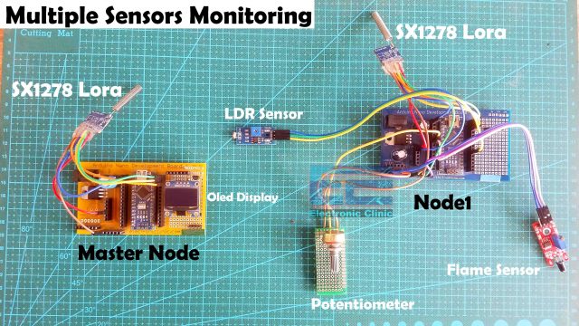
In today’s article, you will learn how to monitor multiple Sensors using Arduino and Long Range 433Mhz SX1278 Lora Transceiver modules. To the Master Lora Node an Oled display module is connected which of course we will be using for printing the sensors values and messages.
To the Lora Node1, A Potentiometer, Flame Sensor, and digital LDR Sensors are connected. Let’s go ahead and start with the Potentiometer.
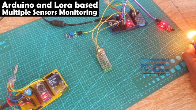
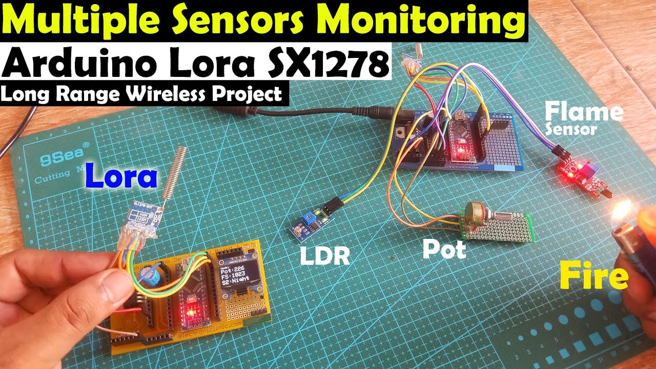
Initially, I started with the Potentiometer, by rotating the knob of the Potentiometer I could see change in the value on the Oled display module. The value next to the Pot is the Potentiometer value. The system is quite responsive and the data is transmitted very fast, now, with this potentiometer, you can control a servo, a stepper motor, dc motor, and so on. The next value on the Oled display is the Flame Sensor value, right now you can see the value of the Flame Sensor is 56 as the sensor is detecting the fire. When there is no fire then you will see a value greater than 1000. This sensor should only be used inside or in dark place otherwise you will get wrong values as the ambient light has the infrared. I have been using this flame sensor and it’s good for beginners, you can see a change in the value when the Flame Sensor detects the fire.
Finally, I started testing the digital LDR Sensor. Current on the Oled display you can see Day is written, as there is no shadow on the LDR sensor, currently I have adjusted the Pot on the LDR sensor board and it can detect shadows. This LDR Sensor board is designed in a way that it gives only two outputs 1 or 0. So, depending on these two output states we can decide if it’s the daytime or the night time and as you can clearly see on the Oled display module, when there is no shadow on the LDR it displays day.
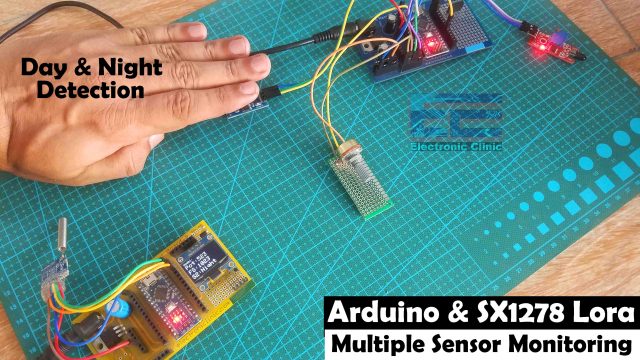
When there is a shadow then it displays night. You can adjust the sensitivity of the sensor with the help of the potentiometer, this way it will only generate the signal when there is absolutely no light at all. I checked this whole project repeatedly and it was working just great. If you want to further improve the user experience then you can add a watchdog timer in the programming, this way when the Arduino hangs, the watchdog timer will automatically reset the Arduino.
So, how it’s working? The Arduino reads all the sensors, creates a message consisting of the sensors values which are separated with commas. The final message is then send to the Master Lora Node where the message is split using Comma as the delimiter. The separated sensor values are then converted back into integer values. Some conditions are implemented and then finally, the sensors values are printed on the Oled display Module.
Now, you have got an idea of what you are going to learn after watching this video. Without any further delay, let’s get started!!!
Read my new article on Multiple Lora Nodes communication with the Master Lora Node.
Amazon Links:
Arduino Nano USB-C Type (Recommended)
SSD1306 128×64 Oled i2c display Module
*Disclosure: These are affiliate links. As an Amazon Associate I earn from qualifying purchases.
Arduino Master Lora Node Circuit:
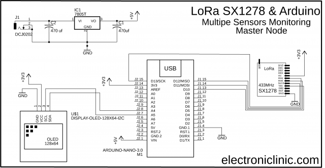
This is the circuit diagram of the Master Lora Node, the connection of the SX1278 Lora module remains exactly the same as explained in my previous two tutorials. This time I added the SSD1306 I2C supported Oled display Module. The VCC and GND pins of the SSD1306 Oled display module are connected with the Arduino’s 3.3V and GND pins. The SDA and SCL pins of the Oled display module are connected with the Arduino’s I2C pins A4 and A5.
The VCC of the LoRa module is connected with the 3.3V of the Arduino. The MISO Pin of the LoRa module is connected with the Arduino’s pin 12. The MOSI pin is connected with the Arduino’s pin 11. The SCLK pin of the LoRa module is connected with the Arduino’s pin 13. The NSS pin is connected with the Arduino’s pin 10 and the ground pin of the LoRa module is connected with the Arduino’s GND.
Arduino Lora Node 1 Circuit:
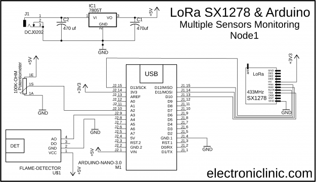
This is the circuit diagram of the Lora Node 1. The connection of the SX1278 Lora module remains exactly the same. The Potentiometer is connected with the Analog pin A2, the flame sensor is connected with the Analog pin A3, and the output of the LDR circuit is connected with the digital pin 3 of the Arduino.
Multiple Sensors Monitoring Programming:
Before, you start the programming first of all; make sure you download all the necessary.
Arduino Lora Node 1 Programming:
|
1 2 3 4 5 6 7 8 9 10 11 12 13 14 15 16 17 18 19 20 21 22 23 24 25 26 27 28 29 30 31 32 33 34 35 36 37 38 39 40 41 42 43 44 45 46 47 48 49 50 51 52 53 54 55 56 57 58 59 60 61 62 63 |
/* Lora Node 1 */ #include <SPI.h> // include libraries #include <LoRa.h> int POT = A2; // potentiometer int FlameSensor = A3; // Flame Sensor int LDRSensor = 3; // digital LDR Sensor String outgoing; // outgoing message byte msgCount = 0; // count of outgoing messages byte MasterNode = 0xFF; byte Node1 = 0xBB; int Sensor1 = 0; // Potentiometer int Sensor2 = 0; // Flame Sensor int Sensor3 = 0; // LDR Sensor String Mymessage = ""; void setup() { Serial.begin(9600); // initialize serial pinMode(POT, INPUT); pinMode(FlameSensor, INPUT); pinMode(LDRSensor, INPUT_PULLUP); if (!LoRa.begin(433E6)) { Serial.println("LoRa init failed. Check your connections."); while (true); // if failed, do nothing } // Serial.println("LoRa init succeeded."); } void loop() { Sensor1 = analogRead(POT); delay(10); Sensor2 = analogRead(FlameSensor); delay(10); Sensor3 = digitalRead(LDRSensor); delay(10); Mymessage = Mymessage + Sensor1 +"," + Sensor2 + "," + Sensor3; sendMessage(Mymessage,MasterNode,Node1); delay(100); Mymessage = ""; } void sendMessage(String outgoing, byte MasterNode, byte otherNode) { LoRa.beginPacket(); // start packet LoRa.write(MasterNode); // add destination address LoRa.write(Node1); // add sender address LoRa.write(msgCount); // add message ID LoRa.write(outgoing.length()); // add payload length LoRa.print(outgoing); // add payload LoRa.endPacket(); // finish packet and send it msgCount++; // increment message ID } |
Arduino Lora Master Node Programming:
|
1 2 3 4 5 6 7 8 9 10 11 12 13 14 15 16 17 18 19 20 21 22 23 24 25 26 27 28 29 30 31 32 33 34 35 36 37 38 39 40 41 42 43 44 45 46 47 48 49 50 51 52 53 54 55 56 57 58 59 60 61 62 63 64 65 66 67 68 69 70 71 72 73 74 75 76 77 78 79 80 81 82 83 84 85 86 87 88 89 90 91 92 93 94 95 96 97 98 99 100 101 102 103 104 105 106 107 108 109 110 111 112 113 114 115 116 117 118 119 120 121 122 123 124 125 126 127 128 129 130 131 132 133 134 135 136 137 138 139 140 141 142 143 144 145 146 147 148 149 150 |
/* Master Lora Node */ #include <SPI.h> // include libraries #include <LoRa.h> #include <Adafruit_GFX.h> #include <Adafruit_SSD1306.h> #define SCREEN_WIDTH 128 // OLED display width, in pixels #define SCREEN_HEIGHT 64 // OLED display height, in pixels // Declaration for an SSD1306 display connected to I2C (SDA, SCL pins) #define OLED_RESET -1 // Reset pin # (or -1 if sharing Arduino reset pin) Adafruit_SSD1306 display(SCREEN_WIDTH, SCREEN_HEIGHT, &Wire, OLED_RESET); byte MasterNode = 0xFF; byte Node1 = 0xBB; String SenderNode = ""; String outgoing; // outgoing message byte msgCount = 0; // count of outgoing messages String incoming = ""; int Sensor1 = 0; // Potentiometer int Sensor2 = 0; // Flame Sensor int Sensor3 = 0; // LDR Sensor String DayNight = ""; void setup() { Serial.begin(9600); // initialize serial display.begin(SSD1306_SWITCHCAPVCC, 0x3C); delay(500); display.clearDisplay(); display.setTextColor(WHITE); if (!LoRa.begin(433E6)) { // initialize ratio at 915 MHz Serial.println("LoRa init failed. Check your connections."); while (true); // if failed, do nothing } // Serial.println("LoRa init succeeded."); } void loop() { // parse for a packet, and call onReceive with the result: onReceive(LoRa.parsePacket()); } void onReceive(int packetSize) { if (packetSize == 0) return; // if there's no packet, return // read packet header bytes: int recipient = LoRa.read(); // recipient address byte sender = LoRa.read(); // sender address if( sender == 0XBB ) SenderNode = "Node1:"; byte incomingMsgId = LoRa.read(); // incoming msg ID byte incomingLength = LoRa.read(); // incoming msg length while (LoRa.available()) { incoming += (char)LoRa.read(); } if (incomingLength != incoming.length()) { // check length for error //Serial.println("error: message length does not match length"); ; return; // skip rest of function } // if the recipient isn't this device or broadcast, if (recipient != Node1 && recipient != MasterNode) { // Serial.println("This message is not for me."); ; return; // skip rest of function } // if message is for this device, or broadcast, print details: //Serial.println("Received from: 0x" + String(sender, HEX)); //Serial.println("Sent to: 0x" + String(recipient, HEX)); //Serial.println("Message ID: " + String(incomingMsgId)); // Serial.println("Message length: " + String(incomingLength)); // Serial.println("Message: " + incoming); //Serial.println("RSSI: " + String(LoRa.packetRssi())); // Serial.println("Snr: " + String(LoRa.packetSnr())); // Serial.println(); String q = getValue(incoming, ',', 0); // Pot String r = getValue(incoming, ',', 1); // Flame Sensor String s = getValue(incoming, ',', 2); // LDR Sensor1 = q.toInt(); Sensor2 = r.toInt(); Sensor3 = s.toInt(); if(Sensor3 == 1) { DayNight = "Night"; } if(Sensor3 == 0) { DayNight = "Day"; } incoming = ""; //clear display display.clearDisplay(); display.setTextSize(1); display.setCursor(0,0); display.print(SenderNode); display.setTextSize(2); display.setCursor(0, 10); display.print("Pot:"+String(Sensor1)); display.setTextSize(2); display.setCursor(0, 30); display.print("FS:"+String(Sensor2)); display.setTextSize(2); display.setCursor(0, 50); display.print("S2:"+DayNight); display.display(); } String getValue(String data, char separator, int index) { int found = 0; int strIndex[] = { 0, -1 }; int maxIndex = data.length() - 1; for (int i = 0; i <= maxIndex && found <= index; i++) { if (data.charAt(i) == separator || i == maxIndex) { found++; strIndex[0] = strIndex[1] + 1; strIndex[1] = (i == maxIndex) ? i+1 : i; } } return found > index ? data.substring(strIndex[0], strIndex[1]) : ""; } |
Multiple Sensor Monitoring Code explanation:
Both the codes are the modified versions of the codes I used in my previous tutorial. The sending and receiving codes remains exactly the same. There are just a few changes. On the Arduino Lora Node 1, I added two more sensors, the flame sensor and the LDR sensor. I also deleted the receiving code, because the Lora Node 1 will only transmit the data.
Inside the loop() function I am reading sensors and then I create a complete message.
|
1 |
Mymessage = Mymessage + Sensor1 +"," + Sensor2 + "," + Sensor3; |
As you can see the sensors values are separated using commas as the delimiter and then finally we send the complete message to the Master Lora Node.
|
1 2 3 4 5 6 7 8 9 10 11 12 13 14 |
#define SCREEN_WIDTH 128 // OLED display width, in pixels #define SCREEN_HEIGHT 64 // OLED display height, in pixels // Declaration for an SSD1306 display connected to I2C (SDA, SCL pins) #define OLED_RESET -1 // Reset pin # (or -1 if sharing Arduino reset pin) Adafruit_SSD1306 display(SCREEN_WIDTH, SCREEN_HEIGHT, &Wire, OLED_RESET); byte MasterNode = 0xFF; byte Node1 = 0xBB; |
On the Master Lora Node, I added code for the Oled display module, the master node address is the 0xFF and the Node1 address is 0xBB.
|
1 2 3 4 5 |
int Sensor1 = 0; // Potentiometer int Sensor2 = 0; // Flame Sensor int Sensor3 = 0; // LDR Sensor |
I also defined three variables for storing the values of the Potentiometer, Flame sensor, and LDR sensor.
|
1 |
String DayNight = ""; |
Next, I defined a variable DayNight of the type String, I am using this variable for storing the day and night messages.
|
1 2 3 4 5 6 7 |
void loop() { // parse for a packet, and call onReceive with the result: onReceive(LoRa.parsePacket()); } |
Inside the loop() function, we are continuously calling the onReceive() function, which checks if the Lora has received any data. If it has received the data then we check if the data is coming from the Node1, if yes, then read from the Lora module and the entire message is stored in the variable incoming.
|
1 2 3 4 5 6 7 8 9 10 11 |
String q = getValue(incoming, ',', 0); // Pot String r = getValue(incoming, ',', 1); // Flame Sensor String s = getValue(incoming, ',', 2); // LDR Sensor1 = q.toInt(); Sensor2 = r.toInt(); Sensor3 = s.toInt(); |
Next, we split the message using comma as the delimiter and store the sensors values in variables q, r, and s. The values which are stored in these variables are of the type String, to implement any conditions we will need to convert these values into integer values. This is why I converted these values into integers and stored the final values in variables Sensor1, Sensor2, and Sensor3.
|
1 2 3 4 5 6 7 8 9 10 11 12 13 14 15 |
if(Sensor3 == 1) { DayNight = "Night"; } if(Sensor3 == 0) { DayNight = "Day"; } |
Sensor3 holds the value of 1 or 0 which is coming from the LDR Sensor board. So, I am using an if condition to check if a value of 1 or 0 is received. If a value of 1 is received then it’s night and if a value of 0 is received then it’s the day time and finally, I empty the incoming message and also print the values and messages on the Oled display module.
|
1 2 3 4 5 6 7 8 9 10 11 12 13 14 15 16 17 18 19 20 21 22 23 24 25 26 27 28 29 30 |
String getValue(String data, char separator, int index) { int found = 0; int strIndex[] = { 0, -1 }; int maxIndex = data.length() - 1; for (int i = 0; i <= maxIndex && found <= index; i++) { if (data.charAt(i) == separator || i == maxIndex) { found++; strIndex[0] = strIndex[1] + 1; strIndex[1] = (i == maxIndex) ? i+1 : i; } } return found > index ? data.substring(strIndex[0], strIndex[1]) : ""; } |
The getValue() function is a user-defined function which I have been using in so many projects. The purpose of this function is to split the message using any character as the delimiter, in my case I am using comma”,”, but you can also use other characters. So, that’s all about the programming.
For the practical demonstration and step by step explanation watch video tutorial on my YouTube channel. If you like the video then don’t forget to like, share, and subscribe.
Watch Video Tutorial:
Discover more from Electronic Clinic
Subscribe to get the latest posts sent to your email.


HELLO
WHAT ABOUT RECEIVER CODE IF USING SERIAL MONITOR INSTEAD OF OLED
thanks you so much, it help me a lot for my project.
Great Tutorial, thanks !