Making Counter and Moving Message Display in Digital Electronics
Last Updated on April 24, 2023 by Engr. Shahzada Fahad
Table of Contents
LED Display
Making Counter and Moving Message Display in Digital Electronics- After the count of unknown frequency, it is transmitted on LED display unit from the counter’s output, which this unit displays on 7 segment display in the form of decimal digits.
According to the basic concept of a frequency counter shown in figure 12.8, clock oscillator produces signal of a known time period “t”, which applies on an input of AND gate via the divider circuit. Whereas another signal consisting of an unknown frequency is applied on the second input of AND gate, which functions as clock for the counter (i.e. counter has to do a count of this unknown input). As such, AND gate becomes enabled i.e. it starts to operate or turns on (remember that when all inputs of AND gate are high, its output also becomes high at that time). Thus, counter adds one into its count with every transition in unknown signal. Thus, counter’s contents at the end of known time period “t” become equal to the number of periods of unknown signal during the time period “t”. In other words, counter’s contents are proportionate to the frequency of unknown signal (information existing within a counter is called its contents). For example, suppose that gate signal is 1s and unknown input signal 750Hz is a square wave. In such a situation, counter will count up to 750 at the end of 1s (or one second) which is actually frequency of the unknown input signal. As such, a counter’s contents are numbers which are always proportionate to the value of unknown input signal frequency (remember that a clear distinction exists between address and contents. In digital electronics address indicates a specific location exactly similar to an address of someone’s home, whereas contents mean total number of items or total number of digits stored on any address. Items available in a home e.g. TV, bed, watches and chairs etc. are contents of that home)
Suppose that unknown input signal is 7.50KHz square wave in figure 12.8. If gate enable time is t = 0.1s, t = 1s and t = 10s, then what will display indicate?
When t = 0.1s, then counter will count up to 750 (7500 transitions per second x 0.1 (second) = 750). When t = 1s, the counter will display 1 x 7500 = 7500. Similarly, when t = 10s, counter will display 7500 x 10 = 75000 and in this case, we need a decimal digit display comprising 5 digits.
For example, if ratio between counter’s contents and unknown input frequency (which are proportionate together) is 1 and 10 or 1/10, a decimal point can easily be entered between indicators in such a manner that unknown frequency displays automatically. It is evident from figure 12.10 that how does a decimal point moves on a decimal digit display indicator consisting of 5 digits with a change in gate’s width.
Figure 12.10 – Decimal point movement for example

In the afore – mentioned display shown vide figure 12.10 display contents of unknown frequency (or numbers revealed from unknown frequency) have been multiplied by 10. As value of t is 0.1 second i.e. f = 1/t or f = 1/ 1/10 = 1/ 0.1 or 10f), in such a situation, display point moves one cell towards the right from its display place, as has been indicated in figure (a). The mid – point display shown in figure (b) directly indicates the actual value of unknown frequency, whereas according to figure (c) contents of this display have been divided by 10 (because t value is 10s) in order to get unknown frequency from the display as has been shown on lower part of this figure. In such a situation, decimal point shifts one step or one cell towards the left.
According to figure 12.11, logic diagram of a four decimal digits frequency counter has been illustrated, wherein existing amplifier block, rectifies the state of unknown input signal and converts it to such a square wave signal, that a TTL compatible signal starts being receiving on TTL, which consists of a series of positive pulses moving from 0 towards +5V DC (i.e. amplifier block fetches unknown input signal and converts it into a TTL compatible signal or converts it into a square wave signal which tend to be compatible with the count gate)
Divider is a collection of 6-decade counters (e.g. 54 / 74160) which are fitted together on a series. Its input is received from oscillator clock which tends to be a square 100KHz square wave. 10KHz, 1Hz and 0.1Hz square wave outputs are received from the divider’s output, which are used to produce enable gate signal or through which gate is enabled.
Figure 12.11 – Four decimal digit frequency counter

When a 1Hz square wave is used in order to operate or drive a gate flip – flop, its output Q tends to be 0.5Hz square wave. Output Q remains high for a full one second (1s) and then remains low for a full one second (1s) and it is used for an enable gate signal. It is worth – mentioning that a 10Hz signal enables (turns on) gate for 0.1 second and a 0.1 Hz signal enables gate for 10 seconds. Now with the help of wave forms represented in figure 12.11, we try to understand as to how this circuit actually tends to work.
When gate flip -flop toggles (operation of a flip – flop to change its status on every clock pulse is called toggle) then measurement period starts, which is denoted on time line with START. In such a situation, input passes through the count gate and makes an addition to the counter’s counting or advances counter’ s count (suppose counter’s initial reading starts from 0000). At the end of enable gate time t (time during which input passes through the gate) gate flip – flop toggles and at the same time advances in counter’s count also stops (i.e. counter stops working) and this negative transition in Q triggers one shot 74121. At this moment, gate flip – flops’ Q output becomes high (owing to Q being low) and it turns on or irradiates counters ‘ contents and displays it. Here, minimum propagation display time through 74121 is 30 nano seconds. And after this time, a negative RESET pulse appears on 74121 ‘s output X, which assures that counter’ s contents have been irradiated and displayed before the counter resets. The width of reset pulse coming from 74121 tends to be 1 micro second, which is set through its C and R timing components. The ending of a reset pulse tends to an end of the measurement period, which is reflected on time line by END.
In case, gate enable time t value is one second, decimal point will be towards the right of the units’ digit on display and counter will be able to count full scale up to 9999, in which there may be a possibility of either a positive or negative omission or error of only one count (i.e. 1 out of 10,000). In case of a 10 seconds gate, decimal point lies between units and tens and in case of a 0.1 seconds gate, decimal point will be on a cell one step ahead towards the right of units’ digit (this point has also been elaborated by means of figure 12.10).
Clock oscillator is set on 100KHz and in case of 0.1 second gate, according to this enable gate time provides accurate pulses with an error probability of one part or count out of 104 and the accuracy of these pulses is compatible with counter.
In figure 12.11, the design of a frequency counter is one of the multiple methods being applied for manufacturing on TTL chips. However, several such chips are available, of which every chip contains a full – fledged design e.g. ICM 7226A etc.
Time Period Counter
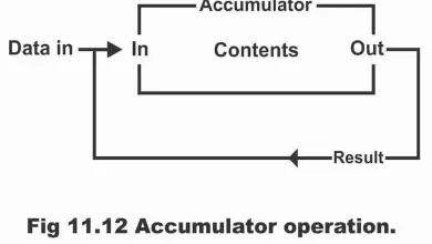
A digital device, which is used for the measurement of time period of any waveform, is called time period counter. In figure 12.12, logic diagram of instruments used for measurement of time period has been illustrated, by using basic concepts of which, a time period counter can be manufactured. Remember, this diagram has been prepared by making slight modifications in the block diagram of frequency counter as shown in figure 12.8 (i.e. by means of slight modification in a frequency counter, it can also be changed to instruments for measurement of the time period)
According to the diagram, unknown input or unknown voltages are first received on conditioning amplifier (an amplifier which converts an unknown input wave form to an accurate square type wave form, is called conditioning amplifier). A periodic wave form is produced from its output (of specific and equal intervals), which is compatible with TTL circuit. Then this compatible wave form is received on a JK flip – flop and output of this flip – flop is used as an ENABLE gate signal. As this output is high for time t, therefore it is exactly equal to the time period of the unknown input voltage. Oscillators and dividers, provide a series of pulses, which transmits through the count gate and operate as a clock for the counter. In such a situation, contents of counter and display unit become proportionate to the time period of the unknown input signal.
Figure 12.12 – instruments to measure time period

Suppose that counter and display unit illustrated by figure 12.12 has a capacity of 5 decimal digits and divider switch has been set in such a manner that it provides 100KHz square wave, which is used as clock pulses. In such a situation, if unknown input consists of 200Hz square wave, then what time period “t” an enable gate tends to reflect on display after time “t”. Its answer is as follows;
Suppose that counter and display are initially on 0000. A 200Hz input signal, generates following enable “t” gate;
t = 1 / 200 = 5000µs
Here, 100KHz square wave, which is used as a clock, is basically a series of positive pulses having a distance of 10s between them. Therefore, during the gate time t, counter advances by 5000/10 = 500 counts and the same thing is going to be reflected on display. As every clock pulse reflects 10µs, thus display represents following value for the time period of unknown input.
500 x 10 = 500µs
Remember that correction of counter and display tends to be 1.
In figure 12.13, an instrument consisting of 4 decimal digits has been illustrated, which is used for the measurement of any periodic wave form. It basically similar to the frequency instrument shown in figure 12.11 except that slight modification has been done in it. The first amendment which has been done in it is that its clock can be advanced to 1MHz range. The second modification is that its divider consists of a combination of a buffer amplifier and 3-decade counters. This provides 1ms spacing clock pulses on the counter with 1µs, 10µs and 100µs. amplifier performs conditioning of unknown input (i.e. amplifier converts unknown input to an accurate type wave form). This unknown input is transmitted on flip – flop after the amplifier, which produce enable gate signal. After this, just similar to strobe and reset operations in a frequency counter, such operations also take place on it.
Figure 12.13 – Four – decimal – digit period measurement instrument

Remember that a single instrument can also be manufactured quite easily for frequency and period measurement through the application of 1MHz clock, 7-decade counters, a divider and some simple mechanical switches.
Moving Message Display
The digital device which displays any message continuously in a moving form, is called moving message display. As this method for displaying any message or advertisement is exceptionally attractive, therefore it immediately becomes everybody ‘s center of attention. Therefore, this method is extraordinarily popular. Moving message display is commonly used in show cases present in the markets, clubs, parties, marriage halls, cinema halls, stadiums and some specific recreational spots besides occasionally using for security purposes.
The logic circuit block diagram of a moving message display has been illustrated by figure 12.14.
Suppose that we want to display ABCD in a moving message form. For this purpose, several LEDs are specifically set on a printed board circuit (PCB) according to the message. Then logic circuit (which is going to be discussed ahead) will first illumine alphabet A, then B, C and D. After this all LEDs will be deactivated or turn off. And will repeat this operation again in same sequence.
Figure 12.14

In figure 12.15, logic diagram of a moving message display has been illustrated, which consists of a 555 timer (which operates as a-stable multi-vibrator, and its output can be changed through changing the value of R2), 4-bit static shift registers 4015 having 16 pins and dual in line package, control circuit or clock (which is synchronized with all 4 registers) and display (which is normally indicated by a 7-segment display i.e. 7 LEDs). Through the application of two 4015 registers, 16 outputs can be received and each output can operate a single alphabet. Thus, a total of sixteen alphabets can be operated through the application of this circuit. However, if there is a need to display more than 16 alphabets, then more shift registers can be added with this circuit. The SW1 switch set on this circuit is a single pole double throw (SPDT) switch, the operation process through which is as follows;
When SW1 is connected to R6, in such a situation circuit starts to operate and all alphabets irradiate one by one until last alphabet also illumines. After this, high signal received through switch activates or turns on all the reset pins and as a result of which, all alphabets turn off. As a consequence, last output becomes low and reset pin turns off. As a result, the entire afore – mentioned process (i.e. process of illuminating all alphabets turn by turn) starts once again.
Figure 12.15

If SW1 switch is connected to R5 instead of R6, then supply VCC connects to the first register’s D input via resistor R3, as a result first alphabet irradiates. All alphabets will keep illuminating turn by turn with every clock pulse and when last alphabet has been illuminated, transistor’s base will become high as a result of this. Thus, transistor will saturate as a result of which input of the first register D will get low and first alphabet will turn off. As such, all alphabets will turn off one by one with the striking of every clock pulse. When final output is illuminated, it brings transistor into a cut – off mode. Therefore, input of the first shift register D becomes high and afore- mentioned restarts. Thus, all alphabets illuminate one by one in an advance moving sequence and then turn off in a sequence one by one, until the first alphabet illumines once again.
Remember that every alphabet is being formed as a result of combination of multiple LEDs. An alphabet requires a maximum of 100 LEDs; however, it also depends on the size of the alphabet. Moreover, output current of every alphabet tends to be pretty low. Suppose that an alphabet requires 100 LEDs and every LED requires 15mA current, then total current of every alphabet will be 1.5A. it means that we will have to install a power transistor of 1.5A to 2A in order to operate LEDs and transistors base should be connected to the registers’ outputs.
In figure 12.16, a driver circuit has been depicted having been prepared by means of connecting transistors with LEDs in a Darlington manner. As such, 100 LEDs can be operated or illuminated. As register’s output is received on this driver circuit, therefore the driver circuit transmits its output on displays according to the register’s output (as illustrated via figure 12.14). As a result, any designed moving message tend to start displaying.
Figure 12.16

Previous Topic: How to design digital clock using counters decoders and displays
Discover more from Electronic Clinic
Subscribe to get the latest posts sent to your email.