Microprocessor Architecture / Organization in Digital Electronics
Last Updated on April 18, 2023 by Engr. Shahzada Fahad
Microprocessor Architecture / Organization
The microprocessor is the brain of a computer. Which devices or components do exist in the brain or microprocessor of a computer, it can be elaborated by means of its architecture or organization. The following items or components are common in all types of microprocessors, however, slight differences exist in their size as well as characteristics.
Accumulator
An important and most frequently used section of a microprocessor is the accumulator. Accumulator is a storage place or a register, where in stored contents can be changed by means of different techniques. For example, we can increase an accumulator’s contents according to the contents of a memory location. Generally, a result obtained through an operation can also be stored in an accumulator or can be provided on an accumulator. As can be seen via accumulator operation reflected in figure 11.12.

Micro-processor fetches the accumulator’s contents and incoming data performs some sort of operation on them. And the result thus achieved by means of this operation is fed back on to accumulator. Sometimes, no data is received on a microprocessor, in such a situation only an operation on the accumulator’s contents is carried out. Some microprocessors consist of just one accumulator, however, in majority of microprocessors, more than one accumulator exists.
General Purpose Register
General purpose registers are simply similar to an accumulator. The only difference being that general purpose registers are only temporary type of storage providing locations, whereas accumulator is a specific type of register which carries out storage operation for some special purposes. General purpose registers are different from an accumulator in the sense that action takes place on it as a result of just a data contrary to an accumulator operation (whereas in accumulator action takes place on the basis of result obtained via operation in an accumulator and data entering into a microprocessor (as has been detailed above) and result of this operation is not fed back again on the register (as has been illustrated in figure 11.13 by operation of a general purpose register). Remember that micro-processors often change contents stored on general purpose registers.
A question may also arise into your mind that when a RAM exists on a micro-processor, which stores information on a temporary basis, then why does a processor need a general-purpose register. Its answer is speed. Because data in registers can access extremely speedily as compared to data in RAM (i.e. they can gain access up to a certain location at an amazing speed)
Program Counter / Instruction Pointer
A special purpose register objective of which is to provide track to the next instruction being fetched through memory, is called program counter.
We know that instructions are stored on memory and generally memory locations in thousands, lacs or crores of number do exist, therefore wherefrom a micro-processor receives next instruction. It is not the function of a microprocessor to take care of this track, rather this task is performed by counter. Program counter is a very special type of register, the function of which is only to take care of location of the next instruction being received on a microprocessor, which the microprocessor has to use. In figure 11.14, this function of the program counter has been illustrated. Program counter or instruction pointer actually elaborates the address of the next instruction being received on a microprocessor. This process of receiving instruction is generally known as “fetching of instruction” and the time which is required for this purpose, is called fetch cycle.
Figure 11.14 – Program counter operation

Index Register
Another type of register the basic objective of which is to point data being used in the tables, is called index register. Just like an index of a book helps a person to search some information, similarly an index register helps in searching certain data. index register is generally used as a collaborator for accessing data stored on the tables within a memory. It is possible to make an increase or decrease in index registers, however generally it cannot perform other arithmetic or logical characteristics.
Status Register
Status register which is also sometimes known as a condition code register or flag register, is a special type of register which provides track to arithmetic, logical and other operations’ specific facts related to conclusions or take care of the track of specific facts. In other words, a special register, in which the discrete bits existing, represent status of specific conditions, is called a status register. This register enables it for a microprocessor to test certain conditions (or this register enables the microprocessor to test certain conditions) and could perform alternative functions on the basis of these conditions. This task is generally accomplished through the application of flags.
Status register can be divided into two individual bits, each of which has its own distinct functions. Every bit of status register is called a flag. Every flag has a track, which has specific conditions. As a consequence of these conditions, every instruction or operation does not always affect every flag. Some instructions affect multiple flags and some of the instructions have no impact whatsoever on flags. In figure 11.15, model of a specific status register has been illustrated.
Remember that the following logic are used with respect to flags;
If any condition occurs on a register, flag applies 1, which means “Yes” or “True” or that this particular condition has taken place. If no condition happens, flag uses 0, which means “NO or “Untrue” or this state did not take place. When flag represents 1, it denotes setting of the flag and when it denotes 0, it represents its “clear” state.
Stack and Stack Pointer
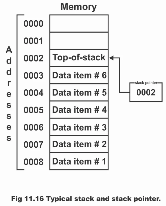
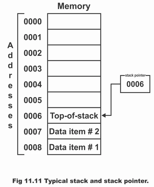
There is a specific place inside a stack memory (normally inside RAM) where in specific parts of important data or information can be stacked from top to bottom in a slight abnormal manner. The construction of this static is of FILO type i.e. “first – in – last – out” (i.e. information which enters first, removes or ceases right in the end). In figure 11.16, a specific stack and stack pointer has been demonstrated. In an ordinary memory (or main memory) any data can be accessed in any sequence; however, stack is designed in such a manner that first of all only the top stack is being accessed (i.e. just top data on a stack can be accessed first, then other top to bottom data is accessed turn by turn). For example, if you want to store any new data on a stack, this data will store on the top and even if you want to remove or receive some data from the stack, top data will be removed first.
Figure 11.15 – Model of a typical status register (b’s represent bits)
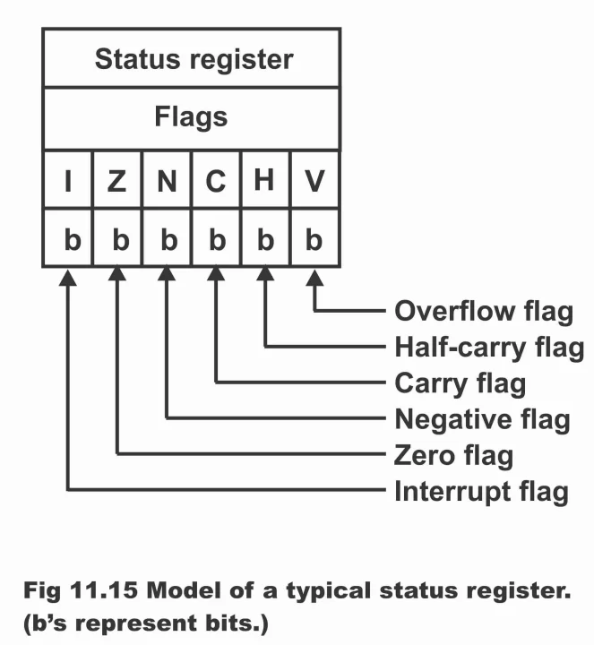
Figure 11.16 – Typical stack and stack pointer
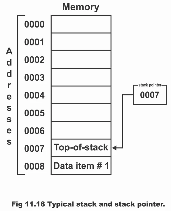
Now we see that how does the situation illustrated in figure 11.16 occur? In order to understand this process, look at figure 11.17. Suppose that data item number 1 is the first item which we want to bring or store on a stack. At this time, as stack pointer has been pointing towards memory location 0008, therefore data item number 1 stores in stack stores on memory location 0008. The process of storing data on static is called pushing of data within the stack. This process is similar to as data is being pushed from the top on a stack. In figure 11.8, data item number 1 has been illustrated being pushed inside the stack, whereas in such a situation, stack pointer has downgraded by one step i.e. 0007. Which means that now stack pointer has been pointing towards memory location 0007. As location 0007 is now the top most location on stack, therefore new data will now store on this pointed position. Now if data item #2 is pushed inside the stack, this data will move towards stack pointer’s pointed position 0007 as has been illustrated by figure 11.19. After this operation, stack pointer comes one step further down (i.e. 0006). If this process of data pushing continues in a similar fashion, a situation like the one illustrated in figure 11.16 can develop;
Figure 11.17 – Typical stack and stack pointer
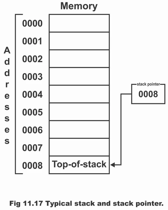
Figure 11.18 – Typical stack and stack pointer
If some data stored on a stack is required to be removed anytime, we can remove this data from the top of the stack. This operation is called data pulling or popping from stack. In order to remove some data present on a stack, the entire operation mentioned above has to be reversed. As we keep continuing removing data one by one, stack pointer drops step by step, which means that it will next high memory address.
Figure 11.19 – Typical stack and stack pointer
Previous Topic: Microprocessor Operation or Function in Digital Electronics
Next Topic: 8085 Microprocessor Architecture in Digital Electronics
Discover more from Electronic Clinic
Subscribe to get the latest posts sent to your email.


