How to design digital clock using counters decoders and displays
Last Updated on April 24, 2023 by Engr. Shahzada Fahad
Table of Contents
Introduction
How to design a digital clock using counters decoders and displays- There is no department of life in the present world where in an extensive application of digital electronics is not being made. From a wrist watch to a computer, digital electronics is enormously being utilized everywhere in all type of instruments or devices. Digital electronics has caused a revolution in the field of science and engineering. Application of computer, which is a greatest example of digital electronics, has increased so tremendously that it has virtually encompassed every spheres of life.
Digital technology is massively being used nearly for all types of tests and working instruments e.g. watt meter, volt meter, ampere meter, frequency meter, power meters, watches, clocks, moving display, frequency counters, radio, TV, receivers, measuring instruments, radar, warfare and aircrafts, guided missiles, coded communication (e.g. telegraphy, telephony, telex, tele printers etc.) X-rays, electro therapy, CT scan, ultra sound and all type of testing instruments, different types of counters, control instruments and automatic control systems, wireless communication (e.g. radio broadcasting, TV broadcasting, satellite communications, audio and video systems e.g. record player, tape recorders, stereo amplifiers and CD ROM etc. In this article we will discuss, just, a few applications of digital electronics e.g. digital clock, frequency counters and moving message display are being elaborated.
Digital Clock
A digital or logic device which displays time in digits, is called digital clock. As counters, decoders and displays are used in the design of a digital clock, therefore digital clock reveals a very interesting application of counters and decoders. Digital clocks are often commonly used in mosques, shopping centers, hospitals and educational institutions.
A 120V AC supply having 60Hz capacity, is used for displaying hours, minutes and seconds during the manufacturing of a digital clock. The basic purpose behind using a 60Hz power line frequency is that this frequency can easily be changed into seconds, minutes and hours by means of dividing this frequency via clock’s frequency divider section. In other words, in order to get one pulse/ second, a 60 cycle per second frequency is divided by only 60. As a result, a waveform of one cycle per second or Hz is received. Therefore, the usage of a 60Hz signal in a basic digital clock has tremendous importance as an excellent controlled signal. If this 1Hz waveform is further divided by 60, one pulse / minute waveform is obtained. Similarly, if this one pulse per minute waveform is further divided by 60, we get one pulse / hour waveform as a result of this operation. And this is the concept on the basis of which a digital clock is manufactured.
These different functions taking place in a digital clock have been illustrated through a block diagram in figure 12.1. According to the figure, the first counter being divided by 60 divides 60Hz power signal received on it by 60 and converts it into a 1Hz square wave or 1 cycle / second square waveform. Thus, a 1Hz square waveform is received. The second divide – by 60 – counter once again changes the incoming 1 cycle / second status of square waveform and converts it into 60 discrete states (i.e. the second counter being divided by 60, further divides the incoming pulse into 60 sections). This counter is known as the seconds counter (as has been illustrated in the figure) because 60 discrete states of this counter is decoded for providing such signals, which display seconds.
Figure 12.1 – Digital clock block diagram

Third divide-by-60 counter once again changes its state after every one minute and comprises 60 discrete states (in other words, third divide-by-60 counter further divides the incoming 1 cycle/ minute pulse or waveform into 60 sections). As this counter can be decoded to provide such essential signals, which expresses minutes (or as this counter is decoded in order to display minutes), therefore this counter is known as minutes counter.
The last counter shown in the figure changes its state once after every 60 minutes or after every one hour. That’s last counter divides one cycle / minute wave by 60 and changes it to one cycle / hour wave, which if divided further by 12, 12 hours can be displayed with the help of a decoder. This counter is known as hours counter.
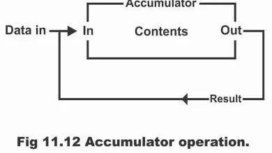
There are several methods to use this counter. It is attempted that a counter is designed in such a fashion that minimum hardware is required. The first counter just carries out the divide- by – 60 function and it does not require a decoder. As a result of unimportance of a decoder, this type of counter can easily be designed with minimum flip – flops.
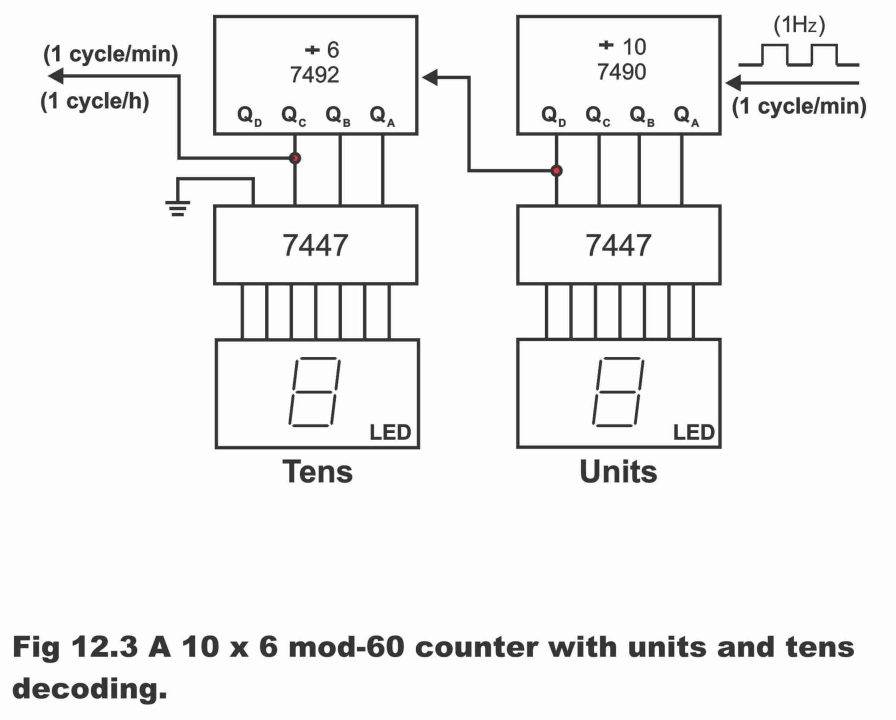
For example, the divided – by – counter can be used through cascading counters i.e. 10 x 6 = 60 or 12 x 5 = 60. (In other words, divided – by – 60 counter is linked together with a divided – by – 12 counter in such a manner that output of one combine on input of the other) For this purpose, TTL MSI 7490-decade counter can be used as a divided – by – 10 counter and TTL MSI 7492 counter can be used as a divided – by – 6 counter. As a result of recombining or cascading (process of applying one counter’s output on second counter’s input, is called cascading) of both, a divided -by- 60 counter is received. This has been illustrated via figure 12.2. Amplifier being provided on input, provides 60Hz square wave of an appropriate amplitude in order to drive 7490 (extreme limit or height of any variable quantity is called its amplitude). Here, 7492 has been connected as a divide – by – 12 counter (i.e. 7492 behaves or operates like a divide – by – 12 counter). However, only QA, QB and QC outputs are applied alongside it. In this manner, this counter basically operates as a divide – by – 6 counter.

The second counter having seconds on the system also happens to be a divided – by – 60 counter and it is designed and used in the same manner. However, seconds counter must necessarily have to decode. In order to decode this counter, generally a 10 – mod counter is mounted with a 6 – mod counter on a series. In this way, divide – by – 60 develops into such a counter which decodes 60 seconds in one minute. As a result of decoding of 10 – mod, second’s unit digits and decoding of mod – 6 counter, seconds tens digits appear.
As both 7490 and 7492 counters count directly in 8421 binaries, therefore by means of applying a 7447 decoder/ driver with each, two 7 segment indicators can be operated or driven. This has been illustrated via figure 12.3. It must be inculcated here that a 7492 counter has been set as a divide – by – 12 counter. However, only QA, QB and QC outputs are used in order to decode or drive 7447. As a result, 7492 counter drives 7447 decoder – driver as a divide – by – 6 counter.
Figure 12. 3 -A 10 x 6 mod – 60 counter with units and tens decoding.
Just like seconds counter, the minutes counter also functions exactly in similar manner, except that a 1 cycle / minute square wave is received on it (i.e. minutes counter) from the seconds counter. And a 1 cycle per minute output tends to become available from it (i.e. minutes counter). divided – by – 12 hours counter must also necessarily be divided by 12 so that it can display hours into different states. For this purpose, a mod – 10(i.e. 57/ 74160) decade counter is connected to a single flip – flop E on a series. This has been illustrated in figure 12.4. As such, it becomes a divided – by – 20 counter (i.e. 10 x 2 = 20). However, a feedback is being used in order to make it a 12 – mod counter.
The hours counter starts count from 00, 01, 02 to 11 and then starts back its count again from 00 state. As soon as counter starts count from 11 to 12, NAND gate set on figure 12.4 remains low and as result, 74160 clears and becomes 0000 immediately and E flip – flop also resets accordingly and becomes 0. In fact, counter jumps and skips 8 counting numbers existing between these two, while counting from 11 to 00. Thus, this counter is a mod – 12 hours counter and 74160 presents in it, provides units of hours, whereas flip – flop provides tens of hours.
Figure 12.4 – Mod – 12 hours counter

In case, power supply power supply turns off and then on, state of flip – flops present in the digital clock become useless and in order to make it useful, the clock is required to be reset once again. In order to set clock easily, push buttons are set on to the circuit of digital clock as has been illustrated vide figure 12.5. As we press SET HOURS push button, hours counter proceeds its count at a rate of one – count – per second. As such, by means of pressing hours push button, hours counter can be set on the required hour. Similarly, minute push button on minutes counter can also be set on required minutes by means of pressing set minutes. As a result of pressing seconds push button, signal is removed from seconds counter and as such, clock time is harmonized or synchronized with the standard time.
Figure 12.5 – Digital clock

In other words, as time on a digital clock changes and becomes different from the standard time when a power supply turns off and then on, therefore it is necessary to set clock according to the standard time once again, when a power supply turns off and then on. For this purpose, separate push buttons are mounted along hours, minutes and seconds counters inside the clock, by means of pressing which, clock’s hours, minutes and seconds count can be changed in order to harmonize it with the standard time.
Remember that through large scale integration (LSI), it is possible to manufacture a complete digital clock on a semi-conductor chip. Such type of units is commercially available and they conduct operations in accordance with block diagram of the digital clock illustrated in figure 12.5.
It must be inculcated into mind that in order to manufacture a digital clock, such type of chips (e.g. 5387, 5318 etc.) are commonly available on commercial basis, which have multiple advantages (e.g. 50 or 60Hz operation, 12 or 24 hours display format, 59-minute sleep time and 24-hour alarm setting etc.) and through the application of which, digital clock’s according to one’s own needs and sweet-will can be designed.
Alternative Explanation
For further explanation, a simple block diagram of a digital clock has been illustrated in figure 12.6 (a) and its detailed block diagram in figure (b). According to figure (a), first a 60Hz frequency is provided on clock’s input, which is received by the clock’s divider section and converts it into seconds, minutes and hours. After this, these pulses having been divided into one pulse / second, one pulse/ minute and one pulse/hour, are counted in the counter and then these pulses store into count accumulator section. Then decoding operation starts on these pulses stored on count accumulator section by means of a decoder. As a result, correct time displays on the display set on clock circuit’ output. it is obvious from the figure that entire operation of a digital clock occurs in frequency divider, counters and decoder sections, which can easily be read by means of display. Thus, a very interesting application of counter, decoder and display can be seen in a digital clock. In this diagram, a Time- set has also been shown along control section, the task of which is to set time when required (i.e. when power supply turns off and on).
According to the detailed diagram of a digital clock illustrated by figure (b), when 60Hz input signal is received on clock’s input, first frequency divider divides this 60Hz input signal by 60. Thus, 1 pulse / second output is received from the first frequency divider’s output. This one pulse / second output is transmitted on up – counter, which counts from 00 to 59 and then re- sets again on 00. This second’s counter provides its output to decoder, which decodes (converting digital information to decimal numbers is called decoding) this output and displays it on two 7 segment LED displays set on top towards the right of the figure (b).
When frequency divider circuit shown in the middle of figure (b) receives first divide – by – 60 circuit’s pulse on one pulse per second output, it divides it by 60 and converts it into 1 pulse / minute output. This one pulse per minute output transfers to 0 to 59 minutes counter, which is located in the middle of the circuit. This up counter counts from 00 to 59 and then resets. Then output of minutes count accumulator transfers on to decoder, which decodes it and displays it on two 7 segment LEDs set in the middle of figure (b).
Figure 12.6 – (a). Simplified block diagram of a digital clock (b). More detailed block diagram of a digital clock
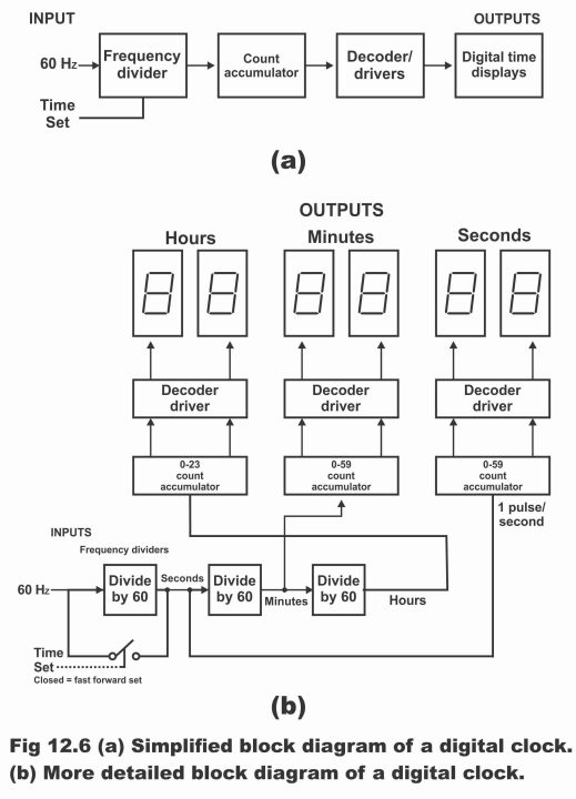
Now look at the operation of divide – by – 60 circuit (with an input of one pulse / minute) which is located on the bottom part towards right most side of the figure (b). When this frequency divider receives one pulse per minute input, it divides it by 60 and converts it to 1 pulse per hour output. This one pulse per hour output transfers to hours counters located on top most part, towards the left side of figure (b). This hour count accumulator counts from 0 to 23 hours, its output decodes side by side and displayed via two 7 segment displays fitted towards left side of the figure. Thus, this digital clock operates similar to a 24 hours clock, which can easily be converted to a 12 hours clock also by means of converting its 0 to 23 counters to 1 to 12 counters.
A time set control also exists in digital clock’s figure (b) in order to set time. when switch is closed (remember that a logic gate is used instead of a switch) displays counts ahead very quickly. Thus, time can be changed very quickly at one’ will. This switch bypasses the first divide by 60 frequency divider, so that clock could progress ahead 60 times quickly as compared to its normal rate, while setting time. if the second frequency divider circuit is also by-passed just like the first one, then time set control can be converted to a speedy fast forward set control. This technique is commonly used in digital clocks.
In order to understand what does exist inside a divide by 60 frequency divider, look at figure 12.7 (a), which represents block diagram of a divide by 60 frequency divider, according to which a divide by 60 counter consists of module – 6 and a decade counter (i.e. divide by 6 and divide by 10 counters). According to the figure, divide by 6 counter has been providing its output to the divide by 10 counter. As such complete unit (which consists of two counters), divides the incoming frequency by 60. In this example, 60Hz input, converts to 1Hz on reaching output.
A detailed wiring diagram of a divide by 60 counter circuit has been illustrated in figure 12.7 (b). According to this figure, a divide by 6 counter is being assembled through a combination of three JK flip – flops and a NAND gate, whereas 74192-decade counter has working as a divide by 10 unit. When this circuit is applied 60Hz input from the left side, it converts it to 1Hz output, which connects with QD output of counter 74192.
Figure 12.7 – Divide – by – 60 counter (b). wiring diagram using TTL IC

Remember that practically, output of digital clocks commonly available, is normally represented by just hours and minutes and frequency divider, counters and decoders all exist on a single LSI chip. However, such types of chips are also commonly available in markets which have some extra features e.g. 12- or 24-hours outputs, calendar, alarm controls and radio controls etc.
Frequency Counter
A frequency counter is a type of digital instrument, which is used for the frequency measurement of any periodic wave form. Frequency counter indicates frequency of any circuit in decimal numbers and it can measure from frequency as low as few cycles per second (hertz) to frequency as high as thousands of megahertz (MHZ). Just like digital clocks, decade counters are also used in frequency counter.
In figure 12. 8, basic diagram of a frequency divider has been illustrated according to which, a frequency counter comprises following segments;

Clock Oscillator or Clock Generator
Its function is to provide frequencies of different range. Clock oscillator is actually a 555 timer in the shape of an IC, which operates in a- stable mode. Any time period can be determined by means of selection of R1, R2 and C components in a correct form (remember that time period and frequency are inversely proportionate to each other i.e. F = 1/T). In order to get three different types of time periods from clock oscillator, C1, C2 and C3 capacitors are used. This has been indicated by figure 12.9. In such a situation, formula of time period is as follows;
T = 0.693 (R1 + 2R2) x C
It is obvious from the aforementioned formula that if we keep values of R1 and R2 constant, then different time periods can be obtained only by means of changing the value of C1. By means of setting the values of C1, C2 and C3 as 1nf, 1µf, 1000µf (whereas C’s value being 0.01µf, R1 value 510Ω and R2 value 470Ω) we can get time period for a second, one milli second and one micro second. In such a situation, different frequencies are obtained from every capacitor’s output (i.e. 1Hz from C1, 1KHz from C2 and 1MHz from C3).
Figure 12.9

Divider
As the name suggests, its function is to divide input frequency coming from the clock oscillator.
AND Gate
AND gate performs the function of ANDing. A frequency signal from the dividers’ output, is found on this gate’s input, whereas its other input consists of an unknown frequency signal.
Counter
The function of a counter is to count unknown frequency. Its input is output for an AND gate.
Previous Topic: 8085 Microprocessor Architecture in Digital Electronics
Next Topic: Making Counter and Moving Message Display in Digital Electronics
Discover more from Electronic Clinic
Subscribe to get the latest posts sent to your email.