Megger Tester for Insulation Resistance test, Construction and working
Last Updated on September 12, 2021 by Engr. Shahzada Fahad
Table of Contents
Megger:
Megger is used for the measurement of insulation resistance. It also measures the resistance of the insulator. The megger measures insulation or high resistance in terms of mega ohms. There are different types of megger instruments depending upon on the voltage rating such as:
- 500V
- 1000V
- 5 KV
Insulation and insulation resistance:
Insulation in simple terms means that it is offering some resistance to the current or heat flow. The insulation resistance of all appliances should be checked at regular interval of time because it gives the information about the condition of the appliance or wire. The insulation resistance depends upon the moisture, temperature, test voltage and duration of the appliance. The internal resistance of the wire is very less due to which the current easily flow in it. On wire we have small or thin coat of rubber like a synthetic material which is called insulation and without this insulation what will happened? If the wire has no insulation and it touches the equipment body or if a human touch this wire there will be flow of electric current and causing electric shock. So for this reason the wires covered with insulation. So this in mind insulation is a material which offers very high resistance to the flow of electricity. Insulation offers resistance to the leakage current.
Why we perform megger test?
When the magnitude of the leakage current exceeds the design limit which the cable can’t withstand, the cable will no longer deliver energy efficiently. All the electrical systems used in various areas like homes; industries, hospitals, automobiles etc are interconnected using electrical wires. So in order to protect the electrical system from the external or internal damage we must check the insulation of the electrical wires.
The insulation resistance check the insulation quality of the electrical system and to avoid any major or minor electrical shocks to operator. In over time it may happen due to damage or moisture or contamination when we have leaking of current from the conductor. It can cause various issues like light tripping because moisture going into the walls that will allows the electricity to jump out of the conductor and trip a switch, We can also see this issue in portable appliance like electric kettle which has metal casing so if we have issue in insulation. So by touching the appliance we will feel shock.
Let us suppose that we are manufacturing transformer so the insulation that we will use for the winding will be tested before use; to check whether that resistance is suitable for the winding or not. If we use the insulation without testing then there is possibility that if the resistance is not correct it may damage the transformer. Also it can cause shocking due to the failure of the insulation. So to avoid from these types of faults we do megger testing.
Megger Construction:
The parts of the megger are shown below, the armature of the generator is rotated by the hand driven crank lever. The clutch mechanism is designed to slip at predetermined speed. This facilitates the generator to maintain the constant speed and hence the constant voltage to while testing the two coils A and B constitute a moving voltmeter and an ammeter both are combine to form one instrument. The hot terminal of the equipment whose insulation resistance is to be measured is connected to the testing terminal X. The terminal Y is connected to the body of the instrument which is generally grounded. When the crank handle will be rotated the voltage will be generated in the generator. The megger can generate up to 1000V with the help of generator present in it. The generator voltage is applied across the coil A through resistance R1. When the terminal X and Y are free initially no current flow through the coil B. The torque produce by the coil A rotates the moving element to show infinity.
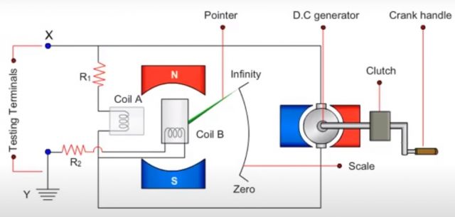
Deflecting coil or current coil connected in series and allows the flow of electric current taken by the circuit is being tested. The control coil is also known as pressure coil is connected with across the circuit. Current limiting resistor connected with the control coil and deflecting coil to protect damage in case of very low resistance in external circuit.
As the voltage increases the in external circuit the deflection of the pointer increases of current. This shows that when current increases the resistance will decreases and vice versa.
Working Principal of the meggar:
The principal of megger is based on the moving coil in the instrument. When current is flowing in a conductor which is placed in magnetic field it will experience a torque.
A torque is developed due to the interaction of the current flowing through the pressure coil and current coil. Flux is produced by the permanent magnet. The deflection of these coils is proportional to the resistance to be measured.
Torque developed due to current in the pressure coil.
I1=torque developed to current in coil 1
I2=torque developed to current in coil 2
Both the torques will be equal.
T1= T2
Due to the interaction current flowing through the pressure coil and current coil. The torque will be develop due to the current flowing in the pressure coil and current coil.
Φ I1 cosɵ = Φ I2 sinɵ
tanɵ = I1/I2
I1 = V/R
I2 = V/R^+RT
tanɵ = I1/I2
tanɵ = (V/R )/(V/R^, +RT )
Since R and R’ are constant therefore
ɵ ⍺ RT
Where ɵ represent the deflection and is directly proportional to the unknown resistance.
How to use megger?
The megger send test voltage to see whether there is leakage current in the wire or not passing through the insulation.
While testing the terminal X and Y are connected across the terminals and body of machine for the measurement. Now the current passes through the deflecting coil B. The deflecting torque produce by the coil interacts with the torque of the coil A rotates the element to indicate the resistance value. Voltage generated by this instrument is around 500 Volts. This generated voltage or current will move in wire or insulator whose resistance we want to measures. The combination of this voltage and current will produce resistance which will be show on the megger.
The megger consists of two terminals in which one is live and other is neutral. When there is no wire connected at the terminals of the megger and there is only air between the terminals. So when we move the lever the megger needle will move towards infinity which shows us that the resistance between the terminals are very high. When we short the two terminals then when we move the lever of the megger the needle will move towards zero which shows us that resistance is zero. So if we check instrument and the megger show zero resistance then it will show us that the instrument is short circuited.
Checking the voltage of the megger:
Now if we want to check the voltage of the megger we will connect the terminals of the multimeter with the megger and set the voltage of the multimeter on DC. When we will rotate the lever of the megger a dc voltage will be generated and will display on the multimeter. The voltage generation of the megger will depend on the movement of the lever when we move the lever rapidly maximum dc voltage will be generated.
Now a question may be arising in our mind that during generation of the voltage if we touch our hand with the wire of the generator what will happened?
The dc generator which is used in the megger having thin wire in the winding due to which the current generated will be less. So due to which we will not feel any shock.
We see in our daily life that when current flowing in wire and we touch the insulation of the wire we do not feel any current shock. The insulation has resistance which prevent the current to flow outward. When this insulation become weak then the will leak and there is chance of shock and the wire may catch fire. This insulation resistance is measured with the help of megger. This is special type of ohm meter which give resistance generally in mega ohm. The range of this meter is between 0.2 to 1000 MΩ. As we are measuring the resistance of the insulator therefore we take the resistance in mega ohm. As it measures the resistance in mega ohm due to which it is called megger.
Insulation test of transformer with megger:
Before performing the insulation test of transformer it is very important to check the wiring of the transformer. For example the connection of the transformer whether it is star connected or delta connected. Let us consider that the transformer on which we are performing the test are Y-Y connected. So in this particular case all the three primary terminal plus the neutral terminal will act as short circuit. The same condition is also applied to the secondary in which all the three terminal plus neutral will act as short circuit.

In order to check the insulation level or condition of the primary bushing or the primary winding. We connect the red probe of the megger with any primary terminal of the transformer and then we connect the ground terminal of the megger with the ground of the transformer. By performing this procedure we will get insulation resistance of the transformer. Similar process is perform on the secondary winding of the transformer.
Uses of Meggers:
Megger is used to measures the insulation resistance of the:
- Insulators
- Electric wires and cables
- Open and short circuit of winding
- Open and short circuit test of electric wiring
Types of Megger:
There are two types of megger:
- Electronic megger
- Manual megger
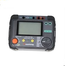
Electronic megger:
This type of megger is operated with the battery and gives output in digital form. The accuracy of the electronic megger is high because it uses digital display due to which we can easily read the insulation resistance. It can show us point to point insulation resistance. The dc voltage is already present in the electronic megger. It consists of different parts:
- Digital display
- Selection switches
- Indicator
- Wire leads
Electronic megger is safe and robust to use. It is very handy and we can carry easily from one place to another place. Its operation time is very less during testing.
Apart from the so many advantages it also has some disadvantages which are:
- It requires battery or external source of energy to energize
- The initial cost of the digital megger is high
Manual megger:
This type of the megger is manually operated with the help of the hand and gives output in analogue form. Its rpm is usually 160 which are produce by rotating the crank handle. In manual megger we create dc voltage by rotating the handle. It consists of:
- Wire leads
- Hand crank
- Analogue display
The manual megger operates without any external source. In emergency choice it can be excellent choice. It is cheaper than electrical megger.

Disadvantages:
- It is not very accurate
- As the manual megger consist of analogue display due to which it may be difficult to read the exact value of the insulation
- It is very time consuming because it is operated manually with hand
- Require very high care and safety during use
When we check wire or cable and the megger show zero resistance then it show that the wire is damage and when it show infinity resistance then we will get that this wire or insulator is correct.
Application of megger:
- The electrical resistance of the insulator can also be measured
- Electrical systems and components can be tested
- Winding installation
- Testing of relay , battery, ground connection
Advantages:
- It works like permanent dc generator
- Easy to operate for one person
- The resistance between the ranges zero to infinity can be measured
- It has very high measurement accuracy
Disadvantages:
- There will be error in reading value when the external resource has low battery
- Error due to sensitivity
- Error due to change in temperature
Use of megger:
- Transformer testing
- Circuit breaker testing
- Low and high resistance testing
- Motor winding testing
- Alternator winding testing
Discover more from Electronic Clinic
Subscribe to get the latest posts sent to your email.