Mobile Phone Detector with UTSOURCE service
Last Updated on February 25, 2024 by Engr. Shahzada Fahad
Table of Contents
Description:
The most powerful portable electronic gadget a person can control today is a cell phone or mobile phone. The demand for Mobile phones shown tremendous rapid growth in recent years drastically. The Mobile phone can transmit and receives the signal in the range of 0.9-3 GHz.
Principle of Mobile phone detector:
The basic principle of cell phone or mobile detector is to detect the RF signal frequencies. These circuits are designed in such a way that it rectifies low signal frequencies with very low noise of rate. When an inductor is placed near a RF signal frequency source it receives the signal through the principle of mutual induction. And the low power signals are amplified and transmit the power to any indicator which shows the response as we have used LED in our experiment.
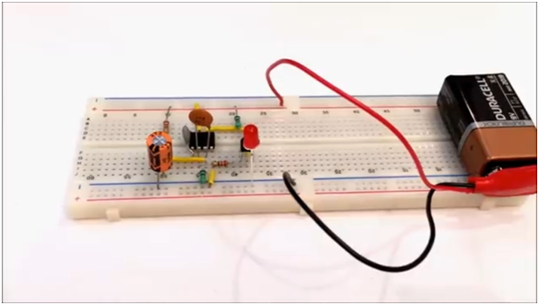
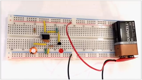
This can be really a fun project, using this small electronics circuit we can detect if someone is sending or receiving a message, or call is coming or someone is trying to call someone. As you can see in the picture above just a few electronic components are required for this project. Nothing expensive is used in this project. This project is ideal for school students and anyone can build this amazing small project in the lab.
After the basic working principle is understood, then the led can be replaced with a transistor to control a relay which can then control a buzzer. So, when anyone sends a message or receives a message the buzzer will turn ON.
Components Required for the mobile/cell phone detector:
- CA3130 Integrated Circuit (IC) https://www.utsource.net/itm/p/106486.html
- 1k ohm resistor (1) https://www.utsource.net/itm/p/6490099.html
- 100k ohm resistor (1) https://www.utsource.net/itm/p/6490099.html
- 2M ohm resistor (2) https://www.utsource.net/itm/p/6490099.html
- 47pF Capacitor (1) https://www.utsource.net/itm/p/6490092.html
- 22 microF Capacitor (1) https://www.utsource.net/itm/p/6490092.html
- 100microF Capacitor (1)https://www.utsource.net/itm/p/6490092.html
- BC548 Transistor (1)https://www.utsource.net/category/elec-component/transistors
- 9v Battery Clip https://www.utsource.net/category/accessories-tools/battery-case
- Connecting wires (as required)
- Bread Board https://www.utsource.net/category/accessories-tools/breadboard
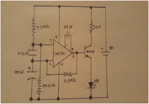
Circuit Diagram of the mobile phone detector:
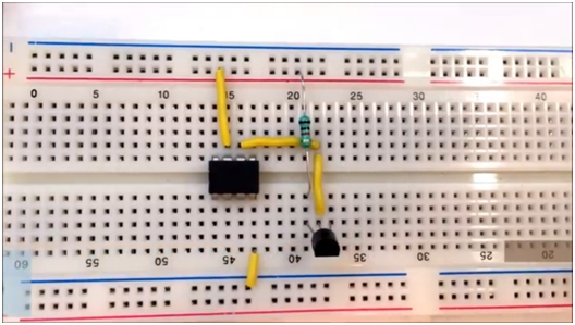
Step by step procedure:
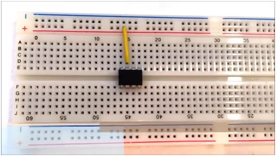
- Insert CA3130 on the breadboard
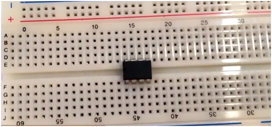
Before, I am going to explain the rest of the connections; first I would like to explain the IC CA3130.
About the CA3130:
CA3130 and CA3130A are op-amps “Operational amplifiers” that combine the advantage of both CMOS and bipolar transistors.
Gate-protected P-Channel MOSFET (PMOS) transistors are used in the input circuit to provide very-high-input impedance, very-low-input current, and exceptional speed performance. The use of PMOS transistors in the input stage results in common-mode input-voltage capability down to 0.5V below the negative-supply terminal, an important attribute in single- supply applications.
The CA3130 Series circuits operate at supply voltages ranging from 5V to 16V, (2.5V to 8V). They can be phase compensated with a single external capacitor and have terminals for adjustment of offset voltage for applications requiring offset-null capability. Terminal provisions are also made to permit strobing of the output stage.
CA3130 Pinout:
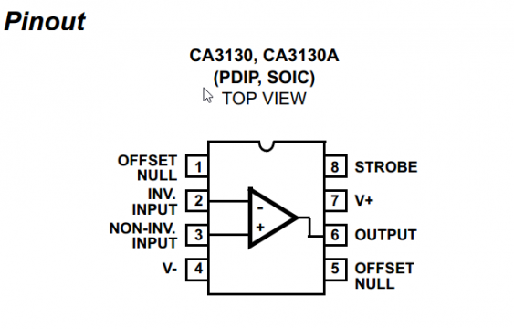
Download CA3130 datasheet
Absolute Maximum Ratings
DC Supply Voltage (Between V+ And V- Terminals) . . . . . . . . . .16V
Differential Input Voltage . . . . . . . . . . . . . . . . . . . . . . . . . . . . . . . .8V
DC Input Voltage . . . . . . . . . . . . . . . . . . . . . . (V+ +8V) to (V- -0.5V)
Input-Terminal Current. . . . . . . . . . . . . . . . . . . . . . . . . . . . . . . . 1mA
Output Short-Circuit Duration (Note 1). . . . . . . . . . . . . . . . Indefinite
Operating Conditions
Temperature Range. . . . . . . . . . . . . . . . . . . . . . . . . -50C to 125C
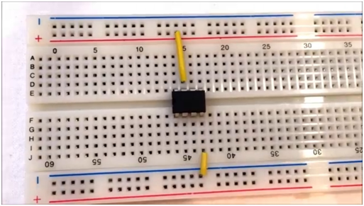
- Connect pin 7 to the positive rail
- Connect pin 4 to the negative rail of the bread board
- Now we insert the BC548 transistor on the Breadboard
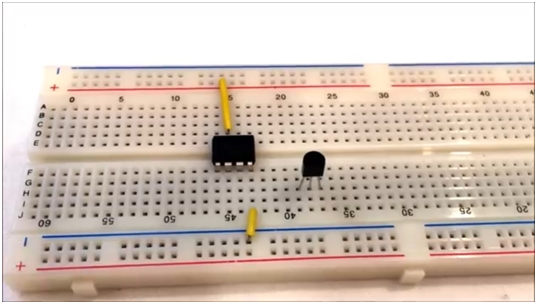
- Now connect pin 6 to the base of BC548
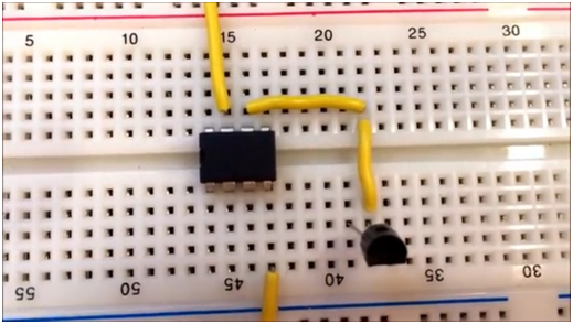
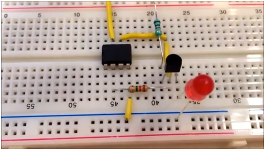
- Connect the collector of Bc548 to the positive rail using a 1K ohm resistor.
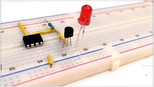
- Now insert the LED light on the BreadBoard circuit with the Anode connected to the emitter of BC548 and cathode connected to the negative rail.
- Connect pin 2 to the base of BC548 using a 2.2M ohm resistor
- Connect pin 3 to the negative rail using a 100k ohm resistor.
- Insert the 100micro F capacitor with one of its pin connected to the anode of the capacitor to the pin 3 and its cathode to the negative rail.

- Connect pin 3 to the positive rail using a 2.2M ohm resistor.
- Now connect pin 2 of the breadboard and another pin 3 with the 0.22micro Farad capacitor.

- Now Connect pin 1 of IC to the pin 8 using the 47pF capacitor.

- Connect the power supply to the breadboard of the circuit.
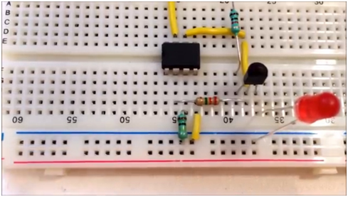
Testing of the circuit with the mobile connecting operation:
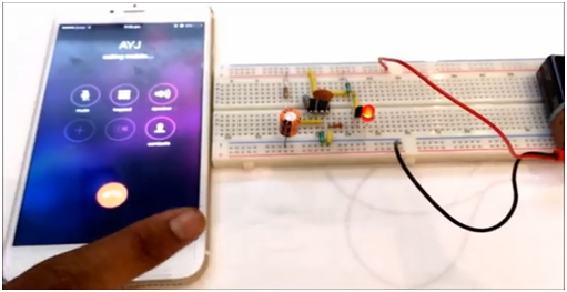
When we make a call from our phone (outgoing call) the LED of the circuit starts blinking till the phone rings.
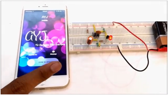
And when a phone call comes to our phone ( Incoming call) the LED also blinks. As you can see
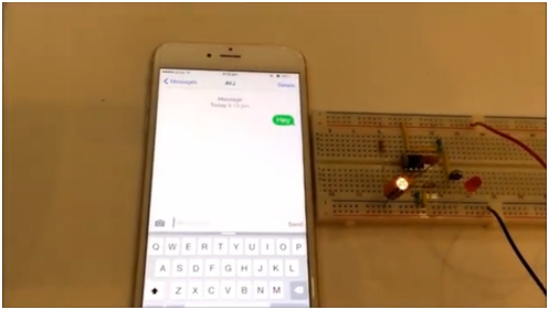
And we reject the call it stops blinking. It also works when a person sends a message to someone as you can see an outgoing text message.
Till the message goes it blinks and stops when it sends to the receiver. And same applies when it receives the message it starts blinking (Incoming text message).
So this circuit works flawlessly when the user sends or receives messages or calls to anyone.
Utsource.net Reviews
It is a trustworthy website for ordering electronic components to complete projects, free shipping can be provided on selected order for a 2-5 days delivery.

Conclusion:
The mobile phone detector works when the phone receives and outgoing calls and messages. This circuit works completely well to detect the signals of the phone simulations and all.
Discover more from Electronic Clinic
Subscribe to get the latest posts sent to your email.


What is the range through which it can detect the mobile phone and how we can improve it
This is a great project! I’m going to try it out soon.
only light is glowing. not blinking the the LED. Kindly tell me why this happen?
This project sounds intriguing! I love the idea of creating a DIY mobile phone detector using the CA3130. The detailed steps you provided really help demystify the process. I can’t wait to try this out and see how it performs. Thanks for sharing!
When I assemble this circuit (Mobile Phone Detector with UTSOURCE service), all connections are connected properly, and all the components are already done. The LED still glows. Please, tell me why this happened.