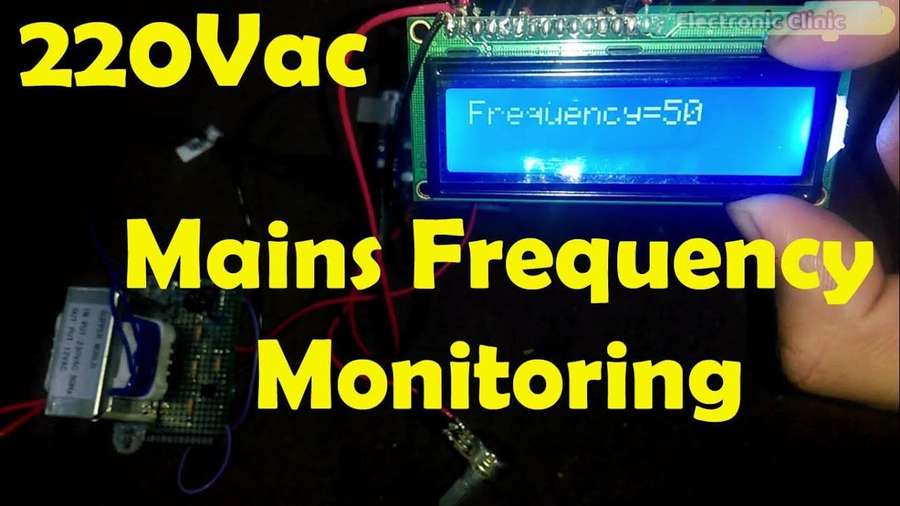
Nodemcu ESP8266 IOT Power Lines Mains frequency monitoring 50Hz
Last Updated on February 25, 2024 by Engr. Shahzada Fahad
Table of Contents
Mains Frequency Monitoring Project Description:
This Tutorial is based on the IOT Mains Frequency Monitoring system, in this Tutorial, you will learn how to make 110/220vac mains frequency monitoring system using Arduino, a Zero Crossing detector based on the EL817 Optocoupler, Nodemcu esp8266 wifi module, and Blynk application.
This is the 3rd version of the Mains Frequency monitoring system. While in the first version of the mains frequency monitoring system I used 2n2222 NPN transistor to send the on/off pulses to the Arduino Uno board and displayed the mains frequency on a 16×2 LCD.
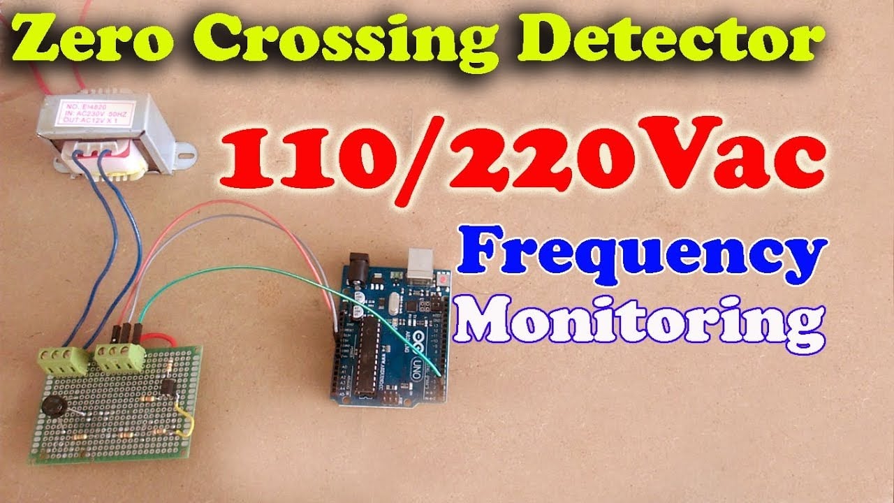
While in version2 of the mains frequency monitoring system I updated the circuit and replaced the 2n2222 NPN transistor with the EL871 Optocoupler to isolate the controller side from the ac voltage side. This way if anything happens on the transformer side will have no effect on the controller side.
This Tutorial is entirely based on version1 and version2, the zero-crossing detector circuit connections will remain the same. So I highly recommend you should watch my previous two tutorials on the mains frequency monitoring system, in which I explained everything in very detail. In this tutorial, I will only talk discuss the modifications. So in this tutorial, we will cover
- Modified circuit diagram explanation
- Interfacing
- Blynk application
- Arduino programming
- Nodemcu esp8266 wifi module programming
- testing
Amazon Purchase Links:
Other Tools and Components:
Super Starter kit for Beginners
PCB small portable drill machines
DISCLAIMER:
Please Note: these are affiliate links. I may make a commission if you buy the components through these links. I would appreciate your support in this way!
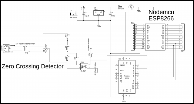
IoT Mains Frequency Monitoring System Circuit Diagram:
This schematic is designed in cadsoft eagle 9.1.0 version. If you want to learn how to make a schematic and PCB then watch my tutorial given below.
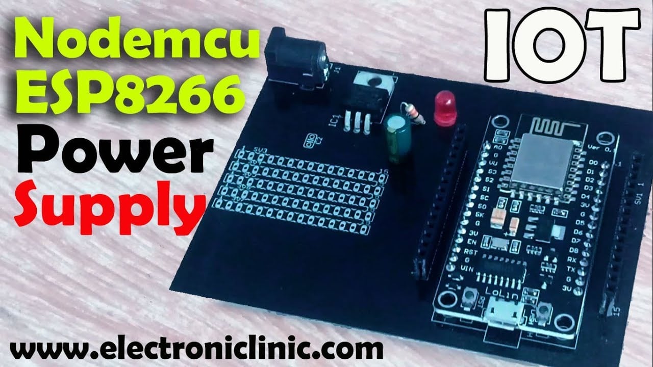
The zero crossing detector circuit is already explained in version2. This time I added a 5v regulated power supply based on the lm7805 voltage regulator. This is a dc female power jack where you can connect a 12v adaptor or battery or a Solar Panel. Two 470uf capacitors are connected at the input and output sides of the voltage regulator. A 330 ohm resistor is connected in series with the led; this is a current limiting resistor. a wire from the output of the voltage regulator is connected with the Vin pin of the Nodemcu module and the ground of the Power Supply is connected with the Arduino’s Ground. The Arduino and Nodemcu side has no physical connection with the zero crossing detector side. This power supply will be used to power the Nodemcu module. The Nodemcu TX and RX pins are connected the Arduino’s pin number 7 and 8.
Interfacing:

The zero crossing detector circuit connections are already explained in my previous tutorial, the only modification is the addition of the Nodemcu esp8266 wifi module and a 5v regulated power supply based on the lm7805 voltage regulator as explained in the circuit diagram. The Nodemcu module TX and RX pins are connected with the Arduino’s pin number 7 and 8. Make sure you connect the ground of the Nodemcu module with the Arduino’s ground. The 5v orange wire from the power supply is connected with the Nodemcu Vin pin and the grey wire which is the ground wire is connected with the Nodemcu ground pin. So this is the only modification on the hardware side. Now let’s setup the blynk application.
Blynk Application designing for IOT Mains Frequency Monitoring:
- First of all open the blynk application.
- Click on the new project and set the project name as mains frequency.
- Click on the choose device and select Nodemcu, make sure you set the connection type to wifi and then click on the create button, an authentication token will be send on your email id, which will be then used in programming, simply copy and paste it in programming. This is already explained in the video Tutorial given at the end of this Article.
- Click anywhere on the screen and search for the lcd widget and add it.
- click on the LCD widget, change the input type to advanced then click on the pin and select virtual pin V2. you can also change the screen color and fonts color if you want you can select any other color.

- Our Application is ready and now let’s discuss the programming….
Programming of the IOT Mains Frequency Monitoring System:
This project is based on two programs. One program is written for the Arduino while the other program is written for the Nodemcu esp8266 wifi module. First let’s start with the Arduino programming.
Mains Frequency Monitoring Arduino Programming:
This program is the modified version of the same program used in version1 and version 2 of the frequency monitoring system, this time I added the softwareSerial.h header file for creating a serial port on pin number 7 and pin number 8. So the Nodemcu module will be connected with the Arduino’s pin number 7 and pin number 8. Pin number 7 is the RX while pin number 8 is the TX. Then I defined a variable myString of the type String. This variable will be used to store the complete message consisting of the frequency value and the delimiter. The rest of the programming is exactly the same, finally added the frequency value and comma with the myString to make a complete message and then this message is send to the Nodemcu module. And make sure you empty the mystring variable for the new data.
|
1 2 3 4 5 6 7 8 9 10 11 12 13 14 15 16 17 18 19 20 21 22 23 24 25 26 27 28 29 30 31 32 33 34 35 36 37 38 39 40 41 42 43 44 45 46 47 48 49 50 51 52 53 54 55 |
#include <SoftwareSerial.h> SoftwareSerial nodemcu(7,8); volatile byte freqcount; unsigned int frequency; unsigned long timeold; int frequency1; int flag1 = 0; String myString = ""; void freq_fun() { //ac cycle, this interrupt function is run twice, so take that into consideration for //calculating frequency //Update count freqcount++; } void setup() { Serial.begin(9600); nodemcu.begin(9600); //Interrupt 0 is digital pin 2, so that is where the output from the transistor is connected //Triggers on FALLING (change from HIGH to LOW) attachInterrupt(0, freq_fun, FALLING); freqcount = 0; frequency = 0; timeold = 0; } void loop() { //Update frequency every second //delayMicroseconds(2000); delay(1000); //Don't process interrupts during calculations detachInterrupt(0); frequency = 60*50/(millis() - timeold)*freqcount; // 50 represents the frequency timeold = millis(); freqcount = 0; // Serial.print("Frequency: "); frequency1 = frequency/2; myString = myString + frequency1 +","; Serial.println(myString); nodemcu.println(myString); myString = ""; //Restart the interrupt processing attachInterrupt(0, freq_fun, FALLING); } |
Mains frequency Monitoring Nodemcu Programming:
For the complete explanation watch Video Tutorial given at the end of this Article.
|
1 2 3 4 5 6 7 8 9 10 11 12 13 14 15 16 17 18 19 20 21 22 23 24 25 26 27 28 29 30 31 32 33 34 35 36 37 38 39 40 41 42 43 44 45 46 47 48 49 50 51 52 53 54 55 56 57 58 59 60 61 62 63 64 65 66 67 68 69 70 71 72 73 74 75 76 77 78 79 80 81 82 83 84 85 86 87 88 89 90 91 92 93 94 95 96 97 98 99 100 101 102 103 104 105 106 107 108 109 110 111 112 113 114 115 116 117 118 119 120 121 122 123 124 125 126 127 128 129 130 |
/* * lcd.print(x,y,"messsage"); * where x is a symbol position(0 to 15) * y is a line number (0 or 1) * lcd.clear(); */ #define BLYNK_PRINT Serial #include <ESP8266WiFi.h> #include <BlynkSimpleEsp8266.h> #include <SoftwareSerial.h> #include <SimpleTimer.h> WidgetLCD lcd(V2); String data; char auth[] = "c96c7f0c0b834264a145780f42d9c273"; // Your WiFi credentials. // Set password to "" for open networks. char ssid[] = "ZONG MBB-E8231-6E63"; char pass[] = "08659650"; SimpleTimer timer; String myString; // complete message from arduino, which consistors of snesors data char rdata; // received charactors int firstVal; int sdata; int clflag = 0; // This function sends Arduino's up time every second to Virtual Pin (1). // In the app, Widget's reading frequency should be set to PUSH. This means // that you define how often to send data to Blynk App. void myTimerEvent() { // You can send any value at any time. // Please don't send more that 10 values per second. Blynk.virtualWrite(V1, millis() / 1000); } void setup() { // Debug console Serial.begin(9600); Blynk.begin(auth, ssid, pass); timer.setInterval(1000L,sensorvalue1); } void loop() { if (Serial.available() == 0 ) { Blynk.run(); timer.run(); // Initiates BlynkTimer } if (Serial.available() > 0 ) { rdata = Serial.read(); myString = myString+ rdata; Serial.print(rdata); if( rdata == '\n') { String l = getValue(myString, ',', 0); firstVal = l.toInt(); myString = ""; // end new code } } } void sensorvalue1() { sdata = firstVal; data = data + sdata; //Serial.println(data); // You can send any value at any time. // Please don't send more that 10 values per second. // Blynk.virtualWrite(V2, sdata); if ( (sdata < 99)&& (clflag == 0)) { lcd.clear(); lcd.print(0,0,"Frequency:"); lcd.print(11,0,data); lcd.print(0,1,"ElectroniClinic"); clflag = 1; } if ( (sdata > 100)&& (clflag == 1)) { lcd.clear(); lcd.print(0,0,"Frequency:"); lcd.print(11,0,data); lcd.print(0,1,"ElectroniClinic"); clflag = 0; } lcd.print(11,0,data); data = ""; } String getValue(String data, char separator, int index) { int found = 0; int strIndex[] = { 0, -1 }; int maxIndex = data.length() - 1; for (int i = 0; i <= maxIndex && found <= index; i++) { if (data.charAt(i) == separator || i == maxIndex) { found++; strIndex[0] = strIndex[1] + 1; strIndex[1] = (i == maxIndex) ? i+1 : i; } } return found > index ? data.substring(strIndex[0], strIndex[1]) : ""; } |
Watch Video Tutorial:

Discover more from Electronic Clinic
Subscribe to get the latest posts sent to your email.

Can this detect deviation to the hundreths of a Hertz? I’d like to monitor Hertz to the hundredths and voltage to the nearest volt. I’d like the controller to enable different contactors (there are three) in consecutive order if the frequency or voltage is too high or too low. I have a microgrid that I need something to dump excess electricity into a battery charger, heater element one, or heater element two.