Automatic Street Lights using PIR Sensor code and circuit diagram
Last Updated on August 23, 2024 by Engr. Shahzada Fahad
Table of Contents
Description:
Automatic Street Lights- In today’s tutorial, you will learn how to make an automatic street lights control system using only a PIR sensor. PIR Sensor is one of the most commonly used sensors for motion detection. You can also use a laser-based car detection system. But I will be using a PIR sensor. This is the second part of the car parking system.
The first part was based on the car parking slots monitoring system using infrared sensors and a computer application designed in vb.net. “watch this tutorial”
A few months back I uploaded two tutorials on the PIR sensor. In the first tutorial, I covered all the basics, including the pinouts, the purpose of the variable resistors, and how to use a PIR sensor with Arduino.
While in the second tutorial I used this PIR sensor with the GSM SIM900A module and designed a security system. The links are given in the description, if in case you want to watch these tutorials.
In this tutorial, we are not using Arduino or any other microcontroller. We will only be using a PIR sensor to control the street lights. This tutorial covers
- making
- Circuit explanation
- Interfacing and finally
- Testing
Amazon Purchase Links:
Arduino Nano USB C type (Recommended)
Disclosure: These are affiliate links. As an Amazon Associate I earn from qualifying purchases.
Circuit Diagram of the Automatic Street Lights control sys :
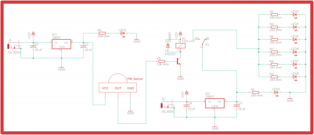
This is the regulated 5v power supply based on the LM7805 voltage regulator. This power supply will be used to power up the PIR Sensor Module. J1 is the dc female power jack. A 10uf capacitor is connected at the input side of the 7805 voltage regulator. Another 10uf capacitor is connected at the output side of the voltage regulator. A 330-ohm resistor is connected in series with a 2.5v led. This is a current limiting resistor.
A wire from the output of the voltage regulator is connected with the Vcc pin of the PIR sensor module, and also make sure you connect the ground of voltage regulator with the ground of the PIR Sensor module. The Out pin of the PIR sensor is connected with the base of the 2n2222 NPN transistor through a 10k resistor. the emitter of the 2n2222 NPN transistor is connected with the ground while the collector side is connected with one side of the relay coil and the relay coil other side is connected with the 12 volts.
This is another 5v regulated power supply the same as explained. This 5 volt will be used to power up the white color LEDs. This 5 volt is given to the LEDs through this relay. 330-ohm resistors are connected with the anode sides of all the Leds. While the cathode sides of all the LEDs are connected with the ground. When the PIR sensor detects any motion the relay is turned on, so the common pin of the relay will be connected with the normally open pin, which connects 5 volts with the anode side of the LEDs, and so the led’s will turned On.
The relay driver circuit simply consists of the 2n2222 NPN transistor and a 10k resistor.
Interfacing of street lights :
For the complete Model designing and making watch video Tutorial given at the end of this Article.
Watch Video Tutorial:

PIR related Project:
https://www.electroniclinic.com/how-to-make-motion-sensor-light-homemade-pir-light-sensor-automatic-light-switch/
https://www.electroniclinic.com/arduino-gsm-alarm-system/
https://www.electroniclinic.com/arduino-image-processing-cctv-camera-system/
Discover more from Electronic Clinic
Subscribe to get the latest posts sent to your email.