POWER AMPLIFIERS & AND THEIR SIMULATIONS
Last Updated on February 5, 2022 by Engr. Shahzada Fahad
Table of Contents
INTRODUCTION TO POWER AMPLIFIERS:-
Power Amplifiers- A power amplifier produces maximum power to drive a load (such as a loudspeaker) at a given distortion rate. It plays a pivotal role of “organization and coordination” in the whole sound system, which determines whether the whole system can provide good sound quality output to some extent.
Operational Principle
The power of the power supply is converted to the current that varies according to the input signal by current control of the triode or the voltage control of the field effect tube. Because sounds are waves of different amplitude and frequency, that is, the AC signal current. The collector current of the triode is always β times of the base current. If a small signal is injected into the base, the current flowing through the collector will be β times of that of the base, and then after the signal is isolated by a DC blocking capacitor, a large signal whose current (or voltage) is β times of those of the origin is generated, which is called the amplification effect of the triode. After continuous current amplification, power amplification is completed.
Major Classifications
Traditional digital voice playback systems consist of two main processes:
- …Transformation of digital voice data to analog voice signals (using high-precision digital-to-analog converter DAC).
- The process of using analog power amplifiers to amplify analog signal, such as Class A, Class B, and Class AB amplifiers. Since the early 1980s, many researchers have worked on the development of different types of digital amplifiers that directly perform power amplification from digital speech data without the need for analog conversion. Such amplifiers are commonly referred to as digital power amplifiers or class D amplifiers.
TO SIMULATE THE CLASS A AMPLIFIER AND CALCULATE THE EFFICIENCY
Objectives of CLASS A AMPLIFIER:-
- To simulate the class A amplifier.
- Calculate the efficiency.
- Observe the results.
Material Required for CLASS A AMPLIFIER:-
- Multisim Software (Updated Version )
- Input Ac power Source (V1=50mvp)
- Power supply (Vcc=24v)
- Transistor NPN (2N2222)
- 1 Resistor (100KΩ, 100KΩ, 100KΩ,300KΩ)
- Capacitors (10UF, 10UF)
- Connecting Wires
- Ground
- MS Word ( For writing down multiple observations)
Summary CLASS A AMPLIFIER:-
The most commonly used type of power amplifier configuration is the Class A Amplifier. The Class A amplifier is the simplest form of power amplifier that uses a single switching transistor in the standard common emitter circuit configuration as seen previously to produce an inverted output. The transistor is always biased “ON” so that it conducts during one complete cycle of the input signal waveform producing minimum distortion and maximum amplitude of the output signal.
…This means then that the Class A Amplifier configuration is the ideal operating mode, because there can be no crossover or switch-off distortion to the output waveform even during the negative half of the cycle. Class A power amplifier output stages may use a single power transistor or pairs of transistors connected together to share the high load current.
This is the simplest type of Class A power amplifier circuit. It uses a single-ended transistor for its output stage with the resistive load connected directly to the Collector terminal. When the transistor switches “ON” it sinks the output current through the Collector resulting in an inevitable voltage drop across the Emitter resistance thereby limiting the negative output capability.
The efficiency of this type of circuit is very low (less than 30%) and delivers small power outputs for a large drain on the DC power supply. A Class A amplifier stage passes the same load current even when no input signal is applied so large heat sinks are needed for the output transistors.
Power Amplifier Efficiency


Where η is the efficiency of the amplifier.
Pout is the amplifiers output power delivered to the load.
Pdc is the DC power taken from the supply.
Procedure For CLASS A AMPLIFIER Simulation:-
- Start by Opening the Multisim Software

- Appears A straight circuit window appears.

- Click “place” in the main menu <Properties <Select resistor <Set Value <Press OK.
- Place the Resistor in the region window and left Click to fix it.
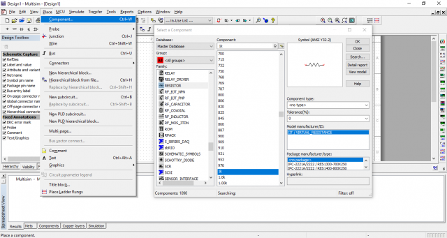
- Do the same for other things i.e. Resistor, Source Transistor, Ground capacitor etc.
- Them Place anywhere you click on the left to give them.
- Now After setting the required elements you bring the circuit close to the anchor material and fold it.
- Click Left on the first object pin, then left-click on the object pin to sharpen.
- Multisim will automatically insert the phone between the two selected elements
- Select the Ammeter and voltmeter from the menu and adjust it to the current acquisition cycle and the cutting edge.
- The cycle is ready now it analyzes the time setting. Save and use simulation.
Circuit diagram of CLASS A AMPLIFIER:-
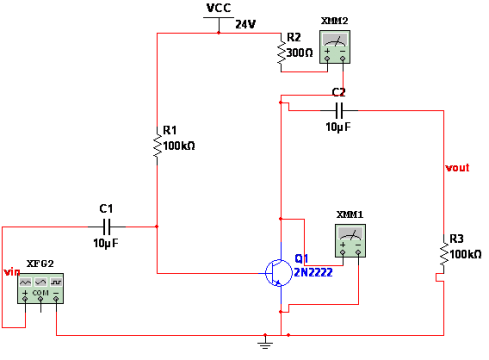
Simulation for CLASS A AMPLIFIER:-
Results of CLASS A AMPLIFIER:-
| Source (v) | P(ac) (i) watt | P(dc) watt (0) | η |
| 50 | 2Vcc 2 Ic | 8 vcc Ic | 50% |
| 50 | 2Vcc 2 Ic | 6 vcc Ic | 66.67% |
Impedance Matching of Class A Amplifier
Impedance matching can be done by making the output impedance of the amplifier equal to the input impedance of the load. This is an important principle for the transfer of maximum power (accordance with the maximum power transfer theorem).
Here the Impedance matching can be achieved by selecting the number of turns of the primary so that its net impedance is equal to the transistor output impedance and selecting the number of turns of the secondary so that its net impedance is equal to the loudspeaker input impedance.
Advantages of Class A Amplifier
- It has high fidelity because of the output exact replica of an input signal.
- It has improved high-frequency response because the active device is ON full time, i.e. no time is required to turn on the device.
- There is no crossover distortion because the active device conducts for the entire cycle of the input signal.
- The single ended configuration can be easily & practically realized in class A amp.
Disadvantages of Class A Amplifier
- Due to the large power supply and heat sink, class A amplifier is costly and bulky.
- It has Poor Efficiency.
- Due to the transformer coupling frequency response is not as good.
Applications of Class A Amplifier
The Class A Amplifier more suitable for outdoor musical systems, since the transistor reproduces the entire audio waveform without ever cutting off. As a result, the sound is very clear and more linear, that is, it contains much lower levels of distortion.
They are usually very large, heavy and they produce nearly 4-5 watts of heat energy per a watt of output. Therefore, they run very hot and need lots of ventilation. So they are not at all ideal for a car and rarely acceptable in a home.
Observations of CLASS A AMPLIFIER:-
By performing this lab I have observed and learned various things like
- It has high fidelity because of the output exact replica of an input signal.
- It has improved high-frequency response because the active device is ON full time, i.e. no time is required to turn on the device.
To simulate the Class B Complementary Symmetry Amplifier and calculate the efficiency.
Objectives of Class B Complementary Symmetry Amplifier:-
- To simulate the class B complementary symmetry amplifier.
- Calculate the efficiency.
- Observe the results.
Material Required for Class B Complementary Symmetry Amplifier:-
- Multisim Software (Updated Version )
- Input Ac power Source (Vcc=30vpk)
- Power supply (V1=30v)
- Power supply ( V2=30v)
- Transistor PNP (2N2907A)
- Transistor NPN (2N2222)
- 1 Resistor (1KΩ)
- Capacitors (100UF)
- Connecting Wires
- Ground
- MS Word ( For writing down multiple observations)
Summary of Class B Complementary Symmetry Amplifier:-
Class-B Amplifiers use two or more transistors biased in such a way so that each transistor only conducts during one half cycle of the input waveform.
To improve the full power efficiency of the previous Class A amplifier by reducing the wasted power in the form of heat, it is possible to design the power amplifier circuit with two transistors in its output stage producing what is commonly termed as a Class B Amplifier also known as a push-pull amplifier configuration.
Push-pull amplifiers use two “complementary” or matching transistors, one being an NPN-type and the other being a PNP-type with both power transistors receiving the same input signal together that is equal in magnitude, but in opposite phase to each other. This results in one transistor only amplifying one half or 180o of the input waveform cycle while the other transistor amplifies the other half or remaining 180o of the input waveform cycle with the resulting “two-halves” being put back together again at the output terminal.
Then the conduction angle for this type of amplifier circuit is only 180o or 50% of the input signal. This pushing and pulling effect of the alternating half cycles by the transistors gives this type of circuit its amusing “push-pull” name, but are more generally known as the Class B Amplifier. Class B Amplifier circuit that uses a balanced center-tapped input transformer, which splits the incoming waveform signal into two equal halves and which are 180o out of phase with each other.
A Class B amplifier is more efficient than a class A amplifier, which wastes half the energy due to it’s bias conditions. A Class A amplifier never turns off. A Class B amplifier turns off for the opposite pulse and is therefore more efficient.
However, unlike the Class A amplifier, it uses two active elements, typically transistors but in a bygone era were Vacuum tubes and is biased around a DC offset of zero.
This means that the waveform crosses from one active element to another. And since transistors don’t turn on in an ideal fashion (Silicon ones need 0.65 – 0.70 volts or so) this in turn leads to significant distortion – in fact it’s called crossover distortion. It is actually a phase distortion (if you choose to think of it like that).
Class B amps are usually used for high power applications. A good example is a PA system, for use in a club or large venue. The reason is because they are more efficient than a class A due to their ‘push/pull’ configuration. This is, however, arguably less desirable in situations that demand linear amplification. For this reason, you’re more likely to find class A amps in high end, recording, and audiophile equipment. However, it tends to be wildly more inefficient.
Applications
Class B push pull amplifiers actually operate in slightly Class AB to remove crossover distortion when one device changes conduction over to the other. Class B single ended RF Power amplifiers (single output device) also operate slightly above cutoff to eliminate distortion caused by non linearities. These represents the class for nearly all linear power amplifiers. Too low of idling, current moving the operation toward class B, will cause major distortion. Tubes and transistors of all types use this class. In class B power or motor control the distortion may not present a problem.
Class B amplifiers are greatly preferred over Class A designs for high-power applications such as audio power amplifiers and PA systems
An input signal waveform will cause the transistors to operate as normal in their active region thereby eliminating any crossover distortion present in pure Class B amplifier designs.
They used to be the standard in audio amplifiers and may still be used in cheap amplifiers, but they do suffer from crossover distortion. I believe they are still used as linear amplifiers in some RF applications – they used to be the standard there as well – the crossover distortion is not an issue and they handle AM and FM modulation well. With the wide availability of good power FETs they probably aren’t as popular.
| Class B | |
| Advantages | Disadvantages |
| Very low standing bias current. Negligible power consumption without signal. | Creates Crossover distortion. |
| Can be used for much more powerful outputs than class A | Supply current changes with signal, stabilized supply may be needed. |
| More efficient than Class A. | More distortion than Class A. |
Procedure of Class B Complementary Symmetry Amplifier:-
- Start by Opening the Multisim Software
- Appears A straight circuit window appears.
- Click “place” in the main menu <Properties <Select resistor <Set Value <Press OK.
- Place the Resistor in the region window and left Click to fix it.
- Do the same for other things i.e. Resistor, Source Transistor, Ground capacitor etc.
- Them Place anywhere you click on the left to give them.
- Now After setting the required elements you bring the circuit close to the anchor material and fold it.
- Click Left on the first object pin, then left-click on the object pin to sharpen.
- Multisim will automatically insert the phone between the two selected elements
- Select the Ammeter and voltmeter from the menu and adjust it to the current acquisition cycle and the cutting edge.
- The cycle is ready now it analyzes the time setting. Save and use simulatio
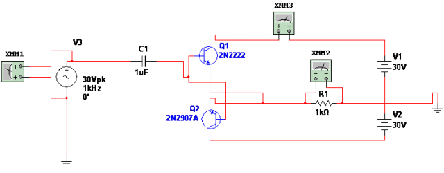
Circuit diagram of Class B Complementary Symmetry Amplifier:-
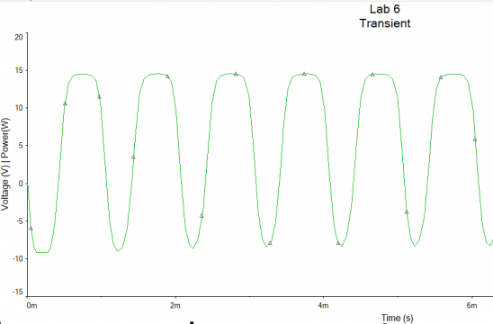
Simulations of Class B Complementary Symmetry Amplifier:-
Vcc Ic Vl (p-p)

Formulas of Class B Complementary Symmetry Amplifier:-
Pdc (i) = VCC (2IC (P) / π)
Pac (o) = (VL (P-P)) 2 / 8RL
η = (Pac (o) / Pdc (i)) X 100
Results of Class B Complementary Symmetry Amplifier:-
| Source (v) | P(dc) (i) watt | P(ac) watt (0) | η |
| 30 | 7070.9 p | 29.6m | 60 |
| 30 | 7107.4 p | 29.2m | 10 |
| 30 | 7008.0 p | 27.5m | 200 |
Observations of Class B Complementary Symmetry Amplifier:-
I have observed and learned various things like
- Some amount of distortion in the circuit gives the more output per device because of there is no presence of the even harmonics.
- The use of push-pull system in the class B amplifier eliminates the even harmonic.
Discover more from Electronic Clinic
Subscribe to get the latest posts sent to your email.