R557 Capacitive Fingerprint Sensor or Scanner with Arduino, Biometric Sensor
Biometric Door Lock using Arduino and R557 Fingerprint
Last Updated on September 21, 2024 by Engr. Shahzada Fahad
Table of Contents
R557 Capacitive Fingerprint Sensor:
R557 Capacitive Fingerprint Sensor or Scanner with Arduino, Biometric Sensor- In today’s article, I am going to use R557 3.3V Capacitive Fingerprint Module with Arduino to control an Electronic Door Lock.So, for this project, you will need an Arduino Uno or Arduino Nano, the R557 Capacitive Fingerprint Module, a 12V Electronic Door Lock, and a relay module.
Since this is a getting-started tutorial, so I am going to cover
- The R557 Fingerprint Module Technical specifications
- Its wiring details
- It’s circuit diagram
- How to enroll and manage new fingerprints?
- Arduino Programming and
- Practical testing.
So, without any further delay, let’s get started!!!
Amazon Links:
Arduino Nano USB-C Type (Recommended)
R557 Capacitive Fingerprint Module
*Disclosure: These are affiliate links. As an Amazon Associate I earn from qualifying purchases.
R557 Capacitive Fingerprint Sensor:
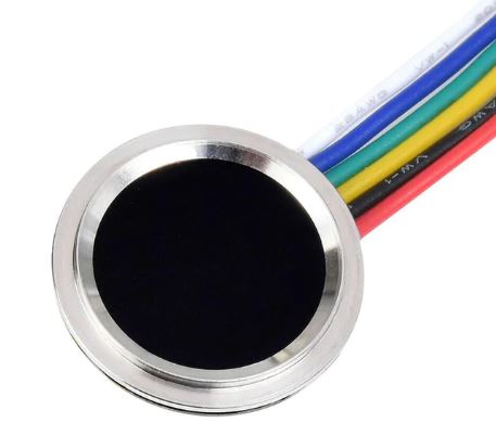
The R557 Fingerprint Sensor module is a compact and reliable biometric Sensor that can be used to secure doors or other access points. It can also be used in students and employees attendance systems. It’s a low-cost and low-power Fingerprint sensor. It operates on a low voltage of 3.3V, making it ideal for battery-powered systems. It can be used with 5v and 3.3V compatible controller boards like Arduino, ESP32, STM32, ESP8266, Raspberry Pi Pico, and so on. With this Capacitive Fingerprint sensor, you can easily integrate biometric authentication into your projects.
Technical specifications:
Technical parameter:
Supply voltage: DC 3.3V
Supply current:
Working current: 30mA (typ.)
Peak current: 40mA
Fingerprint image entry time: <0.3 seconds
Collection window area: 12.8mm in diameter
Image pixel: 160*160 pixel
Image Resolution: 508dpi
Match method:
Comparison method (1:1)
Search method (1:N)
Storage capacity: 120 pieces
Security level: five (from low to high: 1, 2, 3, 4, 5)
False Recognition Rate (FAR): <0.0001%
Authentic rejection rate (FRR): <1.0%
Search time: <0.3 seconds (1:1000, average)
Host computer interface: RS232 (TTL logic level, 3.3V)
Communication baud rate: (9600?N)bps where N=1~12 (default value N=6, ie 57600bps)
Working environment:
Temperature: -20 to +45?
Relative humidity: 10%RH-85%RH (non-condensing)
There is an RGB Led inside this module. So, when the fingerprint sensor is ON it shows Blue light. When the Fingerprint scanning operation is successful it shows Green Light, and when the operation is failed, it shows Red light.
It includes a storage capacity of up to 120 fingerprints, a fast recognition speed of under 1 second, and a high-resolution image sensor that captures clear and accurate fingerprints. For more technical specifications read my article available on www.electroniclinic.com.
R557 Capacitive Fingerprint Sensor Pinout:
Wiring
1 VT Finger detection
2 Out IRQ
3 VCC 3.3
4 TX 3.3 Logic level
5 RX 3.3 Logic level
6 GND
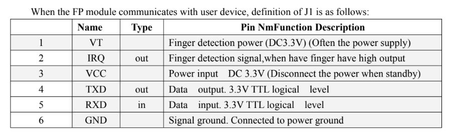
1st wire is the VT. This is the Finger Detection power and this wire is connected with the 3.3V.
2nd wire is the IRQ. This is the Finger detection signal wire. When there is a finger, it outputs a high signal.
3rd wire is the VCC and it should be connected with 3.3V.
4th and 5th wires are TXD and RXD, both are 3.3V TTL logical level. And
6th wire is the GND and it should be connected with the ground.
Now, let’s go ahead and take a look at the circuit diagram.
R557 Capacitive Fingerprint Sensor with Arduino:
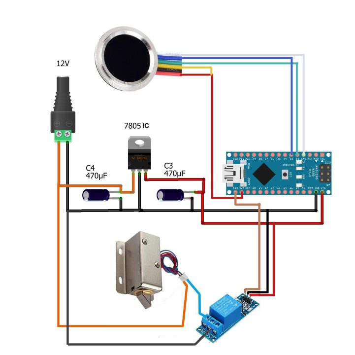
The VT and VCC wires of the R557 Capacitive Fingerprint sensor are connected with the Arduino 3.3V. The IRQ wire is left unconnected. The TXD and RXD wires are connected with the Arduino pins D2 and D3. And the ground wire is connected with the Arduino ground.
The one-channel Relay module is connected with the Arduino pin 13. And on the Left side is the 5V regulated power supply based on the Linear voltage regulator 7805.
Fingerprint Library Installation:
Now, the next step is to install the Arduino Library for the R557 Capacitive Fingerprint Sensor.
For this, open the Arduino IDE. Click on the sketch Menu, go to Include Library, and then click on manage libraries.

Search for the Adafruit Fingerprint.

Click on the install button.

You can see my Adafruit Fingerprint Sensor Library is now installed.
Next, for the Fingerprint enrollment connect your Arduino board with the Laptop/PC and Upload the following sketch into the Arduino Uno or Arduino Nano.
Fingerprint Enrollment Code:
|
1 2 3 4 5 6 7 8 9 10 11 12 13 14 15 16 17 18 19 20 21 22 23 24 25 26 27 28 29 30 31 32 33 34 35 36 37 38 39 40 41 42 43 44 45 46 47 48 49 50 51 52 53 54 55 56 57 58 59 60 61 62 63 64 65 66 67 68 69 70 71 72 73 74 75 76 77 78 79 80 81 82 83 84 85 86 87 88 89 90 91 92 93 94 95 96 97 98 99 100 101 102 103 104 105 106 107 108 109 110 111 112 113 114 115 116 117 118 119 120 121 122 123 124 125 126 127 128 129 130 131 132 133 134 135 136 137 138 139 140 141 142 143 144 145 146 147 148 149 150 151 152 153 154 155 156 157 158 159 160 161 162 163 164 165 166 167 168 169 170 171 172 173 174 175 176 177 178 179 180 181 182 183 184 185 186 187 188 189 190 191 192 193 194 195 196 197 198 199 200 201 202 203 204 205 206 207 208 209 210 |
#include <Adafruit_Fingerprint.h> #if (defined(__AVR__) || defined(ESP8266)) && !defined(__AVR_ATmega2560__) SoftwareSerial mySerial(2, 3); #else // On Leonardo/M0/etc, others with hardware serial, use hardware serial! // #0 is green wire, #1 is white #define mySerial Serial1 #endif Adafruit_Fingerprint finger = Adafruit_Fingerprint(&mySerial); uint8_t id; void setup() { Serial.begin(9600); while (!Serial); // For Yun/Leo/Micro/Zero/... delay(100); Serial.println("\n\nAdafruit Fingerprint sensor enrollment"); // set the data rate for the sensor serial port finger.begin(57600); if (finger.verifyPassword()) { Serial.println("Found fingerprint sensor!"); } else { Serial.println("Did not find fingerprint sensor :("); while (1) { delay(1); } } Serial.println(F("Reading sensor parameters")); finger.getParameters(); Serial.print(F("Status: 0x")); Serial.println(finger.status_reg, HEX); Serial.print(F("Sys ID: 0x")); Serial.println(finger.system_id, HEX); Serial.print(F("Capacity: ")); Serial.println(finger.capacity); Serial.print(F("Security level: ")); Serial.println(finger.security_level); Serial.print(F("Device address: ")); Serial.println(finger.device_addr, HEX); Serial.print(F("Packet len: ")); Serial.println(finger.packet_len); Serial.print(F("Baud rate: ")); Serial.println(finger.baud_rate); } uint8_t readnumber(void) { uint8_t num = 0; while (num == 0) { while (! Serial.available()); num = Serial.parseInt(); } return num; } void loop() // run over and over again { Serial.println("Ready to enroll a fingerprint!"); Serial.println("Please type in the ID # (from 1 to 127) you want to save this finger as..."); id = readnumber(); if (id == 0) {// ID #0 not allowed, try again! return; } Serial.print("Enrolling ID #"); Serial.println(id); while (! getFingerprintEnroll() ); } uint8_t getFingerprintEnroll() { int p = -1; Serial.print("Waiting for valid finger to enroll as #"); Serial.println(id); while (p != FINGERPRINT_OK) { p = finger.getImage(); switch (p) { case FINGERPRINT_OK: Serial.println("Image taken"); break; case FINGERPRINT_NOFINGER: Serial.println("."); break; case FINGERPRINT_PACKETRECIEVEERR: Serial.println("Communication error"); break; case FINGERPRINT_IMAGEFAIL: Serial.println("Imaging error"); break; default: Serial.println("Unknown error"); break; } } // OK success! p = finger.image2Tz(1); switch (p) { case FINGERPRINT_OK: Serial.println("Image converted"); break; case FINGERPRINT_IMAGEMESS: Serial.println("Image too messy"); return p; case FINGERPRINT_PACKETRECIEVEERR: Serial.println("Communication error"); return p; case FINGERPRINT_FEATUREFAIL: Serial.println("Could not find fingerprint features"); return p; case FINGERPRINT_INVALIDIMAGE: Serial.println("Could not find fingerprint features"); return p; default: Serial.println("Unknown error"); return p; } Serial.println("Remove finger"); delay(2000); p = 0; while (p != FINGERPRINT_NOFINGER) { p = finger.getImage(); } Serial.print("ID "); Serial.println(id); p = -1; Serial.println("Place same finger again"); while (p != FINGERPRINT_OK) { p = finger.getImage(); switch (p) { case FINGERPRINT_OK: Serial.println("Image taken"); break; case FINGERPRINT_NOFINGER: Serial.print("."); break; case FINGERPRINT_PACKETRECIEVEERR: Serial.println("Communication error"); break; case FINGERPRINT_IMAGEFAIL: Serial.println("Imaging error"); break; default: Serial.println("Unknown error"); break; } } // OK success! p = finger.image2Tz(2); switch (p) { case FINGERPRINT_OK: Serial.println("Image converted"); break; case FINGERPRINT_IMAGEMESS: Serial.println("Image too messy"); return p; case FINGERPRINT_PACKETRECIEVEERR: Serial.println("Communication error"); return p; case FINGERPRINT_FEATUREFAIL: Serial.println("Could not find fingerprint features"); return p; case FINGERPRINT_INVALIDIMAGE: Serial.println("Could not find fingerprint features"); return p; default: Serial.println("Unknown error"); return p; } // OK converted! Serial.print("Creating model for #"); Serial.println(id); p = finger.createModel(); if (p == FINGERPRINT_OK) { Serial.println("Prints matched!"); } else if (p == FINGERPRINT_PACKETRECIEVEERR) { Serial.println("Communication error"); return p; } else if (p == FINGERPRINT_ENROLLMISMATCH) { Serial.println("Fingerprints did not match"); return p; } else { Serial.println("Unknown error"); return p; } Serial.print("ID "); Serial.println(id); p = finger.storeModel(id); if (p == FINGERPRINT_OK) { Serial.println("Stored!"); } else if (p == FINGERPRINT_PACKETRECIEVEERR) { Serial.println("Communication error"); return p; } else if (p == FINGERPRINT_BADLOCATION) { Serial.println("Could not store in that location"); return p; } else if (p == FINGERPRINT_FLASHERR) { Serial.println("Error writing to flash"); return p; } else { Serial.println("Unknown error"); return p; } return true; } |
After uploading this code; next open the serial monitor and follow the instructions. If you find it difficult to enroll your fingers then you can follow my video tutorial given at the end of this article. Anyway, I enrolled two fingers “the forefinger and the middle finger” I assigned 3 as an ID to the forefinger and 4 as an to my Middle finger.
After, enrolling all your fingers. Next, download the following code, and replace my finger ids with yours.
Capacitive Fingerprint Sensor Final Code:
|
1 2 3 4 5 6 7 8 9 10 11 12 13 14 15 16 17 18 19 20 21 22 23 24 25 26 27 28 29 30 31 32 33 34 35 36 37 38 39 40 41 42 43 44 45 46 47 48 49 50 51 52 53 54 55 56 57 58 59 60 61 62 63 64 65 66 67 68 69 70 71 72 73 74 75 76 77 78 79 80 81 82 83 84 85 86 87 88 89 90 91 92 93 94 95 96 97 98 99 100 101 102 103 104 105 106 107 108 109 110 111 112 113 114 115 116 117 118 119 120 121 122 123 124 125 126 127 128 129 130 131 132 133 134 135 136 137 138 139 140 141 142 143 144 145 146 147 148 149 150 151 152 153 154 155 156 157 158 159 160 |
#include <Adafruit_Fingerprint.h> int relay=13; #if (defined(__AVR__) || defined(ESP8266)) && !defined(__AVR_ATmega2560__) SoftwareSerial mySerial(2, 3); #else // On Leonardo/M0/etc, others with hardware serial, use hardware serial! // #0 is green wire, #1 is white #define mySerial Serial1 #endif Adafruit_Fingerprint finger = Adafruit_Fingerprint(&mySerial); void setup() { pinMode(relay,OUTPUT); Serial.begin(9600); while (!Serial); // For Yun/Leo/Micro/Zero/... delay(100); Serial.println("\n\nAdafruit finger detect test"); // set the data rate for the sensor serial port finger.begin(57600); delay(5); if (finger.verifyPassword()) { Serial.println("Found fingerprint sensor!"); } else { Serial.println("Did not find fingerprint sensor :("); while (1) { delay(1); } } Serial.println(F("Reading sensor parameters")); finger.getParameters(); Serial.print(F("Status: 0x")); Serial.println(finger.status_reg, HEX); Serial.print(F("Sys ID: 0x")); Serial.println(finger.system_id, HEX); Serial.print(F("Capacity: ")); Serial.println(finger.capacity); Serial.print(F("Security level: ")); Serial.println(finger.security_level); Serial.print(F("Device address: ")); Serial.println(finger.device_addr, HEX); Serial.print(F("Packet len: ")); Serial.println(finger.packet_len); Serial.print(F("Baud rate: ")); Serial.println(finger.baud_rate); finger.getTemplateCount(); if (finger.templateCount == 0) { Serial.print("Sensor doesn't contain any fingerprint data. Please run the 'enroll' example."); } else { Serial.println("Waiting for valid finger..."); Serial.print("Sensor contains "); Serial.print(finger.templateCount); Serial.println(" templates"); } } void loop() // run over and over again { getFingerprintID(); delay(50); //don't ned to run this at full speed. } uint8_t getFingerprintID() { uint8_t p = finger.getImage(); switch (p) { case FINGERPRINT_OK: Serial.println("Image taken"); break; case FINGERPRINT_NOFINGER: //Serial.println("No finger detected"); ; finger.LEDcontrol(FINGERPRINT_LED_OFF, 0, FINGERPRINT_LED_BLUE); finger.LEDcontrol(FINGERPRINT_LED_OFF, 0, FINGERPRINT_LED_RED); return p; case FINGERPRINT_PACKETRECIEVEERR: Serial.println("Communication error"); return p; case FINGERPRINT_IMAGEFAIL: Serial.println("Imaging error"); return p; default: Serial.println("Unknown error"); return p; } // OK success! p = finger.image2Tz(); switch (p) { case FINGERPRINT_OK: Serial.println("Image converted"); break; case FINGERPRINT_IMAGEMESS: Serial.println("Image too messy"); return p; case FINGERPRINT_PACKETRECIEVEERR: Serial.println("Communication error"); return p; case FINGERPRINT_FEATUREFAIL: Serial.println("Could not find fingerprint features"); return p; case FINGERPRINT_INVALIDIMAGE: Serial.println("Could not find fingerprint features"); return p; default: Serial.println("Unknown error"); return p; } // OK converted! p = finger.fingerSearch(); if (p == FINGERPRINT_OK) { Serial.println("Found a print match!"); finger.LEDcontrol(FINGERPRINT_LED_FLASHING, 25, FINGERPRINT_LED_PURPLE, 10); delay(1000); } else if (p == FINGERPRINT_PACKETRECIEVEERR) { Serial.println("Communication error"); return p; } else if (p == FINGERPRINT_NOTFOUND) { finger.LEDcontrol(FINGERPRINT_LED_FLASHING, 25, FINGERPRINT_LED_RED, 10); delay(1000); Serial.println("Did not find a match"); return p; } else { Serial.println("Unknown error"); return p; } // found a match! Serial.print("Found ID #"); Serial.print(finger.fingerID); Serial.print(" with confidence of "); Serial.println(finger.confidence); if (finger.fingerID == 3 ) // 3 is the ID of the fore finger digitalWrite(relay, HIGH); if (finger.fingerID == 4) // 4 is the ID of Middle finger digitalWrite(relay, LOW); return finger.fingerID; } // returns -1 if failed, otherwise returns ID # int getFingerprintIDez() { uint8_t p = finger.getImage(); if (p != FINGERPRINT_OK) return -1; p = finger.image2Tz(); if (p != FINGERPRINT_OK) return -1; p = finger.fingerFastSearch(); if (p != FINGERPRINT_OK) return -1; // found a match! Serial.print("Found ID #"); Serial.print(finger.fingerID); Serial.print(" with confidence of "); Serial.println(finger.confidence); return finger.fingerID; } |
This is the Final Code that I use to lock and unclock the Electronic Door Lock. Let me show you how I used the IDs.
If finger.fingerID == 3 then open the lock. And if you remember 3 is the ID of my forefinger. And similarly, if finger.fingerID == 4 then close the electronic lock. And you know 4 is the ID of my middle finger.
I have already uploaded this program and now let’s watch this Capacitive Fingerprint sensor and Electronic Lock in action.
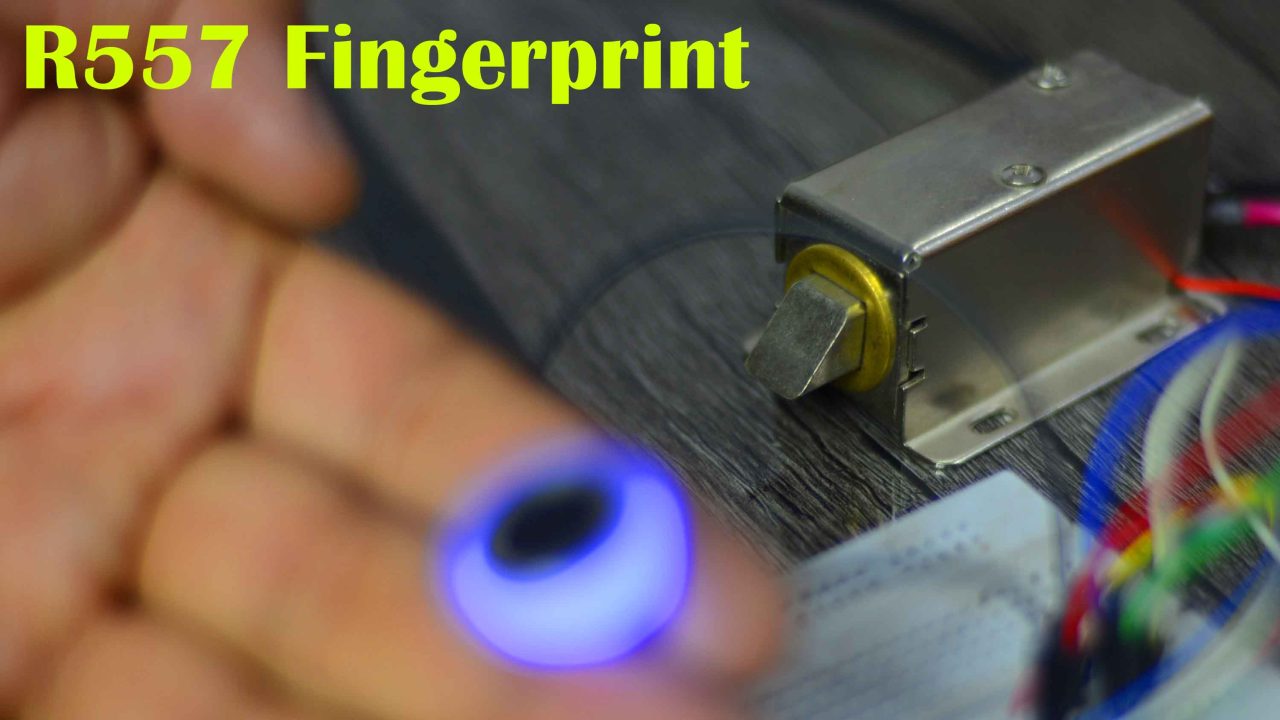
Blue light means the sensor is ON and you can place your finger. Right now, you can see the Lock is closed.
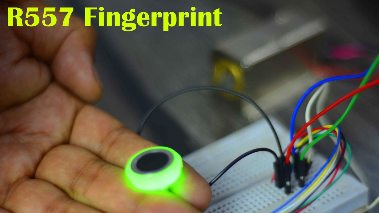
The green color means the finger is successfully scanned and you can see the Electronic Door lock is unlocked. If you see the Red color then it means you are scanning the wrong finger. For the practical demonstration watch the video tutorial given below.
With its low power consumption, fast recognition speed, and easy-to-use software, it is a great choice for both hobbyists and professionals. So, that’s all for now.
Watch Video Tutorial:

Discover more from Electronic Clinic
Subscribe to get the latest posts sent to your email.


Thank you for the amazing tutorial. I want to connect two fingerprint sensors to the same hardware serial. And when I use one sensor, the other would be inactive anyway, so it won’t interfere with the setup and should behave like your demonstration. I can not get it to work. Could you help me modify the code to get that to work? Thank you very much