Relay H Bridge Driver Circuit, Simulation, and Arduino Programming
Last Updated on August 18, 2024 by Engr. Shahzada Fahad
Table of Contents
Relay H-bridge Designing, Description:
Relay H Bridge Driver Circuit, Simulation, and Arduino Programming- In this tutorial, you will learn how to design and make your own Relay H Bridge to control a DC Motor. If you only need the circuit diagram and programming then you can jump to the circuit diagram and programming section, but trust me this will never help you learn the designing. If you really want to learn how to design something from scratch when there is nothing. This is the only tutorial throughout the world which explains the designing steps from nothing to the final working product.
In this tutorial, we will cover,
- What is an H bridge?
- How to start designing the Relay H Bridge?
- About the Relay
- Relay H Bridge circuit diagram
- Relay H Bridge Proteus Simulation
- Relay H Bridge PCB designing
- Relay H Bridge Arduino Programming
- Relay H Bridge Practical Demonstration
Without any further delay, let’s get started!!!
Amazon Links:
Arduino Nano USB-C Type (Recommended)
*Disclosure: These are affiliate links. As an Amazon Associate I earn from qualifying purchases.
What is any H-Bridge?
The H-Bridge is basically an electronic circuit that is used to change the polarity of the voltage applied to the load. H-bridges are most commonly used in robotics for the Forward, Left, Right, and Reverse Movement. H bridges are also used in industries to Allow High Ampere DC Motors to run Forward and backward.
As slowly and gradually we start understanding the H Bridge and its uses, some questions start to pop up in our minds like for example the most basic question that you also might be thinking about is,
Why H is used?
What does it mean?
The term H Bridge is actually the typical graphical representation of the circuit. Let me explain this in very simple words, the term H Bridge is derived from the flow of current in the circuit which you will understand completely with the help of the following example. An H bridge can be build using four switches, Mosfets or Relays.
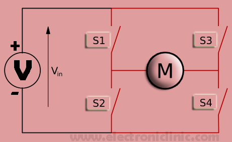
The switches S1, S2, S3, and S4 are used to change the polarity of the voltage supplied to the DC Motor. When the switches, S1 and S4 are closed. The flow of current can be seen in the picture below.
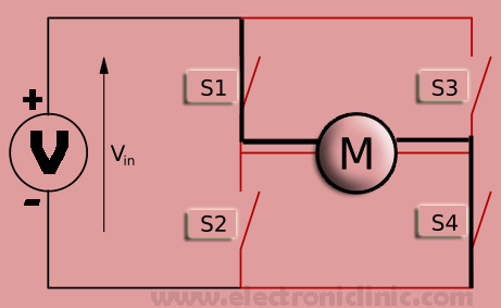
The left terminal of the motor is connected with the Voltage while the right side is connected with the ground.
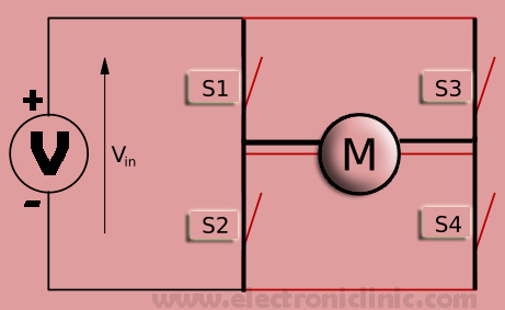
Now if the switches S2 and S3 are closed.
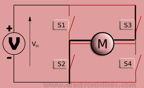
Now you can see the right terminal of the motor is connected with the Voltage while the left terminal of the motor is connected with the ground. This is how the H Bridge works. Now if the above two images are combines you will see it makes H. That’s why it is called an H Bridge.
So I hope now you have a basic understanding of what is an h bridge and how it works.
One thing that you should always take care off switches S1 and S2 should never be closed “Turned ON” both at the same time and similarly for S3 and S4. If you do so it will short the voltage and ground. This applies only when you use 4 switches.
As this tutorial is about the relay h bridge so I will now talk about the relays only. We can use 4 relays to control the polarity of the voltage which is supplied to the DC Motor, but as I said using 4 switches or relays there is high risk when the switches S1 and S2 or turned On both at the same time, which results in the short circuit. The same can happen with the relays or switches S3 and S4.
To get rid of this risk we can also make an H bridge using only two relays. So this way no matter which relay you turn on first or you turn ON both the relays at the same time, there will be no short circuit. So now we will start designing the H bridge relay circuit using only two relays.
For the relays based H Bridge, you should have complete knowledge of the Relay and its pins. You should know exactly which are the normally closed and normally open legs, which are the legs of the coil and which is the common leg. For the best designing, you need to know about each and every detail.
About the Relay:
Every Person nowadays is familiar with the term Relay; relays are most commonly used for switching purposes and are also used for protection. The relay switching operation can be manual or automatic depending on the use. The manual operation makes use of the pushbuttons or other conventional switches available in the market. But mostly relays are used in automatic operations.
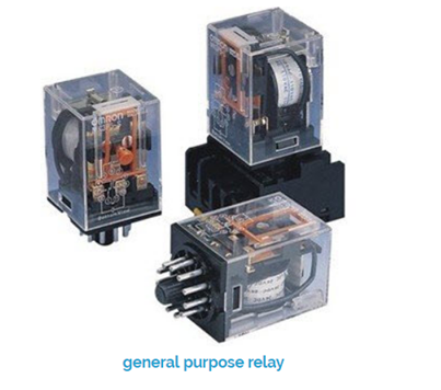
Relay is an Electromechanical Device which has mechanical components like spring, contacts and a coil. The Relay works just like an ordinary switch but the only difference is that it can be controlled automatically through a signal. A relay can control a circuit, device, machine, etc by opening or closing the relay contacts. Basic Construction of all the electromechanical relays is same it has coil pins to energize the relay coil, common terminal “com”, Normal Open (“NO”) contact and normally closed “NC” contact. These contacts are either open or closed when the relay is in operation.
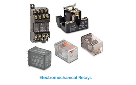
If we look at relays we will know that all relays are actually working on the principle of electromagnetic attraction. The EMF electromagnetic force which is experienced on the Plunger or the armature is proportional to the Square of magnetic flux in the air gap or square of the current. Relays can be classified into hinged armature type, balanced beam type, moving coil type, plunger type, and reed type relays.
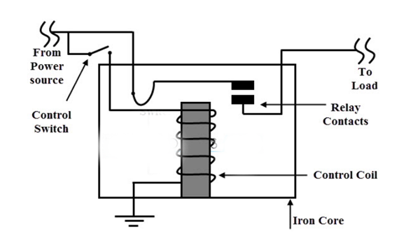
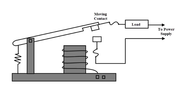
Relay Operation
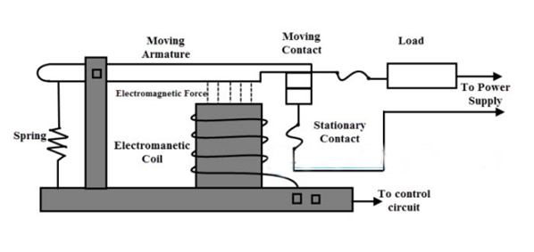
The relay operation is illustrated in the figures below. If we take any type of Electromechanical relay we will see that its major components are Armature, coil, and Contacts. A wire of certain gauge is wound on the magnetic core which makes an electromagnet. When supply is connected with the relay coil, the coil energizes and produces an electromagnetic field. The armature is actually a movable part of the relay and its function is to open and close the relay contacts, it is connected with the spring so that when no voltage is supplied to the relay coil it comes back to its default position. While the Contacts are conducting parts of the relay which connects the load and source circuits, these are the contacts which are damaged due to the arc phenomena.
Under Energized Condition
If the relay coil is connected with the desired voltage source, the coil of the relay will be energized and produces the magnetic flux which is proportional to the current flowing through it. This magnetic field causes the contact to move “this is the common contact of the relay” so the common contact of the relay gets connected with the normally open contact.
Under De-energized Condition:
When the power is disconnected from the relay coil, there is no magnetic flux production so the armature remains at its original position. As a result, there exists a very small air gap between the relay contacts. So in this situation, the NC contact of the relay is always connected with the common contact of the relay. That’s why it is called normally closed contact.
Relay Contact Types
Relays are available in different sizes, styles, configurations, and technologies. Depends on the suitability and application of the relay. Most importantly a relay has three contacts which are most important these contacts are common, normally closed and normally open. We usually talk about the relay in terms of poles and throws.
Poles and Throws
Depending on the number of poles and throws, relays are divided into the following 4 categories.
- Single pole single throw “SPST”
- Single pole double throw” SPDT”
- Double pole single throw” DPST”
- Double pole double throw” DPDT”
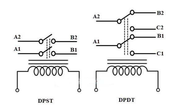
The below figure shows different types of relays based on their switching contacts. A single pole single throw relay which is normally known as the SPDT relay can control only one circuit and can be connected to only one output. It is used in an electrical system where we need to only turn ON or Turn OFF any electrical load, or it is used to signal a microcontroller. A single pole double throw relay connects one input circuit to one of the two outputs which are normally closed and normally open contacts.
A DPST “double pole single throw” relay has two poles and has a single throw and are most commonly used to connect two terminals of a single circuit at a time. For example, such type of relay can be used to connect both the phase and neutral terminals to the load at the same time.
A DPDT stands for “double pole double throw” this type of relay has two poles and two throws for each pole. With the help of these relays we can easily control the direction of motors, can be used for phase or polarity reversal. The Switching between the contacts depends on the coil when energized. For automatic operations, relay design calculations are performed to find the current needed to energize the relay.
Normally Open and Normally Closed Contacts
A normally open type relay indicates that the switch is open when the relay coil is demagnetized or de-energized, this condition happens only when the supply voltage is not connected with the relay coil. The following figures show the normally open, close and contacts changeover.
Whenever the relay coil is connected with a supply voltage, the relay coil is energized and makes a magnet. Then this magnet attracts the common contact of the relay to get connected with another contact to make a closed circuit. In case of the SPDT type relay, the normally open become close and the normally closed becomes open. So this way a relay can be made to switch another circuit ON or OFF.

Driving a Relay
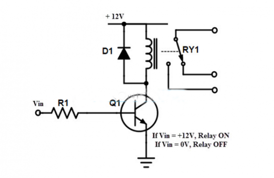
Relays can be controlled through a low voltage signal and can be used to control a high power circuit with a lower power circuit. To make a relay Operate, first of all, we will have to energize the relay coil by simply passing the current through the relay coil. Most of the relays which are available in the market are 12v and 24v. I will be using a 12v relay. 12v relay cannot be directly controlled by the controller, that’s why electromechanical relay needs a driver circuit. A driver circuit simply consists of an NPN or PNP type transistor and a resistor. Depends on the designer whether he/she wants to use the PNP or NPN. I will be using an NPN transistor in my Proteus simulation.
For the Driver circuit to design, first of all, we find the relay coil resistance using a digital multimeter. The relay voltage is already known which is 12v. then by using the Ohm’s law
V = IR
We can find the current, which will be needed to energize the relay coil to make enough magnet to attract the contact. After finding the relay coil current then select any general NPN type transistor whose collector current is greater than the relay coil current. In my case, I will use 2n2222 type transistor because it is cheap, easily available in the market and moreover it can handle much more current than the calculated value which was 32ma.
A 10k resistor is connected with the base of the 2n2222 NPN transistor as it’s a BJT bipolar junction transistor and it’s a current-controlled device so that’s why a 10k resistor must be added to limit the current. Then we get the below circuit. Through this circuit, we can control an electromechanical relay through a microcontroller.
Relay Applications
- Lighting control systems
- Telecommunication
- Industrial process controllers
- Traffic control
- Motor drives control
- Protection systems of electrical power system
- Computer interfaces
- Automotive
- Home appliances
Relays based H bridge advantage:
- Gives perfect Isolation between the controlling circuit and Motor external Power Supply.
- Costs you less amount of money as compared to Mosfets based h bridges.
- Almost no conduction losses.
- Based on relays extremely high powerful h bridges can be designed.
- Low short circuit risk.
- Easy maintenance
Relays based H Bridges also have some disadvantages which are they don’t support PWM. But this problem can be solved by adding an external variable power supply.
So now that I have covered all the basics, now it’s time to discuss the circuit diagram and after that, I will make a simulation to check if my designing really works; before I start the Arduino Programming.
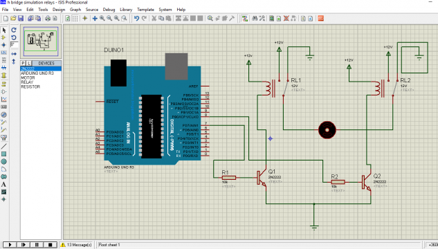
Relay H Bridge Circuit Diagram:
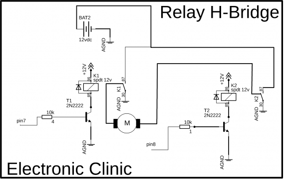
Normally open contacts of both the relays are connected together and are connected with the 12v External Power supply +Ve terminal. Similarly, the Normally closed contacts of both the relays are connected together and are connected with the Ground of the External Power supply.
One side of the relay coil is connected with the +12 volts while the other side of the relay coil is connected with the collector of the 2n2222 NPN transistor. The emitters of both the relays are connected with the ground. 10K resistors are connected with the bases of both the 2n2222 NPN transistors. Each relay can be controlled using 5 volts. This 5 volts can be provided by the Arduino or any other microcontroller. If you turn on one relay and the other relay remains off the motor rotate in one direction and vice versa. Now let’s check this circuit in Proteus for this we will need a program to control the H Bridge.
Relay H Bridge Arduino Proteus Simulation:
Relay H Bridge Arduino Programming:
|
1 2 3 4 5 6 7 8 9 10 11 12 13 14 15 16 17 18 19 20 21 22 23 24 25 26 27 28 29 30 |
int relay1 = 7; int relay2 = 8; void setup() { pinMode(relay1, OUTPUT); pinMode(relay2, OUTPUT); digitalWrite(relay1, LOW); digitalWrite(relay2, LOW); } void loop() { digitalWrite(relay1, HIGH); digitalWrite(relay2, LOW); delay(1000); digitalWrite(relay1, LOW); digitalWrite(relay2, LOW); delay(1000); digitalWrite(relay1, LOW); digitalWrite(relay2, HIGH); delay(1000); digitalWrite(relay1, LOW); digitalWrite(relay2, LOW); delay(1000); } |
Program explanation:
This is a very basic program written for controlling the direction of a dc motor. the purpose of this program is to rotate the motor in one direction, then stops the motor for 1 second, then rotate the motor in another direction, then again stops the motor for one second and then this cycle is repeated again and again.
As we are using two relays for controlling the motor direction, so we start by defining two pins for the relays.
int relay1 = 7; // relay1 is connected with pin7 of the Arduino
int relay2 = 8; // relay2 is connected with pin8 of the Arduino
Every Arduino and the mega program has at least two functions, which are void setup() and void loop(). Void setup() runs only one time when the Arduino Uno or Mega board is powered up.
Void means that this function is not returning any value and the empty parenthesis means that this function is not returning any value.
void setup()
{
pinMode is a function and takes two arguments as the input, which are the pin number or pin name, and the status which can be input or output, as we are using a relay to control the dc motor so over here the relay is an output device. So that’s why set it as output.
pinMode(relay1, OUTPUT);
pinMode(relay2, OUTPUT);
digitalWrite(relay1, LOW);
digitalWrite(relay2, LOW);
digitalWrite is a function and is used to turn on or turn off any pin of the Arduino Uno or mega. So the purpose of these two instructions is to keep both the relays in the off state when the Arduino or mega board is powered up.
}
then starts a void loop function, this functions runs infinite times.
void loop()
{
to rotate the motor in one direction, we turn on the relay1 while relay2 remains in off state.
digitalWrite(relay1, HIGH);
digitalWrite(relay2, LOW);
then there is a delay of 1000 milli seconds which is equal to 1 second.
delay(1000);
then we turn off the motor
digitalWrite(relay1, LOW);
digitalWrite(relay2, LOW);
again a delay of 1 second
delay(1000);
then relay1 remains in off state and the relay2 is turned on, now the motor will rotate in another direction. and so on…
digitalWrite(relay1, LOW);
digitalWrite(relay2, HIGH);
delay(1000);
digitalWrite(relay1, LOW);
digitalWrite(relay2, LOW);
delay(1000);
}
After you are done with the programming, generate the hex file, copy the link and paste it in the Proteus simulation and then press the play button.
Watch the Relay H Bridge Simulation Video:
Relay H Bridge PCB designing:
So now that I am satisfied with the circuit and its working perfectly. Now it’s time to design the PCB. Now it’s difficult to explain all the PCB designing steps because the tutorial is already too long. But no worries I have a very detailed tutorial on how to design your own schematic and PCB. You can find this video in the related projects section.
Following is the picture of the Relay H-bridge:
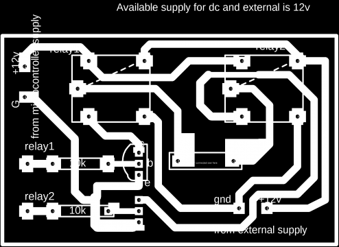
Download the Relay H Bridge PCB board file: relay hbridge
This file will open in the latest version of the cadsoft Eagle.
For the soldering watch video given below. Check the related projects sections given below where you can find some projects in which the same H Bridge Module is used.
Watch Video Tutorial:
Discover more from Electronic Clinic
Subscribe to get the latest posts sent to your email.


