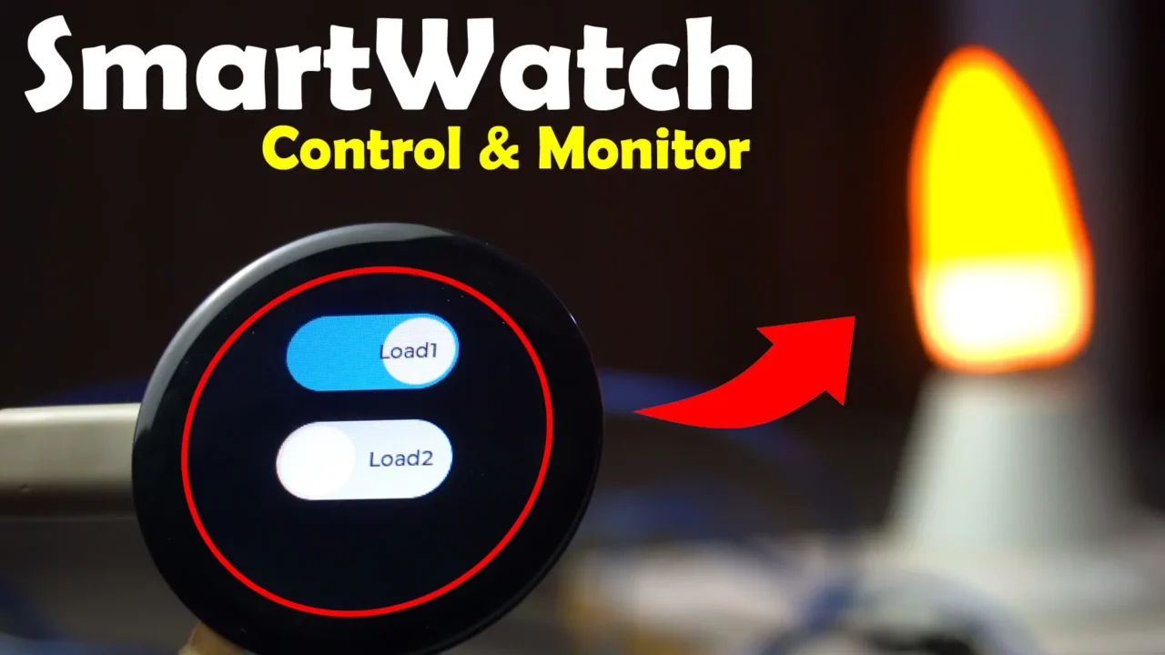
SmartWatch Home Automation and Sensor Monitoring
Last Updated on March 18, 2025 by Engr. Shahzada Fahad
Table of Contents
Smartwatch Home Automation:
SmartWatch Home Automation and Sensor Monitoring- Now you can use a smartwatch to not only control your entire house but also monitor different types of sensors. And the best part is, you can do this from anywhere in the world by using the Ubidots IoT Cloud Platform, which connects the smartwatch to the device you want to control. Before we start this project, I want to share a few things with you because this project is a bit advanced.
This is my 8th article in the Smartwatch programming series and throughout this series I used the CrowPanel ESP32C3 1.28 Inch IPS Capacitive Touch Display.
If you have already used SquareLine Studio and Ubidots, then you won’t have any trouble understanding this project. But if you don’t know what SquareLine Studio and Ubidots are, then you will need to read my previous articles first.
Because you need to know how to install the ESP32 board in Arduino IDE, which libraries to install for the CrowPanel display, which version of the LVGL library to use with SquareLine Studio, how to fix basic errors, and which libraries to install for Ubidots. I have already explained all of this in my previous articles and videos, so I won’t repeat it again.
Amazon Links:
ESP32 WiFi + Bluetooth Module (Recommended)
Other Tools and Components:
Arduino Nano USB C type (Recommended)
*Please Note: These are affiliate links. I may make a commission if you buy the components through these links. I would appreciate your support in this way!
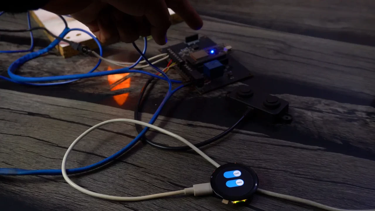
Smartwatch Home Automation Hardware:
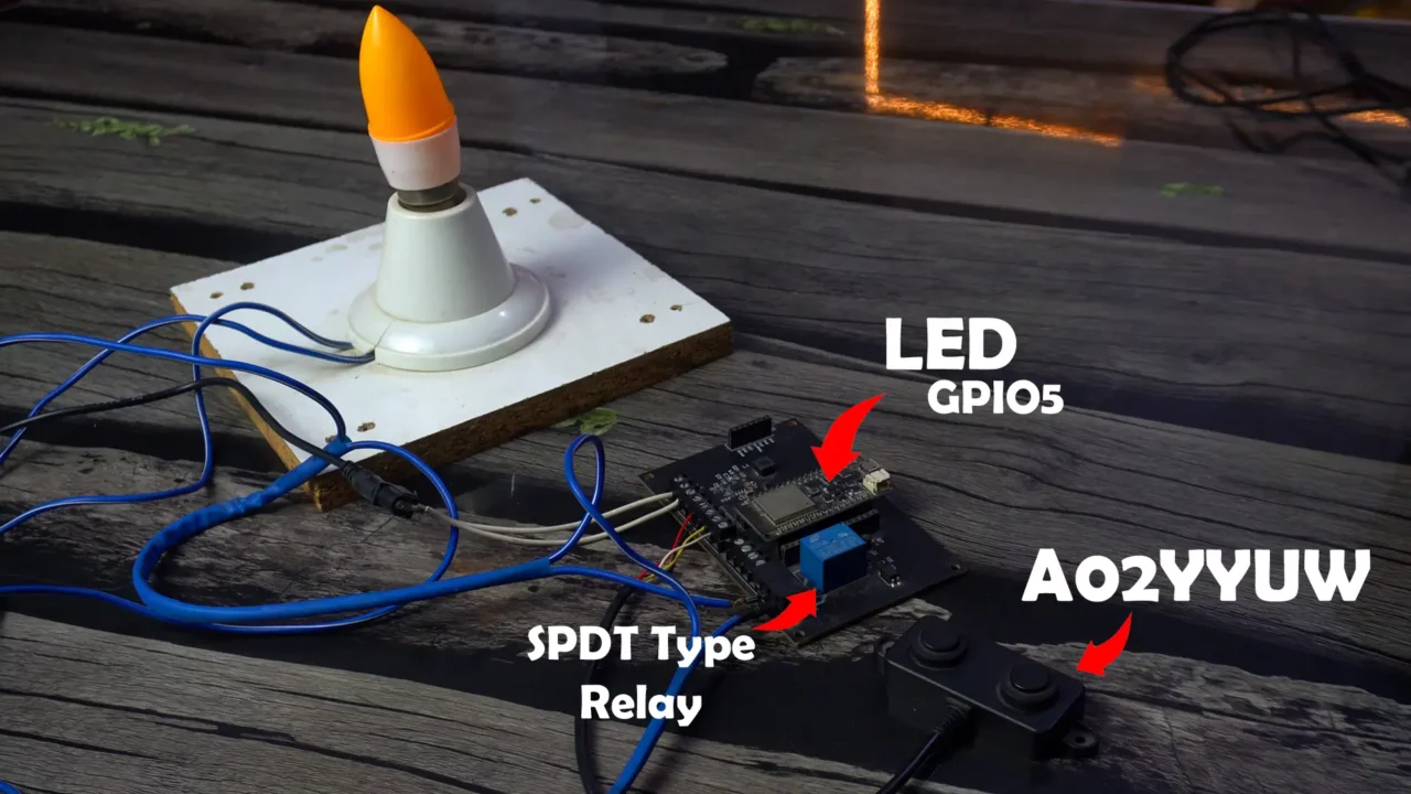
Anyway, this is my setup from the previous home automation project, which focused on controlling a single load using a 5V SPDT type relay. The bulb from that project is still connected to the relay, functioning as one of the primary loads. However, this time, I have added a new component to enhance the system’s functionality; a waterproof ultrasonic sensor, the A02YYUW. This sensor brings additional possibilities for detecting objects or measuring distances, which can be integrated into various automation scenarios.
Along with controlling the bulb via the relay, we will also control the onboard LED, which is connected to GPIO5 on the ESP32. By including the LED as a secondary load, this setup demonstrates how to manage multiple outputs simultaneously, making it an excellent example for those looking to expand their automation projects.
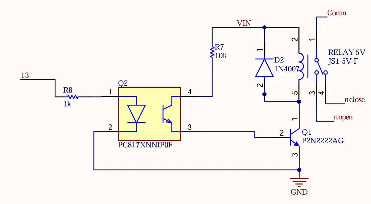
For the Relay connections you can follow this circuit diagram
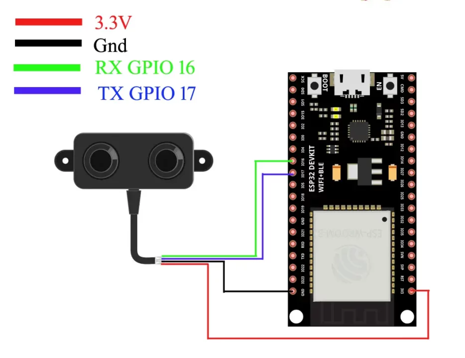
And for the A02YYUW Waterproof Ultrasonic sensor wiring; you can follow this circuit diagram.
Now, let’s first start with the SquareLine Studio.
SquareLine studio GUI:
How to start a new project, how to use widgets, how to change screens, how to call functions, and how to generate UI files, etc., have already been explained in Part 2 “Counter Project”.
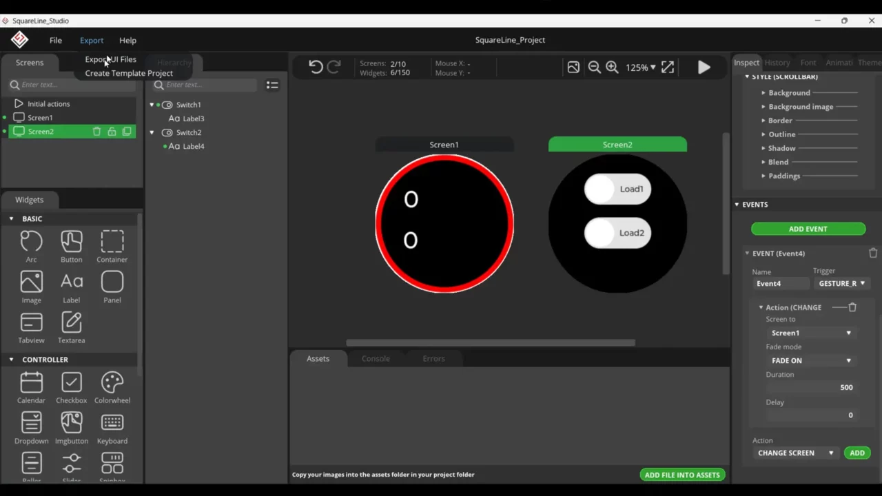
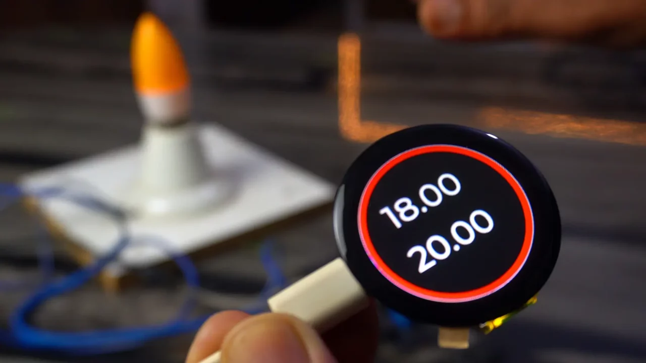
It’s just a simple GUI, On Screen1 I have added two Labels for displaying the Sensor1 and Sensor2 values.
On Screen2, I have added two switches to controlling the 110/220Vac Bulb and the ESP32 onboard LED.
I have added to events with the names load1control and load2control.
And finally, I added the Change Screen events to switch between the two screens and then go ahead save the project and export the UI files. If in case you face any difficult then you can watch the video tutorial given at the end of this article.
Smartwatch Code:
|
1 2 3 4 5 6 7 8 9 10 11 12 13 14 15 16 17 18 19 20 21 22 23 24 25 26 27 28 29 30 31 32 33 34 35 36 37 38 39 40 41 42 43 44 45 46 47 48 49 50 51 52 53 54 55 56 57 58 59 60 61 62 63 64 65 66 67 68 69 70 71 72 73 74 75 76 77 78 79 80 81 82 83 84 85 86 87 88 89 90 91 92 93 94 95 96 97 98 99 100 101 102 103 104 105 106 107 108 109 110 111 112 113 114 115 116 117 118 119 120 121 122 123 124 125 126 127 128 129 130 131 132 133 134 135 136 137 138 139 140 141 142 143 144 145 146 147 148 149 150 151 152 153 154 155 156 157 158 159 160 161 162 163 164 165 166 167 168 169 170 171 172 173 174 175 176 177 178 179 180 181 182 183 184 185 186 187 188 189 190 191 192 193 194 195 196 197 198 199 200 201 202 203 204 205 206 207 208 209 210 211 212 213 214 215 216 217 218 219 220 221 222 223 224 225 226 227 228 229 230 231 232 233 234 235 236 237 238 239 240 241 242 243 244 245 246 247 248 249 250 251 252 253 254 255 256 257 258 259 260 261 262 263 264 265 266 267 268 269 270 271 272 273 274 275 276 277 278 279 280 281 282 283 284 285 286 287 288 289 290 291 292 293 294 295 296 297 298 299 300 301 302 303 304 305 306 307 308 309 310 311 312 313 314 315 316 317 318 319 320 321 322 323 324 325 326 327 328 329 330 331 332 333 334 335 336 337 338 339 340 341 342 343 344 345 346 347 348 349 350 351 352 353 354 355 356 357 358 359 360 361 362 363 364 365 366 367 368 369 370 371 372 373 374 375 376 377 378 379 380 381 382 383 384 385 386 387 388 389 390 391 392 393 394 395 396 397 398 399 400 401 402 403 404 405 406 407 408 409 410 411 412 413 414 415 416 417 418 419 420 421 422 423 424 425 426 427 428 429 430 431 432 433 434 435 436 437 438 439 440 441 442 443 444 445 446 447 448 449 450 451 452 453 454 455 456 457 458 459 460 461 462 463 464 465 466 467 468 469 470 471 472 473 474 475 476 477 478 479 480 481 482 483 484 485 486 487 488 489 490 491 492 493 494 495 496 497 498 499 500 501 502 503 504 505 506 507 508 509 510 511 512 513 514 515 516 517 518 519 520 521 522 523 524 |
#define LGFX_USE_V1 #include "UbidotsEsp32Mqtt.h" #include <WiFi.h> #include "Arduino.h" #include <lvgl.h> #include <LovyanGFX.hpp> #include <Ticker.h> #include "CST816D.h" #include "do_mian.h" #include "ui.h" #include <Preferences.h> #include "I2C_BM8563.h" #include <esp_task_wdt.h> // Include the watchdog timer library /**************************************** * Define Constants ****************************************/ const char *UBIDOTS_TOKEN = ""; // Put here your Ubidots TOKEN const char *WIFI_SSID = "fahad"; // Put here your Wi-Fi SSID const char *WIFI_PASS = "fahad123"; // Put here your Wi-Fi password const char *DEVICE_LABEL = "load_management"; // Put here your Device label to which data will be published const char *VARIABLE_LABEL3 = "sensor1"; //Value from the esp32 Dev module const char *VARIABLE_LABEL5 = "load1"; // this is the same varialbe defined on the esp32 Dev module for controlling the relay const char *VARIABLE_LABEL6 = "load2"; // this is the same varialbe defined on the esp32 Dev module for controlling the led const char *VARIABLE_LABEL7 = "sensor2"; //Value from the esp32 Dev module float value=0; // To store incoming value. Ubidots ubidots(UBIDOTS_TOKEN); #define WATCHDOG_TIMEOUT 3 // Time in seconds #define I2C_SDA 4 #define I2C_SCL 5 #define TP_INT 0 #define TP_RST -1 //encoder #define ENCODER_A_PIN 19 #define ENCODER_B_PIN 18 #define SWITCH_PIN 8 //Custom key pins #define Custom_PIN 1 long position = 0; long position_tmp = 0; bool switchPressed = false; #define PI4IO_I2C_ADDR 0x43 I2C_BM8563 rtc(I2C_BM8563_DEFAULT_ADDRESS, Wire); I2C_BM8563_DateTypeDef dateStruct; I2C_BM8563_TimeTypeDef timeStruct; #define off_pin 35 #define buf_size 120 //Alarm switch sign int fal = 0; //Indicates whether the alarm has gone off int fal1 = 0; uint32_t hourValue = 0; uint32_t minuteValue = 0; class LGFX : public lgfx::LGFX_Device { lgfx::Panel_GC9A01 _panel_instance; lgfx::Bus_SPI _bus_instance; public: LGFX(void) { { auto cfg = _bus_instance.config(); cfg.spi_host = SPI2_HOST; cfg.spi_mode = 0; cfg.freq_write = 80000000; cfg.freq_read = 20000000; cfg.spi_3wire = true; cfg.use_lock = true; cfg.dma_channel = SPI_DMA_CH_AUTO; cfg.pin_sclk = 6; cfg.pin_mosi = 7; cfg.pin_miso = -1; cfg.pin_dc = 2; _bus_instance.config(cfg); _panel_instance.setBus(&_bus_instance); } { auto cfg = _panel_instance.config(); cfg.pin_cs = 10; cfg.pin_rst = -1; cfg.pin_busy = -1; cfg.memory_width = 240; cfg.memory_height = 240; cfg.panel_width = 240; cfg.panel_height = 240; cfg.offset_x = 0; cfg.offset_y = 0; cfg.offset_rotation = 0; cfg.dummy_read_pixel = 8; cfg.dummy_read_bits = 1; cfg.readable = false; cfg.invert = true; cfg.rgb_order = false; cfg.dlen_16bit = false; cfg.bus_shared = false; _panel_instance.config(cfg); } setPanel(&_panel_instance); } }; LGFX tft; CST816D touch(I2C_SDA, I2C_SCL, TP_RST, TP_INT); /*Change to your screen resolution*/ static const uint32_t screenWidth = 240; static const uint32_t screenHeight = 240; static lv_disp_draw_buf_t draw_buf; static lv_color_t buf[2][screenWidth * buf_size]; #if LV_USE_LOG != 0 /* Serial debugging */ void my_print(lv_log_level_t level, const char *file, uint32_t line, const char *fn_name, const char *dsc) { Serial.printf("%s(%s)@%d->%s\r\n", file, fn_name, line, dsc); Serial.flush(); } #endif /* Display flushing */ void my_disp_flush(lv_disp_drv_t *disp, const lv_area_t *area, lv_color_t *color_p) { if (tft.getStartCount() == 0) { tft.endWrite(); } tft.pushImageDMA(area->x1, area->y1, area->x2 - area->x1 + 1, area->y2 - area->y1 + 1, (lgfx::swap565_t *)&color_p->full); lv_disp_flush_ready(disp); /* tell lvgl that flushing is done */ } /*Read the touchpad*/ void my_touchpad_read(lv_indev_drv_t *indev_driver, lv_indev_data_t *data) { bool touched; uint8_t gesture; uint16_t touchX, touchY; touched = touch.getTouch(&touchX, &touchY, &gesture); if (!touched) { data->state = LV_INDEV_STATE_REL; } else { data->state = LV_INDEV_STATE_PR; /*Set the coordinates*/ data->point.x = touchX; data->point.y = touchY; } } Ticker ticker; //Extended IO function void init_IO_extender() { Wire.beginTransmission(PI4IO_I2C_ADDR); Wire.write(0x01); // test register Wire.endTransmission(); Wire.requestFrom(PI4IO_I2C_ADDR, 1); uint8_t rxdata = Wire.read(); Serial.print("Device ID: "); Serial.println(rxdata, HEX); Wire.beginTransmission(PI4IO_I2C_ADDR); Wire.write(0x03); // IO direction register Wire.write((1 << 0) | (1 << 1) | (1 << 2) | (1 << 3) | (1 << 4)); // set pins 0, 1, 2 as outputs Wire.endTransmission(); Wire.beginTransmission(PI4IO_I2C_ADDR); Wire.write(0x07); // Output Hi-Z register Wire.write(~((1 << 0) | (1 << 1) | (1 << 2) | (1 << 3) | (1 << 4))); // set pins 0, 1, 2 low Wire.endTransmission(); } void set_pin_io(uint8_t pin_number, bool value) { Wire.beginTransmission(PI4IO_I2C_ADDR); Wire.write(0x05); // test register Wire.endTransmission(); Wire.requestFrom(PI4IO_I2C_ADDR, 1); uint8_t rxdata = Wire.read(); Serial.print("Before the change: "); Serial.println(rxdata, HEX); Wire.beginTransmission(PI4IO_I2C_ADDR); Wire.write(0x05); // Output register if (!value) Wire.write((~(1 << pin_number)) & rxdata); // set pin low else Wire.write((1 << pin_number) | rxdata); // set pin high Wire.endTransmission(); Wire.beginTransmission(PI4IO_I2C_ADDR); Wire.write(0x05); // test register Wire.endTransmission(); Wire.requestFrom(PI4IO_I2C_ADDR, 1); rxdata = Wire.read(); Serial.print("after the change: "); Serial.println(rxdata, HEX); } //RTC function void RTC_init() { rtc.begin(); // Set custom time // I2C_BM8563_TimeTypeDef timeStruct; // timeStruct.hours = 11; // Hour (0 - 23) // timeStruct.minutes = 59; // Minute (0 - 59) // timeStruct.seconds = 0; // Second (0 - 59) // rtc.setTime(&timeStruct); // // I2C_BM8563_DateTypeDef dateStruct; // dateStruct.weekDay = 3; // Weekday (0 - 6, where 0 is Sunday) // dateStruct.month = 1; // Month (1 - 12) // dateStruct.date = 24; // Day of the month (1 - 31) // dateStruct.year = 2024; // Year // rtc.setDate(&dateStruct); } //Encoder function void updateEncoder() { static int previousState = 0; static int flag_A = 0; static int flag_C = 0; int currentState = (digitalRead(ENCODER_A_PIN) << 1) | digitalRead(ENCODER_B_PIN); if ((currentState == 0b00 && previousState == 0b01) || (currentState == 0b01 && previousState == 0b11) || (currentState == 0b11 && previousState == 0b10) || (currentState == 0b10 && previousState == 0b00)) { // foreward // if (switchPressed) { flag_A++; if (flag_A == 50) { flag_A = 0; flag_C = 0; // position++; // position_tmp=position; position_tmp = 1; } // flag_C=0; // } } else if ((currentState == 0b01 && previousState == 0b00) || (currentState == 0b11 && previousState == 0b01) || (currentState == 0b10 && previousState == 0b11) || (currentState == 0b00 && previousState == 0b10)) { // reversal // if (switchPressed) { flag_C++; if (flag_C == 50) { // position--; flag_C = 0; flag_A = 0; // position_tmp=position; position_tmp = 0; } // flag_A=0; // } } previousState = currentState; } void switchPressedInterrupt() { switchPressed = !switchPressed; } void setup() { Serial.begin(115200); /* prepare for possible serial debug */ Serial.println("I am LVGL_Arduino"); Wire.begin(4, 5); init_IO_extender(); delay(100); set_pin_io(3, true); set_pin_io(4, true); pinMode(ENCODER_A_PIN, INPUT_PULLUP); pinMode(ENCODER_B_PIN, INPUT_PULLUP); pinMode(SWITCH_PIN, INPUT_PULLUP); pinMode(Custom_PIN, INPUT); attachInterrupt(digitalPinToInterrupt(ENCODER_A_PIN), updateEncoder, CHANGE); attachInterrupt(digitalPinToInterrupt(ENCODER_B_PIN), updateEncoder, CHANGE); attachInterrupt(digitalPinToInterrupt(SWITCH_PIN), switchPressedInterrupt, FALLING); // ticker.attach(1, tcr1s); tft.init(); tft.initDMA(); tft.startWrite(); tft.setColor(0, 0, 0); tft.fillScreen(TFT_BLACK); delay(200); if (is_touch == 1) { touch.begin(); } lv_init(); #if LV_USE_LOG != 0 //lv_log_register_print_cb(my_print); /* register print function for debugging */ #endif lv_disp_draw_buf_init(&draw_buf, buf[0], buf[1], screenWidth * buf_size); /*Initialize the display*/ static lv_disp_drv_t disp_drv; lv_disp_drv_init(&disp_drv); /*Change the following line to your display resolution*/ disp_drv.hor_res = screenWidth; disp_drv.ver_res = screenHeight; disp_drv.flush_cb = my_disp_flush; disp_drv.draw_buf = &draw_buf; lv_disp_drv_register(&disp_drv); /*Initialize the (dummy) input device driver*/ if (is_touch == 1) { static lv_indev_drv_t indev_drv; lv_indev_drv_init(&indev_drv); indev_drv.type = LV_INDEV_TYPE_POINTER; indev_drv.read_cb = my_touchpad_read; lv_indev_drv_register(&indev_drv); } #if 0 /* Create simple label */ lv_obj_t *label = lv_label_create( lv_scr_act() ); lv_label_set_text( label, "Hello Arduino! (V8.0.X)" ); lv_obj_align( label, LV_ALIGN_CENTER, 0, 0 ); #else ui_mian(); // watch #endif Serial.println("Setup done"); // delay(200); set_pin_io(2, true); pinMode(3, OUTPUT); digitalWrite(3, LOW); // pinMode(0, INPUT); // Get RTC RTC_init(); rtc.getDate(&dateStruct); rtc.getTime(&timeStruct); // Configuration structure for the watchdog timer esp_task_wdt_config_t wdtConfig = { .timeout_ms = WATCHDOG_TIMEOUT * 1000, // Timeout in milliseconds .idle_core_mask = 0, // Monitor core 0 .trigger_panic = true // Trigger panic on timeout }; // Initialize the Task Watchdog Timer esp_task_wdt_init(&wdtConfig); esp_task_wdt_add(NULL); // Add the current task to the watchdog // ubidots.setDebug(true); // uncomment this to make debug messages available ubidots.connectToWifi(WIFI_SSID, WIFI_PASS); ubidots.setCallback(callback); ubidots.setup(); ubidots.reconnect(); // to send a value from the ubidots to the esp32, we will have to subscribe to that variable. ubidots.subscribeLastValue(DEVICE_LABEL, VARIABLE_LABEL3); // this is the sensor value from the esp32 Dev, to receive this value, we need to subscribe to this variable ubidots.subscribeLastValue(DEVICE_LABEL, VARIABLE_LABEL7); } //void Watch_Function(void *param) void loop() { esp_task_wdt_reset(); // Reset the watchdog timer lv_timer_handler(); // Call this regularly for LVGL delay(5); // Small delay for smoother operation lv_timer_handler(); /* let the GUI do its work */ // put your main code here, to run repeatedly: if (!ubidots.connected()) { ubidots.reconnect(); // to send a value from the ubidots to the esp32, we will have to subscribe to that variable. ubidots.subscribeLastValue(DEVICE_LABEL, VARIABLE_LABEL3); // this is the sensor value from the esp32 Dev, to receive this value, we need to subscribe to this variable ubidots.subscribeLastValue(DEVICE_LABEL, VARIABLE_LABEL7); } ubidots.loop(); } /**************************************** * Auxiliar Functions ****************************************/ // cast from an array of chars to float value. float btof(byte * payload, unsigned int length) { char * demo = (char *) malloc(sizeof(char) * 10); for (int i = 0; i < length; i++) { demo[i] = payload[i]; } float value = atof(demo); free(demo); return value; } // Callback to handle subscription void callback(char* topic, byte* payload, unsigned int length) { value = btof(payload, length); String topicStr = String(topic); Serial.print("topic:"); Serial.print(topicStr); Serial.println(value); if (topicStr.indexOf("/sensor1/") != -1) { Serial.print("Sensor1:"); Serial.println(value); lv_label_set_text(ui_Label1, String(value).c_str()); } if (topicStr.indexOf("/sensor2/") != -1) { Serial.print("Sensor2:"); Serial.println(value); lv_label_set_text(ui_Label2, String(value).c_str()); } } void load1control(lv_event_t * e) { if (lv_obj_has_state(ui_Switch1, LV_STATE_CHECKED)) { Serial.println("The switch is OFF."); ubidots.add(VARIABLE_LABEL5, 1); ubidots.publish(DEVICE_LABEL); } else { Serial.println("The switch is ON."); ubidots.add(VARIABLE_LABEL5, 0); ubidots.publish(DEVICE_LABEL); } } void load2control(lv_event_t * e) { if (lv_obj_has_state(ui_Switch2, LV_STATE_CHECKED)) { Serial.println("The switch is OFF."); ubidots.add(VARIABLE_LABEL6, 0); ubidots.publish(DEVICE_LABEL); } else { Serial.println("The switch is ON."); ubidots.add(VARIABLE_LABEL6, 1); ubidots.publish(DEVICE_LABEL); } } |
Target side ESP32 Code:
|
1 2 3 4 5 6 7 8 9 10 11 12 13 14 15 16 17 18 19 20 21 22 23 24 25 26 27 28 29 30 31 32 33 34 35 36 37 38 39 40 41 42 43 44 45 46 47 48 49 50 51 52 53 54 55 56 57 58 59 60 61 62 63 64 65 66 67 68 69 70 71 72 73 74 75 76 77 78 79 80 81 82 83 84 85 86 87 88 89 90 91 92 93 94 95 96 97 98 99 100 101 102 103 104 105 106 107 108 109 110 111 112 113 114 115 116 117 118 119 120 121 122 123 124 125 126 127 128 129 130 131 132 133 134 135 136 137 138 139 140 141 142 143 144 145 146 147 148 149 150 151 152 153 154 155 156 157 158 159 160 161 162 163 164 165 166 167 168 169 170 171 172 173 174 175 176 177 178 179 180 181 182 183 184 185 186 187 188 189 190 191 192 193 194 195 196 197 198 199 200 201 202 203 204 205 206 207 208 209 210 |
#include "UbidotsEsp32Mqtt.h" #include <WiFi.h> #include <WiFiClient.h> #include <HardwareSerial.h> #include <esp_task_wdt.h> // Include the watchdog timer library /**************************************** * Define Constants ****************************************/ const char *UBIDOTS_TOKEN = ""; // Put here your Ubidots TOKEN const char *WIFI_SSID = "fahad"; // Put here your Wi-Fi SSID const char *WIFI_PASS = "fahad123"; // Put here your Wi-Fi password const char *DEVICE_LABEL = "load_management"; // Put here your Device label to which data will be published const char *VARIABLE_LABEL = "sensor1"; // this is used to send the sensor value from the esp32 dev to the esp32c3 const char *VARIABLE_LABEL2 = "load1"; // this is used to control the relay on esp32 dev from the esp32c3 const char *VARIABLE_LABEL3 = "load2"; // this is used to control the led on esp32 dev from the esp32c3 const char *VARIABLE_LABEL4 = "sensor2"; // this is used to send the sensor value from the esp32 dev to the esp32c3 const int PUBLISH_FREQUENCY = 5000; // Update rate in milliseconds unsigned long timer; uint8_t analogPin = 34; // Pin used to read data from GPIO34 ADC_CH6. float value=0; // To store incoming value. int Relay1 = 13; int led = 5; int counter = 0; Ubidots ubidots(UBIDOTS_TOKEN); #define WATCHDOG_TIMEOUT 5 // Time in seconds HardwareSerial Ultrasonic_Sensor(2); // TX2 (pin 17), RX2 (pin 16) // Define connections to sensor int pinRX = 16; // Choose a suitable pin for RX int pinTX = 17; // Choose a suitable pin for TX // Array to store incoming serial data unsigned char data_buffer[4] = {0}; int distance; // Variable to hold checksum unsigned char CS; /**************************************** * Auxiliar Functions ****************************************/ // cast from an array of chars to float value. float btof(byte * payload, unsigned int length) { char * demo = (char *) malloc(sizeof(char) * 10); for (int i = 0; i < length; i++) { demo[i] = payload[i]; } float value = atof(demo); free(demo); return value; } // Callback to handle subscription void callback(char* topic, byte* payload, unsigned int length) { value = btof(payload, length); String topicStr = String(topic); Serial.print("topic:"); Serial.print(topicStr); Serial.println(value); if (topicStr.indexOf("/load1/") != -1) { if (value == 0.00) { Serial.println("Light1 turned off"); digitalWrite(Relay1, LOW); } if (value == 1.00) { Serial.println("Light1 turned ON"); digitalWrite(Relay1, HIGH); } } if (topicStr.indexOf("/load2/") != -1) { if (value == 0.00) { Serial.println("Light1 turned off"); digitalWrite(led, LOW); } if (value == 1.00) { Serial.println("Light1 turned ON"); digitalWrite(led, HIGH); } } } /**************************************** * Main Functions ****************************************/ void setup() { // put your setup code here, to run once: Serial.begin(115200); // ubidots.setDebug(true); // uncomment this to make debug messages available ubidots.connectToWifi(WIFI_SSID, WIFI_PASS); ubidots.setCallback(callback); ubidots.setup(); ubidots.reconnect(); timer = millis(); ubidots.subscribeLastValue(DEVICE_LABEL, VARIABLE_LABEL2); // this constrols the relay on the esp32 dev from the button on esp32c3, so that's why we subscribed to this variable. // you want to send data or to control a device from the ubidots, we will have to subscribe to that variable. ubidots.subscribeLastValue(DEVICE_LABEL, VARIABLE_LABEL3); pinMode(Relay1, OUTPUT); pinMode(led, OUTPUT); Ultrasonic_Sensor.begin(9600, SERIAL_8N1, pinRX, pinTX); // Initialize the hardware serial // Configuration structure for the watchdog timer esp_task_wdt_config_t wdtConfig = { .timeout_ms = WATCHDOG_TIMEOUT * 1000, // Timeout in milliseconds .idle_core_mask = 0, // Monitor core 0 .trigger_panic = true // Trigger panic on timeout }; // Initialize the Task Watchdog Timer esp_task_wdt_init(&wdtConfig); esp_task_wdt_add(NULL); // Add the current task to the watchdog } void loop() { esp_task_wdt_reset(); // Reset the watchdog timer // put your main code here, to run repeatedly: if (!ubidots.connected()) { ubidots.reconnect(); ubidots.subscribeLastValue(DEVICE_LABEL, VARIABLE_LABEL2); ubidots.subscribeLastValue(DEVICE_LABEL, VARIABLE_LABEL3); } // Run if data available if (Ultrasonic_Sensor.available() > 0) { ubidots.loop(); delay(4); // Check for packet header character 0xff if (Ultrasonic_Sensor.read() == 0xff) { ubidots.loop(); // Insert header into array data_buffer[0] = 0xff; // Read remaining 3 characters of data and insert into array for (int i = 1; i < 4; i++) { data_buffer[i] = Ultrasonic_Sensor.read(); } //Compute checksum CS = data_buffer[0] + data_buffer[1] + data_buffer[2]; // If checksum is valid compose distance from data if (data_buffer[3] == CS) { distance = (data_buffer[1] << 8) + data_buffer[2]; // Print to serial monitor distance= distance / 10; // cm } } } //float SensorValue = analogRead(analogPin); ubidots.add(VARIABLE_LABEL, distance); // sensor this to ubidots, sensor1 value ubidots.publish(DEVICE_LABEL); ubidots.add(VARIABLE_LABEL4, 20); // sensor this to ubidots, sensor1 value ubidots.publish(DEVICE_LABEL); ubidots.loop(); } |
Modify the above codes.
Now, as you can see, I haven’t added the Ubidots token yet because we will get this token after creating a dashboard in Ubidots IoT platform.
The first code will be uploaded to the smartwatch, which uses the ESP32C3 controller. And the other code is for the ESP32 controller, which is connected to the load and sensor. If you want the complete project folder, including the UI files, libraries, and everything else, you can download it from my Patreon page.
Now, let’s move ahead and start with Ubidots!
Ubidots Dashboard:
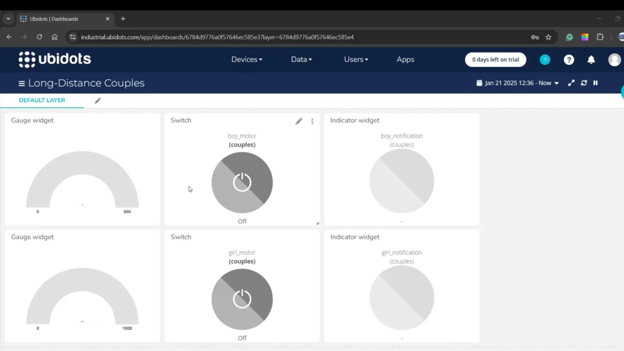
I made this dashboard for the Long-Distance Couples project, where I used two CrowPanel displays as smart bracelets. I used Ubidots as a bridge to connect the two smart bracelets.
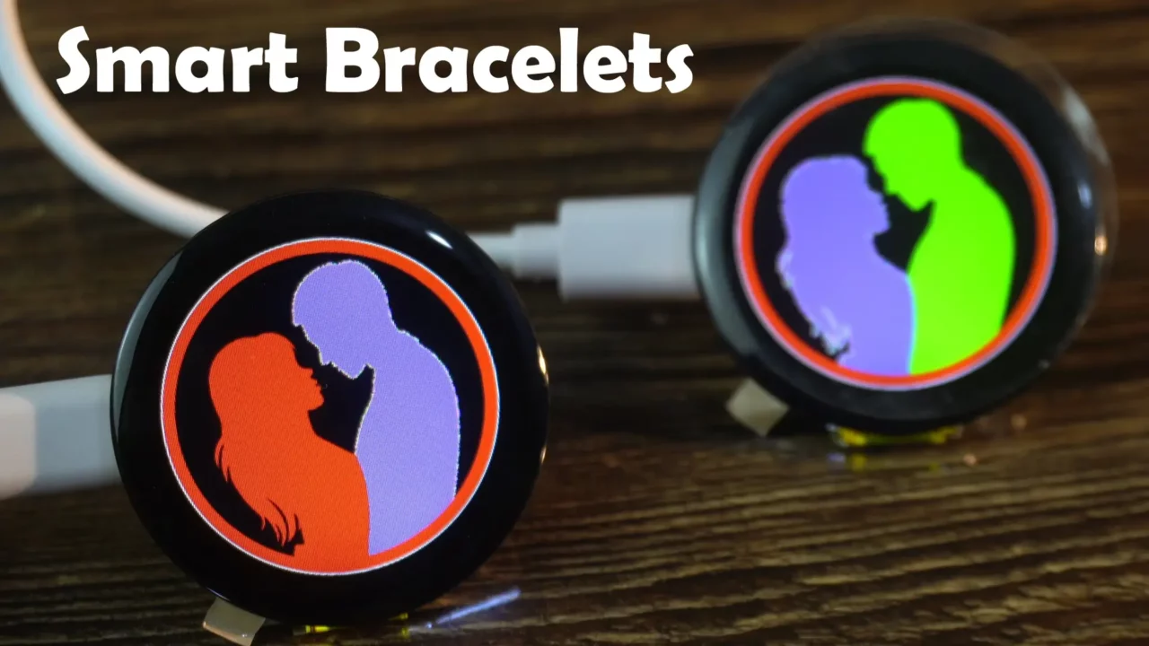
If you also want to amaze your girlfriend, you can make her this awesome smart bracelet.
Anyway, I’ve already explained most of the details in that article.
Simply, create a dashboard like this.
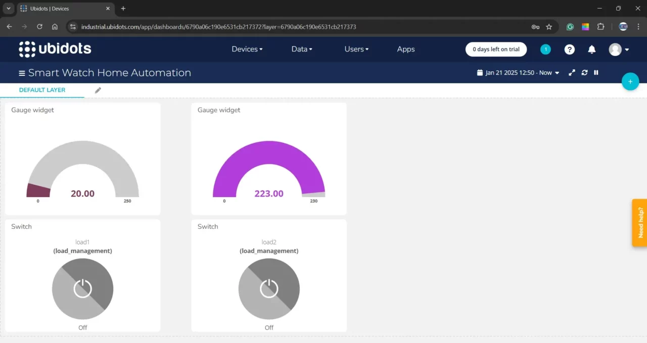
You can watch the video given at the end of this article. Anyway, copy the Token and paste it in the two codes given above. Finally, upload the programs.
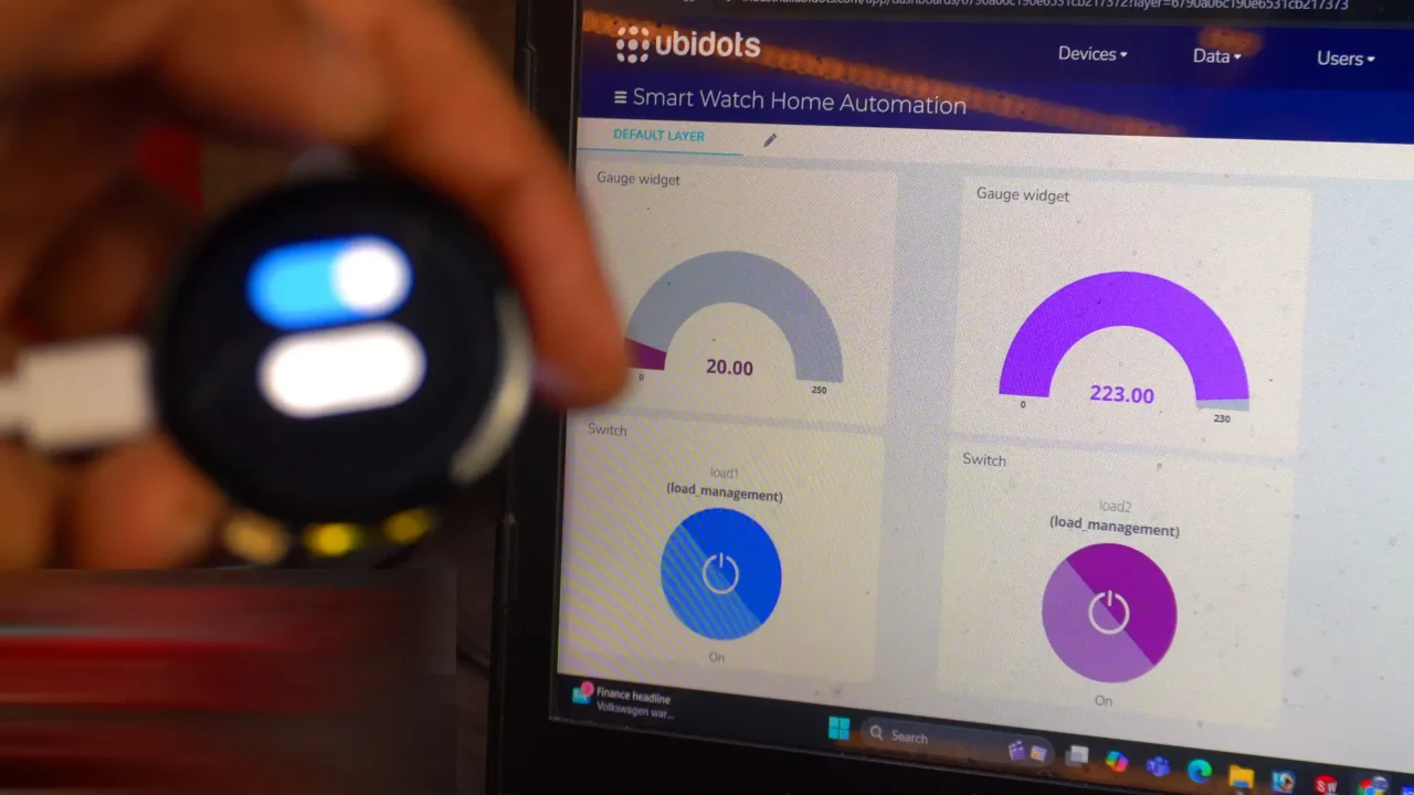
Not only we can control the loads and monitor the sensors through this dashboard, but we can also control the loads and monitor the sensors directly from the smartwatch.
Light control:

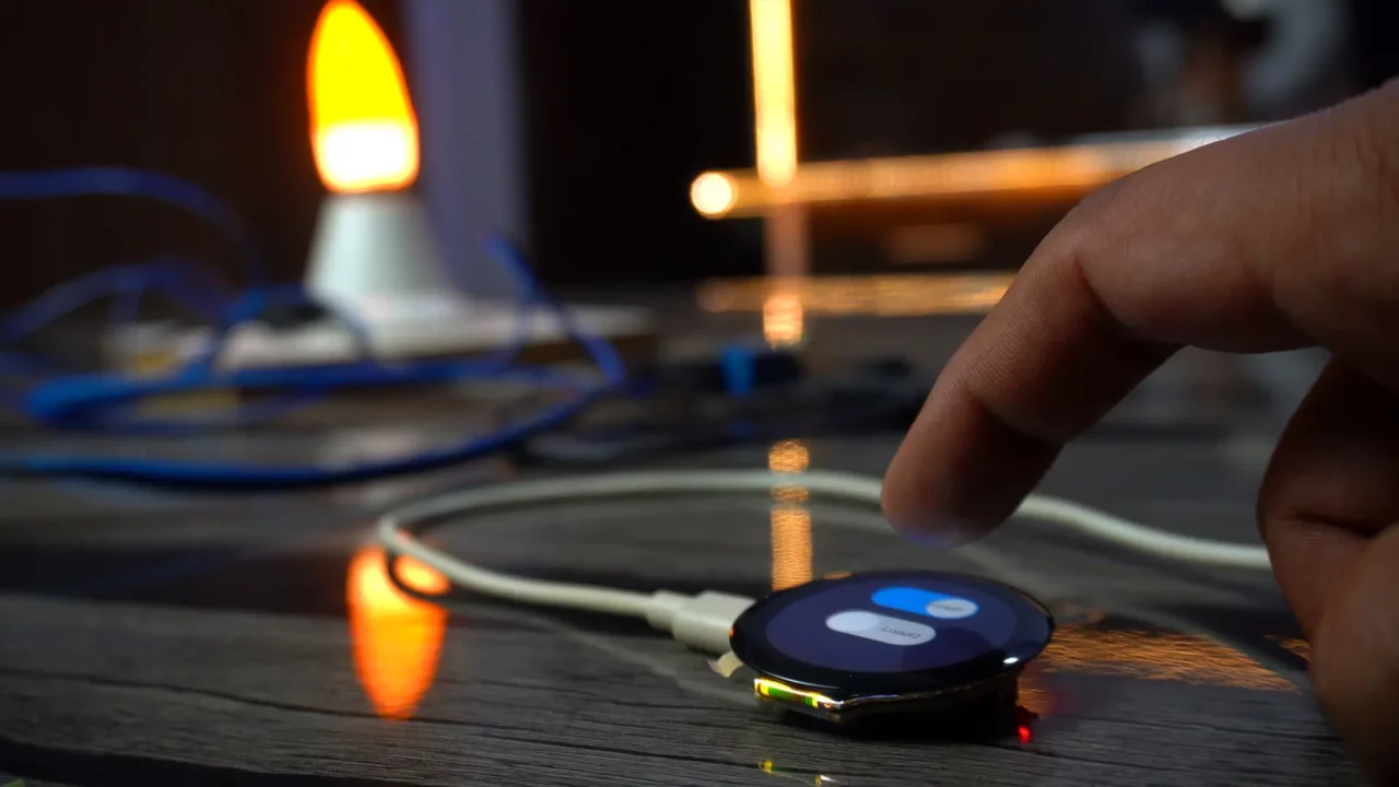
Smartwatch to control the Onboard LED.
Sensor Monitoring:

Watch Video Tutorial:

Discover more from Electronic Clinic
Subscribe to get the latest posts sent to your email.


