Vehicle Speed Detection or Vehicle Speed Measurement using IR Sensor and Arduino
Last Updated on August 17, 2024 by Engr. Shahzada Fahad
Table of Contents
Vehicle speed detection using IR sensor:
Vehicle Speed Detection or Vehicle Speed Measurement using IR Sensor and Arduino- In this tutorial, we will measure the speed of the vehicle using IR sensor, Arduino, and 16×2 LCD. In this project, we will use two IR sensors and place it at a certain distance. As we know that to measure the speed we need distance and time. In order to find time, we will use the logic that the first IR sensor will detect whether there is some vehicle is present in front of the sensor or not. Then the timer will start and will measure the duration up to the second IR sensor. The time we will get will be in milliseconds, so, in order to convert milliseconds into seconds, we will divide it by 1000. In this project, we have placed the two IR sensors at a distance of 20 centimeters which is equal to 0.2 meters. Now, we want our measured speed to be displayed in the kilometers per hour. So, in order to get the values in the kilometer per hour, we will use the following equation.
1m/s = Km/1000 x 3600/hr = 3.6Km/hr
1m/s = 3.6Km/hr
This logic will be used in our coding to measure the speed of the vehicle.
Amazon link:
Arduino Nano USB-C Type (Recommended)
*Disclosure: These are affiliate links. As an Amazon Associate I earn from qualifying purchases.
Working of IR sensor:
IR sensors are basically infrared sensors it consists of two main components one is the IR LED and the other is a photodiode. The IR LED is like a normal LED which will emit light but in the infrared spectrum. So therefore it is not visible to the naked eye and a photodiode which is also called a light-dependent resistor has a very high resistance in the absence of light and the resistance of the photodiode drops when light falls on it as the name itself indicate the resistance of the photodiode depends on the intensity of light falling on it. A photodiode is a semiconductor that has a PN Junction and it is operated in reverse bias. This is because it starts conducting the current in the reverse direction when light falls on it. I will explain about the IR LED photodiode and the working with the help of a circuit diagram.
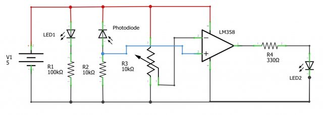
We have a +5 volt supply and a ground connection +5 volt is needed for the Op-Amp which is LM358, a photodiode, and an IR LED. So when it is powered on the IR LED emits light in the infrared spectrum and when it falls on the photodiode the resistance of the photodiode drops. We have used a 10 kilo-ohm resistor and a photodiode, the resistance of the photodiode varies so the voltage across this will be constant when there is no light. When light falls on it the resistance drops and therefore the voltage also changes and this is given to the non-inverting terminal of the op-amp and we have used a 10 kilo-ohm potentiometer and the output of the potentiometer is given to the non-inverting terminal of LM358 op-amp this potentiometer is just used as a reference. So let’s say if it is kept at 4 kilo-ohms voltage across this will be some value and the supply voltage is 5 volt. So 5 volt in combination with this 4 kilo-ohm resistance gives a certain amount of voltage which is fixed. It is given to pin 2 of the op-amp. So when light falls on this the resistance drops and when voltage varies though if the voltage goes below this voltage it the output will be low that is zero. If the voltage is more than this voltage the output will be high that is 1. So this will give us a digital output so it will be 1 or 0 and this IR and we have used the led which is just used as an indicator that indicates the output. If it is 1 the LED glows if it is 0 then it is off and a 330-ohm resistor is just used to protect the LED. We know LED is powered on with 3.3 voltage and here we have given +5 volts so therefore to protect the LED 330-ohm resistor is used. If you take a look at the IR sensor as you can see in the circuit diagram below, All the elements circuit elements are embedded in this tiny IR Sensor module which consists of IR leds, LM358 op-amp, and having three pins VCC, ground, and output and the potentiometer which can vary and this is photodiode IR LED resistors op-amp LM358 op-amp and we have 3 connection VCC ground and the output. So we can use IR sensors in different applications projects like line follower robots.
Vehicle speed detection Circuit diagram:

Now in the circuit diagram first we will connect the LCD with Arduino.
- Connect the VSS of the LCD with the Arduino ground
- Connect the VDD of the LCD with the 5V of the Arduino
- Connect the V0 with the Arduino ground
- Connect the RS of the LCD with the pin number 12 of the Arduino
- Connect the RN of the LCD with the ground
- Connect the E pin of the LCD with digital pin 11 of the Arduino
- Connect the D4 of the LCD with the digital pin 5 of the Arduino
- Connect the D5 of the LCD with the digital pin 4 of the Arduino
- Connect the D6 of the LCD with the digital pin 3 of the Arduino
- Connect the D7 of the LCD with the digital pin 2 of the Arduino
- Connect the A pin of the LCD with the 5V
- Connect the K pin of the LCD with the ground
Now to connect the IR sensor:
- Connect the VCC of both IR sensors with the 5V of the Arduino.
- Connect the ground of both IR sensors with the ground of the Arduino.
- Connect the output pin of the first IR sensor with digital pin 8 of the Arduino
- Connect the output pin of the second IR sensor with the digital pin 9 of the Arduino
Vehicle speed detection Code Explanation:
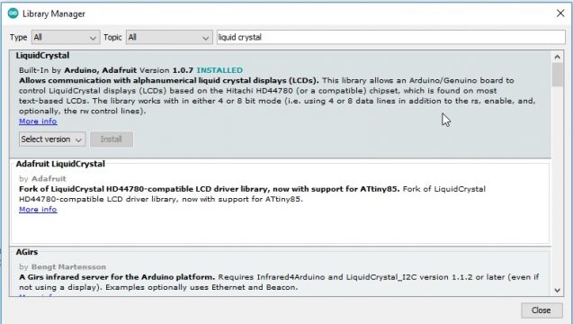
First of all, we will include a header file for the LCD. Go to the sketch and select include library in which click on the manage libraries and write liquid crystal and click on install.
|
1 |
<span style="font-size: 14pt; font-family: 'times new roman', times, serif;">#include <LiquidCrystal.h></span> |
Then we have defined the pins for the enable and data.
|
1 2 3 |
<span style="font-size: 14pt; font-family: 'times new roman', times, serif;">Const int rs = 12, en = 11, d4 = 5, d5 = 4, d6 = 3, d7 = 2; LiquidCrystallcd(rs, en, d4, d5, d6, d7);</span> |
This command shows that the IR sensors are connected to the pin numbers 8 and 9
|
1 2 3 |
<span style="font-size: 14pt; font-family: 'times new roman', times, serif;">int IR1 = 8; int IR2 = 9;</span> |
Then we have assigned two variables for measuring the time duration.
|
1 2 3 |
<span style="font-size: 14pt; font-family: 'times new roman', times, serif;">unsigned long t1 = 0; unsigned long t2 = 0;</span> |
then we have declared the velocity variable and using the formula we calculate the velocity.
|
1 2 3 4 5 6 7 |
<span style="font-size: 14pt; font-family: 'times new roman', times, serif;">float velocity; //int vkmh = (100*3600)/1000; void setup() {</span> |
This function will start the lcd
|
1 |
<span style="font-size: 14pt; font-family: 'times new roman', times, serif;">lcd.begin(16, 2);</span> |
Both the IR sensors will be used as input
|
1 2 3 4 5 6 7 8 9 10 11 12 13 14 15 16 17 18 19 20 21 22 23 24 25 26 27 28 29 30 31 32 33 34 35 36 37 38 39 40 41 42 43 44 45 46 47 48 49 50 51 52 |
<span style="font-size: 14pt; font-family: 'times new roman', times, serif;">pinMode(IR1, INPUT); pinMode(IR2, INPUT); Serial.begin(9600); lcd.clear(); lcd.begin(16, 2); lcd.setCursor(0, 0); lcd.print(" Vehicle Speed "); } void loop() { if (digitalRead(IR1) == 1) { t1 = millis(); } if (digitalRead(IR2) == 1) { t2 = millis(); } velocity = t2 - t1; velocity = velocity / 1000; //convert millisecond to second velocity = (0.2 / velocity) * 3.6; // km/s lcd.setCursor(2, 1); lcd.print(velocity); lcd.print(" Km/hr"); delay(500); }</span> |
Vehicle Speed Detection Complete code:
|
1 2 3 4 5 6 7 8 9 10 11 12 13 14 15 16 17 18 19 20 21 22 23 24 25 26 27 28 29 30 31 32 33 34 35 36 37 38 39 40 41 42 43 44 45 46 47 48 49 50 51 52 53 54 55 56 57 58 59 60 61 62 63 64 65 66 67 68 69 70 71 72 73 74 75 76 77 78 |
<span style="font-size: 14pt; font-family: 'times new roman', times, serif;">#include <LiquidCrystal.h> const int rs = 12, en = 11, d4 = 5, d5 = 4, d6 = 3, d7 = 2; LiquidCrystal lcd(rs, en, d4, d5, d6, d7); int IR1 = 8; int IR2 = 9; unsigned long t1 = 0; unsigned long t2 = 0; float velocity; //int vkmh = (100*3600)/1000; void setup() { lcd.begin(16, 2); pinMode(IR1, INPUT); pinMode(IR2, INPUT); Serial.begin(9600); lcd.clear(); lcd.begin(16, 2); lcd.setCursor(0, 0); lcd.print(" Vehicle Speed "); } void loop() { if (digitalRead(IR1) == 1) { t1 = millis(); } if (digitalRead(IR2) == 1) { t2 = millis(); } velocity = t2 - t1; velocity = velocity / 1000; //convert millisecond to second velocity = (0.2 / velocity) * 3.6; // km/s lcd.setCursor(2, 1); lcd.print(velocity); lcd.print(" Km/hr"); delay(500); }</span> |
After uploading the code to the Arduino, when we will move the object or something else in front of the IR sensors the speed will be displayed on the LCD. The IR sensors offer a low detection range, to solve this issue, you can use Ultrasonic Sensors, and then you can make a complete product that you can test with real cars and vehicles. I hope this basic tutorial helps you in making your project. You can also join my YouTube channel “Electronic Clinic”.
Discover more from Electronic Clinic
Subscribe to get the latest posts sent to your email.


