Arduino IR Sensor & Buzzer Circuit diagram and Programming
Last Updated on August 16, 2024 by Engr. Shahzada Fahad
Table of Contents
Arduino IR Sensor & Buzzer, Example:
Arduino IR Sensor & Buzzer Circuit Diagram and Programming- In this example, I am going to explain how to use an IR sensor and Buzzer with the Arduino. You will need an IR sensor like this for obstacle detection, for making security systems, for making line following robots, and even for making contactless control systems like for example a doorbell etc.
Amazon Links:
Arduino Nano USB-C Type (Recommended)
*Disclosure: These are affiliate links. As an Amazon Associate I earn from qualifying purchases.
In this example, what I want to do is, I want the buzzer to turn ON when the IR sensor detects any object. Instead of controlling a buzzer, you can also control a relay to control high voltage AC and DC loads.
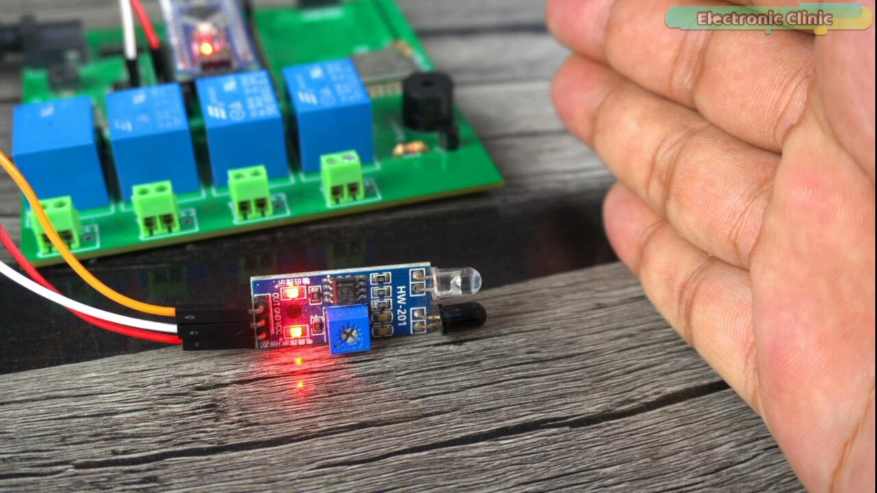
Anyway, this IR sensor has these two Infrared Leds, this white LED is used as the transmitter and this Black color LED is used as the receiver. It transmits the infrared light which reflects from an object and when the receiver LED detects the reflected light, it knows there is something in front of the sensor, and then it signals the Arduino.
This IR Sensor also has a Blue color Potentiometer which is used to set the range. It offers a long range when used against white color and reflective objects and it offer shorter range when used against black objects. That’s why the IR sensors are most frequently used in line follower robots. And you might have seen the black lines are usually drawn on a white paper or a surface that’s more reflective than the Black color.
This IR sensor has a total of three wires which are clearly labeled with VCC, GND, and OUT.
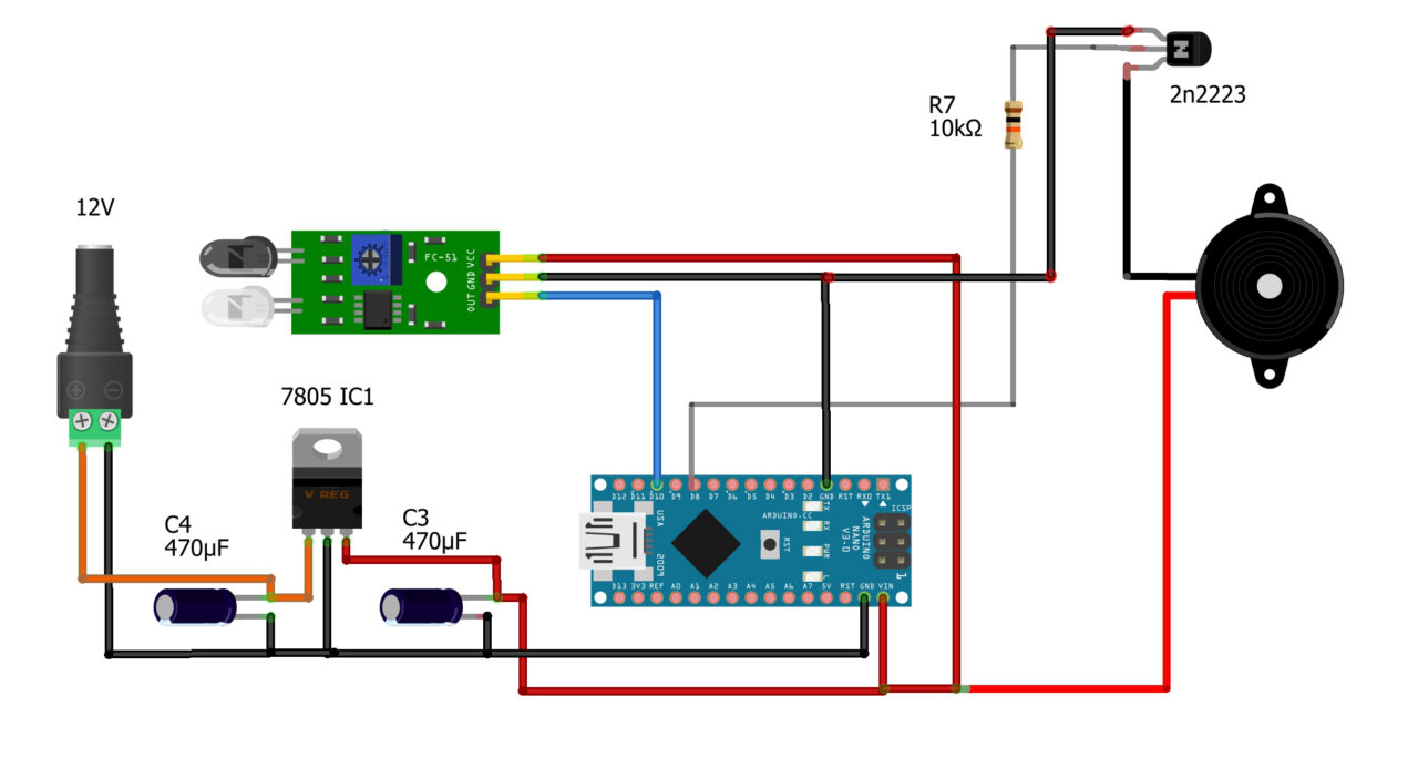
Connect the VCC and GND pins to the Arduino 5V and GND. Connect the Out pin to the Arduino Pin D10.
The buzzer is connected to the Arduino Pin D8 through a driver circuit consisting of 2n2222 NPN transistor and a 10Km resistor. And now let’s go ahead and take a look at the programming.
Arduino IR Sensor Programming:
|
1 2 3 4 5 6 7 8 9 10 11 12 13 14 15 16 17 18 19 20 21 22 23 24 25 26 |
int buzzer = 8; // 5V buzzer is connected to the Arduino pin D8 int irpin = 10; // The 5V IR Obstacle sensor is connected to the Arduino pin D10 int irstatus = HIGH; // stores the status of the IR Sensor in the form of 1 and 0 void setup() { Serial.begin(9600); // Activates Serial communication pinMode(buzzer, OUTPUT); // Buzzer is output device pinMode(irpin, INPUT); // Ir Sensor is an Input Device } void loop() { irstatus = digitalRead(irpin); // Reads a digital signal 5V or Gnd on the Arduino pin D10 if (irstatus == LOW) { // The type of IR Sensor i am using outputs 0 when it detects an object digitalWrite(buzzer, HIGH); // Turn on the Buzzer delay(2000); // two seconds delay digitalWrite(buzzer, LOW); // turns OFF the buzzer } else { // if there is nothing in front of the IR sensor digitalWrite(buzzer, LOW); // keep the buzzer off. } delay(200); } |
I already explained in my previous example and I am sure now you can read this program and I am sure now you fully understand how to define variables and how to use these built-in functions.
Anyway, this program is quite similar to the digital input example in which I used a push button for reading the button clicks. And in that example I clearly explained about different sensors that gave 0 or 1 at the output. In that example I used the built-in pullup resistor. But this time I didn’t enable the pullup resistor because the IR sensor I am using pulls it to 5 volts.
When the sensor detects anything it gives 0 at the output and when there is nothing in front of the sensor then it gives 5 volts at the output. So, when the sensor gives you two states then there is no need to activate the pullup resistor. Rest of the program is almost the same. We simply read the pin status and then accordingly control the buzzer. I have commented all the instructions.
For the step by step explanation and practical demonstration watch the video tutorial given at the end of this article.
video tutorial
Discover more from Electronic Clinic
Subscribe to get the latest posts sent to your email.


