Arduino LDR Sensor: Day and Night detection system Circuit Diagram and Programming
Last Updated on August 16, 2024 by Engr. Shahzada Fahad
Table of Contents
Arduino LDR Sensor, Example:
In this example, we are going to cover two things an LDR Sensor and a 5V SPDT type relay. In the previous example, we controlled a 5V buzzer and this time a 5V relay so, that you can get the idea of how to control high voltage loads. In this example, we are going to control a 110/220Vac light bulb. It’s basically a day and night-detection system. The bulb turns ON and OFF depending on the light intensity. If the light falls below a certain threshold limit the bulb turns ON and vice versa.
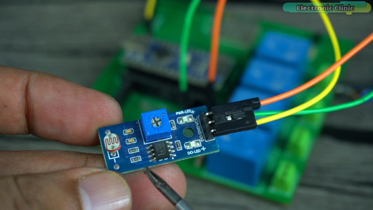
You know an LDR sensor is basically an analog sensor but this board is designed in a way that it gives 0 or 1 at the output when the light increases above or decreases below a set limit. So, this is a digital LDR sensor. And you can see this sensor board has a potentiometer which you can use to set the light sensitivity.
This sensor has a total of 3 pins which are clearly labeled with D0, GND, and VCC.
Amazon Links:
Arduino Nano USB-C Type (Recommended)
*Disclosure: These are affiliate links. As an Amazon Associate I earn from qualifying purchases.
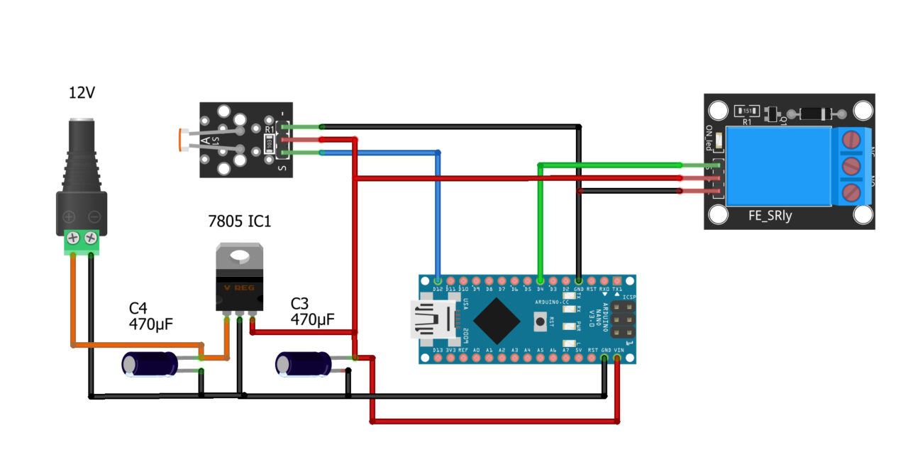
Connect D0 pin to the Arduino digital pin D12. Connect the VCC and GND pins to the Arduino 5V and GND pins.
A 5V SPDT type relay is connected to the Arduino pin D4. Now let’s go ahead and take a look at the programming.
Arduino LDR Sensor Programming:
|
1 2 3 4 5 6 7 8 9 10 11 12 13 14 15 16 17 18 19 20 21 22 23 24 25 |
int Sensor = 12; // Ldr Senosr int relay = 4; // 5v Relay Module void setup() { //Serial.begin(9600); pinMode (Sensor, INPUT); // LDR is an input device pinMode (relay, OUTPUT); // relay is an output device } void loop() { if(digitalRead(Sensor) == HIGH) // reads the digital signal, if light is not falling { digitalWrite(relay, HIGH); // turns on the light delay(3000); } if(digitalRead(Sensor) == LOW) // if light is falling on the LDR sensor { digitalWrite(relay, LOW); // turn off the light } } |
This program is just like the IR Digital Sensor program. Almost all the basic digital sensors work in the same exact way. We simply define the pins and then tell the controller which pins are going to be used as the input and which pins are going to be used as the output. Then we use the digitalRead() function to read the pin and then accordingly control the output. Instead of controlling the relay, we can add code for the GSM module to send a text message. Or you can turn on a Siren if incase you want to make a security system, or you can turn ON and turn OFF a DC or AC motor. It totally depends on you; how you decide to use it. Anyway, I have already uploaded this program and now let’s watch the Day and night Detection system in Action.

The 110/220Vac bulb is connected to the Relay and you can see the Arduino is powered up. When the 110/220Vac supply is connected never touch the relay contacts or copper traces on the top and bottom side of the PCB as it can be really dangerous. So, as far as possible wear protective gloves and as a beginner I would recommend to perform such high voltage experiments in front of someone having basic knowledge of the electricity rules and regulations. So, remember safety comes first.
For the demonstration purposes I am going to use my studio’s soft light as the sun. So, when the soft light is ON the bulb will remain OFF and when the soft light is turned off then the 110/220Vac bulb is going to turn ON.
As you can see the image above, the soft light is off that’s why the 110/220Vac bulb is ON.
If you replace this LDR sensor with a PIR motion sensor you can build yourself an automatic Corridor light controller or lawn light controller, or an automatic staircase light controller.
For the step by step explanation and practical demonstration watch the video tutorial given at the end of this article.
video tutorial

Discover more from Electronic Clinic
Subscribe to get the latest posts sent to your email.


