Arduino LoRa GPS Tracker for Car, GPS Lora Tracker, Geofence tracker, GPS Vehicle Tracking
Last Updated on September 21, 2024 by Engr. Shahzada Fahad
Table of Contents
Arduino LoRa GPS Tracker for a Car:
Arduino LoRa GPS Tracker for Car- In this article, you will learn how to make a Car/Vehicle tracking system using Arduino, Neo 6M GPS module, a pair of SX1278 LoRa transceiver modules, a 1-channel relay module, SSD1306 Oled display module, and a 5V buzzer.
Besides the car GPS coordinates, this LoRa GPS tracker also informs you whether the car is within the Geofence region or is it outside the Geofence. So, you may also call this GPS LoRa tracker a Geofence tracker. Further, this Arduino-based LoRa tracker also displays the distance and by using this button, you can also disable a car’s computer system, and then nobody can start your car. A lot of things are going to be explained within this article. So, relax and keep reading this article. And, if you have any sort of query in your mind, you can ask about it in the comments section or if you have any suggestions, you are most welcome.
Anyhow, before a practical demonstration, there are certain points, which are very important and which I want to share with you. In my last two projects, I designed two different types of trackers.
In my first project, I implemented Geofencing technology in an attempt to reinforce my car security.
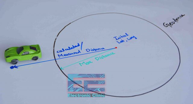
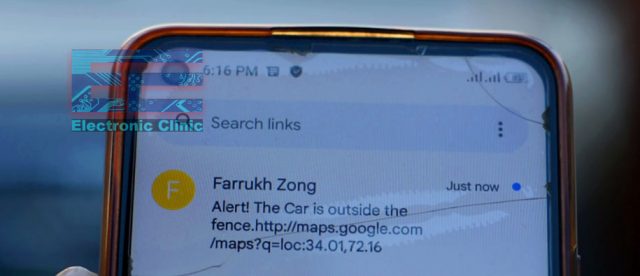
As I have elaborated in my previous article, you can define a virtual boundary around any area with the help of Geofencing by means of using GPS coordinates. In a similar fashion, I built up a virtual fence for my car so that whenever my car happened to go out of that prescribed area, I received an alert message on my cell phone which prompted me that “the car is outside the fence”.
The vehicle tracking system, which I designed in my 2nd project, was quite amazing. You can request your car’s GPS coordinates at any time by sending a message from your cell phone.
The best thing about my designed tracker is that it also sends you a Google map link apart from the GPS coordinates. By using this link, you can find your car or any other vehicle by tracking it. To clearly explain the GSM-based car tracking system, I used my car to be stolen and then I located it with the help of the tracker.
![]()
Moreover, I also introduced the accident monitoring feature in my car tracker. Whenever the car’s front bumper was hit, I received an accident alert message on my cell phone. Furthermore, I also added the function of over-speed monitoring in my car’s tracker. Whenever a car’s speed exceeded a certain limit, the buzzer always turned ON and it kept turning ON as long the car speed was not reduced.
Guys, you might think that when I have already done all this on such an advanced level, then what is the need for making a LoRa GPS tracker? The answer is pretty simple. I used GSM in those two trackers, and in today’s car tracker, I am going to use LoRa.
Now it is up to you to decide whether you have to use a GSM or LoRa for your car’s tracking. If you want to track your car within a range of thousands of kilometers, then I suggest you use GSM. However, it is worth remembering here that thieves have GSM jammers nowadays, and when they plan to steal your car, you will not receive any message on your cell phone. This is one of the greatest drawbacks of the GSM-based tracking system.
And, if you use the long-range LoRa tracker, you can track your car within a range of up to 10 km in real-time. And, if you use LoRaWAN, then you can even track your car within thousands of km range.
As you know LoRa GPS is an absolutely new technology, so thieves do not have jammers for it as yet, which is obviously a plus point.
My designed LoRa GPS tracker is pretty tension free because I have applied Geofencing technology to it. So, as soon as the car drives out from the Geofence, the buzzer will turn ON, and then I can wirelessly disable the management system of my car by pressing this button. For practical demonstration watch the video tutorial given at the end of this Article.
Practical demonstration:
![]()
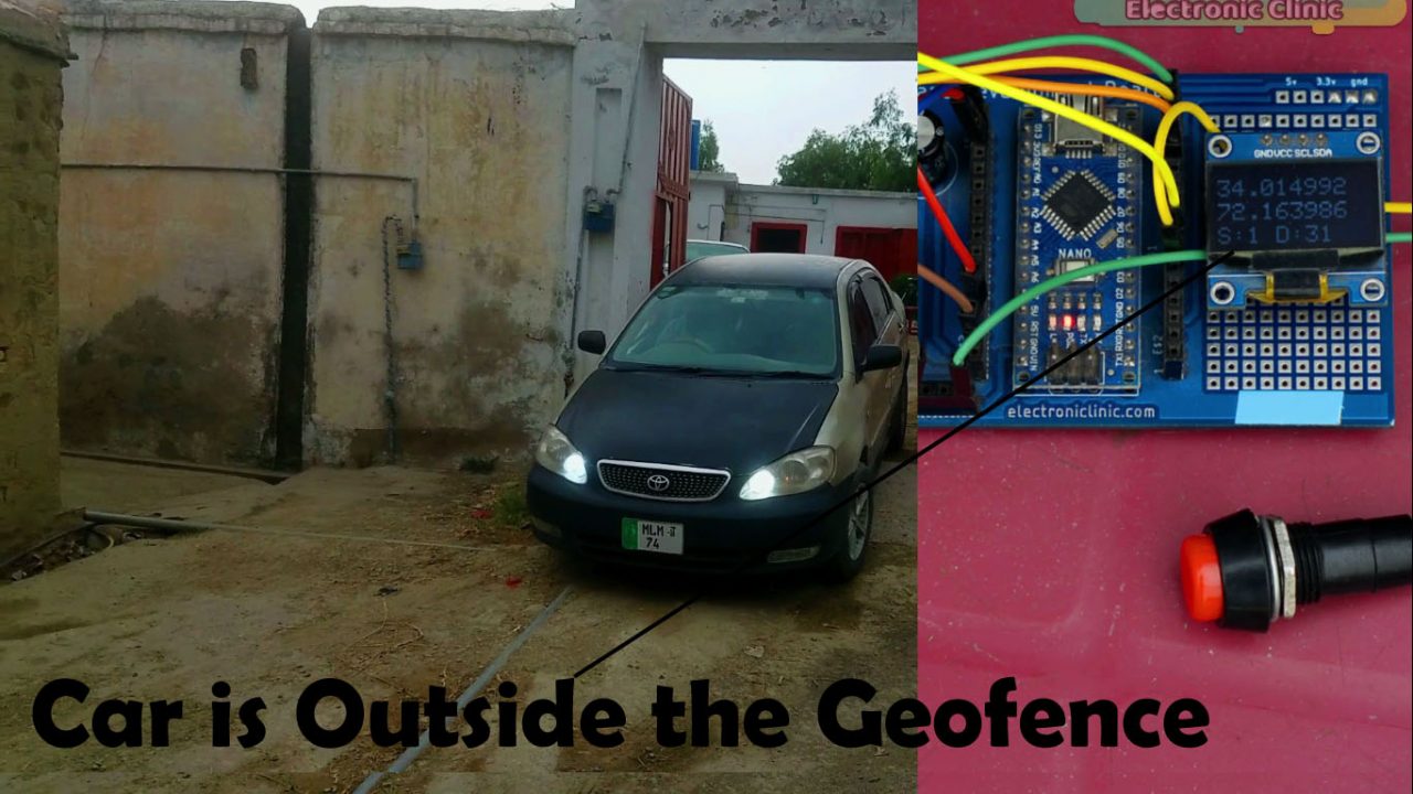
This place is the center point of my Geofence and the maximum distance which I have selected is 30 meters. I have already explained the Geofencing technology and its implementation in detail.
![]()
For demonstration purposes, I have connected a relay with the front lights of my car. While in its real implementation, you have to make this connection with the wire, through which the car’s entire computer system can be turned ON or OFF. For this purpose, you can view the wiring diagram of your car, otherwise, you may contact an experienced car technician.
Anyway, now I can control the front lights of my Car using button on the receiver side.
![]()
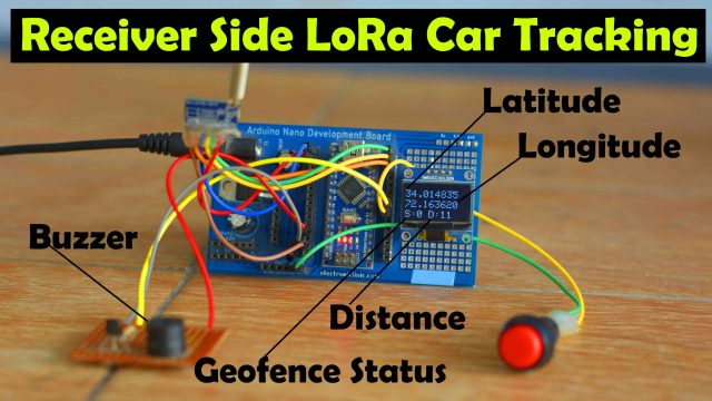
Right now, the lights are ON, which means that the car’s computer system is ON and my brother can start the car. Now as soon as my brother drives out the car from the Geofence, the buzzer on the receiver’s side will turn ON, which will indicate that the car has gone out from the Geofence, and then I can disable the car’s computer system by pressing this button. Now you can view the car’s real location on the display. As the car is still within the limits of the Geofence, therefore 0 is written on the display. When the car gets out from the Geofence, then 1 will be displayed here.
There is a distance on its side, which is actually the distance between the car and the Geofence center. It means that this distance shows how much the car is away from the center of the Geofence.
On the display you can see the D:31 this means the distance has exceeded the maximum limit which is 30 meters, this means the car has moved outside the Geofence and this is why you can see 1 next to S. When the receiver gets S:1 the buzzer is turned ON.
Now by pressing this button, I can turn OFF the Car’s computer system, which I am presenting through lights.
So, you have watched practically, how useful this system is. Not only a car, but you can track down any object through this system. You can track your animals, to be more specific, you can use it as a dog tracker, and so on. I am sure by now you might have got an idea of how does this system works. So, without any further delay, let’s get started!!!
Amazon Links:
Arduino Nano USB-C Type (Recommended)
SSD1306 128×64 Oled i2c display Module
*Disclosure: These are affiliate links. As an Amazon Associate I earn from qualifying purchases.
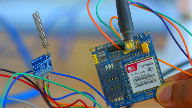
SX1278 LoRa Module:
In this project we are using the same SX-1278 LoRa modules for the transmitter and receiver. In order to use it as a receiver and transmitter we will make change in the code. Lora SX-1278 long distance wireless transceiver module integrates Semtech RF transceiver chip SX1278, which adopts LoRa TM Spread Spectrum modulation frequency hopping technique. The features of long distance and high sensitivity (-139dBm) make this module perform better than FSK and GFSK module. Multi-signal won’t affect each other even in crowd frequency environment; it comes with strong anti-interference performance. This module is 100mW and ultra small size, widely used in AMR , remote industrial control filed.
![]()
Features:
- Frequency Range: 868 / 915 MHz
- Sensitivity up to -139dBm @Lora
- Maximum output power: 20 dBm
- 13mA@receiver mode
- Sleep current <200 nA
- Data transfer rate: @FSK,1.2-300 Kbps
- @Lora TM, 0.018-37.5 Kbps
- Lora TM, FSK, GFSK & OOK Modulation mode
- Built-in ESD Protection
- 127 dB Dynamic Range RSSI
- Packet engine up to 256 bytes with FIFO and CRC
- Hopping frequency
- Built-in temperature sensor and low battery indicator
- Excellent blocking immunity
- Operating Temperature Range:-40 ~ + 85 °C
Applications:
- Remote control
- Remote meter reading
- Home security alarm and remote keyless entry
- Industrial control
- Home automation remote sensing
- Individual data records
- Toys control
- Sensor network
- Tire pressure monitoring
- Health monitoring
- Wireless PC peripherals
- Tag reading and writing
Neo 6M GPS Module:
![]()
GPS or Global Positioning System is a satellite navigation system that furnishes location and time information in all climate conditions to the user. GPS is used for navigation in planes, ships, cars, and so on. GPS provides continuous real-time, 3-dimensional positioning, navigation, and timing worldwide. The GPS is used to finding the Longitude and Latitude values.
Features:
- Power supply: 3V-5V
- Models: GY – GPS6MV2
- Module with ceramic antenna, signal strong
- EEPROM save the configuration parameter data when power down
- With data backup battery
- The LED signal lights
- The default baud rate: 9600
- Compatible with various flight control modules
- Module size 25 x 35 mm (0.98” x 1.37”)
- Antenna size: 25 x 25 mm (0.98”x 0.98”)
LoRa GPS Tracker Tx, Circuit Diagram:
![]()
The Tx and Rx pins of the Neo 6M GPS module are connected with the Arduino pins 8 and 9, while the VCC and GND pins of the GPS module are connected with the Arduino’s 5V and GND.
One channel relay module is connected with the Arduino digital pin 3. While the voltage and ground pins of the relay module are connected with the 12 volts, and GND.
The VCC of the LoRa module is connected with the 3.3V of the Arduino. The MISO Pin of the LoRa module is connected with the Arduino pin 12. The MOSI pin is connected with pin 11. The SCK pin of the LoRa module is connected with pin 13. The NSS pin is connected with the Arduino’s pin 10 and the ground pin of the LoRa module is connected with the Arduino’s GND.
On the left side, you can see a 5V regulated power supply based on the LM7805 voltage regulator. We use this regulated 5 volts to power up the Arduino and all the other electronics.
LoRa GPS Tracker Rx, Circuit Diagram:
![]()
The connections of the 5V regulated power supply and SX1278 Lora Transceiver module remain exactly the same.
The SDA and SCL or SCK pins of the SSD1306 Oled display module are connected with the A4 and A5 pins of the Arduino. While the VCC and GND pins of the Oled display module are connected with the Arduino’s 5 volts and GND pins.
A Button is connected with Digital pin D4. A 5V buzzer is connected with the Arduino Pin 5. A 2n2222 NPN transistor is used to control the 5V buzzer. Now, let’s take a look at the programming.
LoRa GPS Tracker Programming:
This Arduino and LoRa-based Car GPS tracking system is based on two programs. One program is written for the transmitter side to which GPS is connected, whereas another program is written for the receiver side. Download the following libraries.
LoRa GPS Tracker, Arduino Tx Code:
|
1 2 3 4 5 6 7 8 9 10 11 12 13 14 15 16 17 18 19 20 21 22 23 24 25 26 27 28 29 30 31 32 33 34 35 36 37 38 39 40 41 42 43 44 45 46 47 48 49 50 51 52 53 54 55 56 57 58 59 60 61 62 63 64 65 66 67 68 69 70 71 72 73 74 75 76 77 78 79 80 81 82 83 84 85 86 87 88 89 90 91 92 93 94 95 96 97 98 99 100 101 102 103 104 105 106 107 108 109 110 111 112 113 114 115 116 117 118 119 120 121 122 123 124 125 126 127 128 129 130 131 132 133 134 135 136 137 138 139 140 141 142 143 144 145 146 147 148 149 150 151 152 153 154 155 156 157 158 159 160 161 162 163 164 165 166 167 168 169 170 171 172 173 174 175 176 177 178 179 180 181 182 183 184 185 186 187 188 189 190 191 192 193 194 195 196 197 198 199 200 201 202 203 204 205 206 207 208 209 210 211 212 213 214 215 216 217 218 219 220 221 222 223 224 225 226 227 228 229 230 231 232 233 234 235 236 237 238 239 240 241 242 243 244 245 246 247 248 249 250 251 252 253 254 255 256 257 258 259 260 261 262 263 264 265 266 267 268 269 270 271 272 273 274 275 276 277 278 279 280 281 282 283 284 285 286 287 288 289 290 291 292 293 294 295 296 297 298 299 300 301 |
// Transmitter #include <SoftwareSerial.h> #include <AltSoftSerial.h> #include <TinyGPS++.h> #include <SPI.h> // include libraries #include <LoRa.h> //-------------------------------------------------------------- #include <Adafruit_GFX.h> #include <Adafruit_SSD1306.h> //------------------------------- static const int RXPin = 8, TXPin = 9; static const uint32_t GPSBaud = 9600; // The TinyGPS++ object TinyGPSPlus gps; // The serial connection to the GPS device SoftwareSerial ss(RXPin, TXPin); // for gps ///////////////////////////////////////////////////// String outgoing; // outgoing message byte msgCount = 0; // count of outgoing messages byte destination = 0xFF; byte localAddress = 0xBB; long lastSendTime = 0; // last send time int interval = 2000; // interval between sends ///---------------------- // For Oled display #define SCREEN_WIDTH 128 // OLED display width, in pixels #define SCREEN_HEIGHT 64 // OLED display height, in pixels // Declaration for an SSD1306 display connected to I2C (SDA, SCL pins) #define OLED_RESET -1 // Reset pin # (or -1 if sharing Arduino reset pin) Adafruit_SSD1306 display(SCREEN_WIDTH, SCREEN_HEIGHT, &Wire, OLED_RESET); ///------------------------------- String Mymessage = ""; //-------------------------------------------------------------- // Size of the geo fence (in meters) const float maxDistance = 30; //-------------------------------------------------------------- float initialLatitude = 34.014875; float initialLongitude = 72.163585; float latitude, longitude; char buff[10]; String mylong = ""; // for storing the longittude value String mylati = ""; // for storing the latitude value //-------------------------------------------------------------- int msgstatus; int Sensor1; int relay = 3; float distance; /***************************************************************************************** * setup() function *****************************************************************************************/ void setup() { //-------------------------------------------------------------- //Serial.println("Arduino serial initialize"); Serial.begin(9600); display.begin(SSD1306_SWITCHCAPVCC, 0x3C); display.clearDisplay(); display.setTextColor(WHITE); pinMode(relay, OUTPUT); //-------------------------------------------------------------- //Serial.println("NEO6M serial initialize"); ss.begin(GPSBaud); //-------------------------------------------------------------- if (!LoRa.begin(433E6)) { Serial.println("LoRa init failed. Check your connections."); while (true); // if failed, do nothing } Serial.println("LoRa init succeeded."); } /***************************************************************************************** * loop() function *****************************************************************************************/ void loop() { while (ss.available() > 0) if ( gps.encode(ss.read() ) ) { displayInfo(); latitude = gps.location.lat(), 6 ; longitude = gps.location.lng(), 6 ; mylati = dtostrf(latitude, 3, 6, buff); mylong = dtostrf(longitude, 3, 6, buff); distance = getDistance(latitude, longitude, initialLatitude, initialLongitude); } //-------------------------------------------------------------- if (millis() - lastSendTime > interval) { //displayInfo(); // Serial.print("Latitude= "); Serial.println(latitude, 6); //Serial.print("Lngitude= "); Serial.println(longitude, 6); if(distance > maxDistance) { msgstatus =1; } if(distance < maxDistance) { msgstatus =0; } // Serial.print("Distance: "); //Serial.println(distance); Mymessage = Mymessage + mylati +"," + mylong+","+msgstatus + "," +distance ; sendMessage(Mymessage); //Serial.println(Mymessage); delay(50); Mymessage = ""; //Serial.println("Sending " + message); lastSendTime = millis(); // timestamp the message } // parse for a packet, and call onReceive with the result: onReceive(LoRa.parsePacket()); } // Calculate distance between two points float getDistance(float flat1, float flon1, float flat2, float flon2) { // Variables float dist_calc=0; float dist_calc2=0; float diflat=0; float diflon=0; // Calculations diflat = radians(flat2-flat1); flat1 = radians(flat1); flat2 = radians(flat2); diflon = radians((flon2)-(flon1)); dist_calc = (sin(diflat/2.0)*sin(diflat/2.0)); dist_calc2 = cos(flat1); dist_calc2*=cos(flat2); dist_calc2*=sin(diflon/2.0); dist_calc2*=sin(diflon/2.0); dist_calc +=dist_calc2; dist_calc=(2*atan2(sqrt(dist_calc),sqrt(1.0-dist_calc))); dist_calc*=6371000.0; //Converting to meters return dist_calc; } void sendMessage(String outgoing) { LoRa.beginPacket(); // start packet LoRa.write(destination); // add destination address LoRa.write(localAddress); // add sender address LoRa.write(msgCount); // add message ID LoRa.write(outgoing.length()); // add payload length LoRa.print(outgoing); // add payload LoRa.endPacket(); // finish packet and send it msgCount++; // increment message ID } void onReceive(int packetSize) { if (packetSize == 0) return; // if there's no packet, return // read packet header bytes: int recipient = LoRa.read(); // recipient address byte sender = LoRa.read(); // sender address byte incomingMsgId = LoRa.read(); // incoming msg ID byte incomingLength = LoRa.read(); // incoming msg length String incoming = ""; while (LoRa.available()) { incoming += (char)LoRa.read(); } if (incomingLength != incoming.length()) { // check length for error //Serial.println("error: message length does not match length"); ; return; // skip rest of function } // if the recipient isn't this device or broadcast, if (recipient != localAddress && recipient != 0xFF) { // Serial.println("This message is not for me."); ; return; // skip rest of function } // if message is for this device, or broadcast, print details: //Serial.println("Received from: 0x" + String(sender, HEX)); //Serial.println("Sent to: 0x" + String(recipient, HEX)); //Serial.println("Message ID: " + String(incomingMsgId)); // Serial.println("Message length: " + String(incomingLength)); // Serial.println("Message: " + incoming); // Serial.println("RSSI: " + String(LoRa.packetRssi())); // Serial.println("Snr: " + String(LoRa.packetSnr())); // Serial.println(); String q = getValue(incoming, ',', 0); // Latitude Serial.println(q); Sensor1 = q.toInt(); // latitude if ( Sensor1 == 1 ) { digitalWrite(relay, HIGH); } if ( Sensor1 == 0 ) { digitalWrite(relay, LOW); } } void displayInfo() { Serial.print(F("Location: ")); if (gps.location.isValid()) { Serial.print(gps.location.lat(), 6); Serial.print(F(",")); Serial.print(gps.location.lng(), 6); Serial.print(" "); Serial.print(F("Speed:")); Serial.print(gps.speed.kmph()); } else { Serial.print(F("INVALID")); } Serial.print(F(" Date/Time: ")); if (gps.date.isValid()) { Serial.print(gps.date.month()); Serial.print(F("/")); Serial.print(gps.date.day()); Serial.print(F("/")); Serial.print(gps.date.year()); } else { Serial.print(F("INVALID")); } Serial.print(F(" ")); if (gps.time.isValid()) { if (gps.time.hour() < 10) Serial.print(F("0")); Serial.print(gps.time.hour()); Serial.print(F(":")); if (gps.time.minute() < 10) Serial.print(F("0")); Serial.print(gps.time.minute()); Serial.print(F(":")); if (gps.time.second() < 10) Serial.print(F("0")); Serial.print(gps.time.second()); Serial.print(F(".")); if (gps.time.centisecond() < 10) Serial.print(F("0")); Serial.print(gps.time.centisecond()); } else { Serial.print(F("INVALID")); } Serial.println(); } String getValue(String data, char separator, int index) { int found = 0; int strIndex[] = { 0, -1 }; int maxIndex = data.length() - 1; for (int i = 0; i <= maxIndex && found <= index; i++) { if (data.charAt(i) == separator || i == maxIndex) { found++; strIndex[0] = strIndex[1] + 1; strIndex[1] = (i == maxIndex) ? i+1 : i; } } return found > index ? data.substring(strIndex[0], strIndex[1]) : ""; } |
I created this code by combining the codes of my previous two projects. LoRa based two way communication system and Arduino Geofencing technology. So, the purpose of this code is to find the distance between any two GPS co-ordinates using the Haversine formula and then accordingly set the status.
|
1 2 3 |
Mymessage = Mymessage + mylati +"," + mylong+","+msgstatus + "," +distance ; sendMessage(Mymessage); |
Finally, I send the complete message which consists of the Latitude, Longitude, Status, and distance values.
It also controls the relay depending on the signal received from the receiver side. So, the transmitter side is able to send and receive the data. Now, let’s take a look at the Receiver side programming.
LoRa GPS Tracker, Arduino Rx Code:
|
1 2 3 4 5 6 7 8 9 10 11 12 13 14 15 16 17 18 19 20 21 22 23 24 25 26 27 28 29 30 31 32 33 34 35 36 37 38 39 40 41 42 43 44 45 46 47 48 49 50 51 52 53 54 55 56 57 58 59 60 61 62 63 64 65 66 67 68 69 70 71 72 73 74 75 76 77 78 79 80 81 82 83 84 85 86 87 88 89 90 91 92 93 94 95 96 97 98 99 100 101 102 103 104 105 106 107 108 109 110 111 112 113 114 115 116 117 118 119 120 121 122 123 124 125 126 127 128 129 130 131 132 133 134 135 136 137 138 139 140 141 142 143 144 145 146 147 148 149 150 151 152 153 154 155 156 157 158 159 160 161 162 163 164 165 166 167 168 169 170 171 172 173 174 175 176 177 178 179 180 181 182 183 184 185 186 187 188 189 190 191 192 193 194 195 196 197 198 199 |
/* //Receiver */ #include <SPI.h> // include libraries #include <LoRa.h> #include <Adafruit_GFX.h> #include <Adafruit_SSD1306.h> #define SCREEN_WIDTH 128 // OLED display width, in pixels #define SCREEN_HEIGHT 64 // OLED display height, in pixels // Declaration for an SSD1306 display connected to I2C (SDA, SCL pins) #define OLED_RESET -1 // Reset pin # (or -1 if sharing Arduino reset pin) Adafruit_SSD1306 display(SCREEN_WIDTH, SCREEN_HEIGHT, &Wire, OLED_RESET); int Buzzer=5; int button=4; int buttonState; int Distance; boolean Bflag = false; String SenderNode = ""; String outgoing; // outgoing message byte msgCount = 0; // count of outgoing messages byte localAddress = 0xFF; // address of this device byte destination = 0xBB; // destination to send to long lastSendTime = 0; // last send time int interval = 2000; // interval between sends String incoming = ""; String statusmessage = ""; int Sensor1 = 0; // Latitude int Sensor2 = 0; // Longitude int Sensor3 = 0; // Status String DayNight = ""; void setup() { Serial.begin(9600); // initialize serial pinMode(Buzzer,OUTPUT); pinMode(button,INPUT_PULLUP); display.begin(SSD1306_SWITCHCAPVCC, 0x3C); delay(500); display.clearDisplay(); display.setTextColor(WHITE); if (!LoRa.begin(433E6)) { // initialize ratio at 915 MHz Serial.println("LoRa init failed. Check your connections."); while (true); // if failed, do nothing } // Serial.println("LoRa init succeeded."); } void loop() { // parse for a packet, and call onReceive with the result: if (millis() - lastSendTime > interval) { if ( (digitalRead(button) == LOW) && ( Bflag == false ) ) { buttonState = 1; Bflag = true; } if ( (digitalRead(button) == HIGH )&& (Bflag == true)) { buttonState = 0; Bflag = false; } statusmessage = statusmessage + buttonState + "," ; sendMessage(statusmessage); delay(50); statusmessage = ""; lastSendTime = millis(); } onReceive(LoRa.parsePacket()); } void onReceive(int packetSize) { if (packetSize == 0) return; // if there's no packet, return // read packet header bytes: int recipient = LoRa.read(); // recipient address byte sender = LoRa.read(); // sender address if( sender == 0XBB ) SenderNode = "Node1:"; byte incomingMsgId = LoRa.read(); // incoming msg ID byte incomingLength = LoRa.read(); // incoming msg length while (LoRa.available()) { incoming += (char)LoRa.read(); } if (incomingLength != incoming.length()) { // check length for error //Serial.println("error: message length does not match length"); ; return; // skip rest of function } // // if the recipient isn't this device or broadcast, // if (recipient != Node1 && recipient != MasterNode) { // // Serial.println("This message is not for me."); // ; // return; // skip rest of function // } // if message is for this device, or broadcast, print details: //Serial.println("Received from: 0x" + String(sender, HEX)); //Serial.println("Sent to: 0x" + String(recipient, HEX)); //Serial.println("Message ID: " + String(incomingMsgId)); // Serial.println("Message length: " + String(incomingLength)); // Serial.println("Message: " + incoming); //Serial.println("RSSI: " + String(LoRa.packetRssi())); // Serial.println("Snr: " + String(LoRa.packetSnr())); // Serial.println(); //Serial.println("received value"); String q = getValue(incoming, ',', 0); // Latitude String r = getValue(incoming, ',', 1); // Longitude String s = getValue(incoming, ',', 2); // Status String t = getValue(incoming, ',', 3); // Status Sensor1 = q.toDouble(); // latitude Sensor2 = r.toDouble(); // longitude Sensor3 = s.toInt(); // status Distance = t.toInt(); //Serial.println(q); //Serial.println(r); //Serial.println(s); if (Sensor3==1) { digitalWrite(Buzzer,HIGH); } else { digitalWrite(Buzzer,LOW); } incoming = ""; //clear display display.clearDisplay(); display.setTextSize(2); display.setCursor(0, 10); display.print(q); // Latitude display.setTextSize(2); display.setCursor(0, 30); display.print(r); // Longitude display.setTextSize(2); display.setCursor(0, 50); display.print("S:" + s +" D:"+Distance); // Status and distance display.display(); } String getValue(String data, char separator, int index) { int found = 0; int strIndex[] = { 0, -1 }; int maxIndex = data.length() - 1; for (int i = 0; i <= maxIndex && found <= index; i++) { if (data.charAt(i) == separator || i == maxIndex) { found++; strIndex[0] = strIndex[1] + 1; strIndex[1] = (i == maxIndex) ? i+1 : i; } } return found > index ? data.substring(strIndex[0], strIndex[1]) : ""; } void sendMessage(String outgoing) { LoRa.beginPacket(); // start packet LoRa.write(destination); // add destination address LoRa.write(localAddress); // add sender address LoRa.write(msgCount); // add message ID LoRa.write(outgoing.length()); // add payload length LoRa.print(outgoing); // add payload LoRa.endPacket(); // finish packet and send it msgCount++; // increment message ID } |
Almost 70% of this code is similar to the transmitter code because I am using the same LoRa code on both the sides. The purpose of this code is to print the Latitude, Longitude, status, and distance on the Oled display module. The receiver side also has a button which is used to control a relay on the transmitter side, the button status is stored in a variable and is then sent in a message.
So, that’s all for, for more detailed explanations watch the video tutorial given below.
Watch Video Tutorial:

Discover more from Electronic Clinic
Subscribe to get the latest posts sent to your email.


Great blog ! Your blog is informative for us. Thanks for sharing such a useful blog. Glowing Automation is a brand of top amf panel for dg set . For more info visit site.
Hi, I am trying a similar project. I am using neo 6m and sim 808 modules with arduino uno to get car’s speed and send a message if the car is exceeding the speed limit. Can you guide me that whether I am using the correct components or not. And what should be my startegy. I have written a code for sending the message which works fine the only problem I am having is defining a speed limit. I have to do that manually right now. But I want it to get it automatically some way, compare the current speed and the speed limit and then go on to sedn the message and ring a buzzer. The major problem is whatever I design has to be placed inside the car for demonstration so I have to make it compact and with minimum alterations to the car.
If you have any ideas or can help me with my FYP I would love to talk to you more.
You can even share links of articles from where I might get help.
Thank you for sharing and I hope you will respond.
Im going to build one and on the TX side will include an mpu6050 like you did in the drowning project.
On the RX I would like to get info of the signal rssi? How to do it? I see it uncomment in the code.
I would love also to be able to send notification to my mobile so Im thinking to use a esp8266 and do the telegram bot to push notification.
What do you think? Or should I go with gsm?
Hello,
You put the capacitor 470uf but how many volts?
I have 10V 1000UF can I use it?
Hi!
You don’t have a display on the transmitter circuit, but there is one in the code.
Where is right?
Hi Fahad this is Farhad Khan, I am doing my project on Geofencing I have all the hardware and formed circuit but I got problem with the coding for transmitter my lcd does not show the coordinates in receiver please help me, your small precious time can help me a lot, please response.
Hello! Thank you for the project! I’m afraid to spend a few days and money on something it seems others are having issues with and not getting a reply when stuck.
Has anyone built complete working circuits that work?