Bike anti theft system using MFRC522 RFID module
Table of Contents
Bike Anti-theft system project Description:
Bike anti-theft system using the MFRC522 RFID module– This Project is based on the RFID-based Bike Anti Theft security system. the bike switch is controlled by the RFID card. The bike switch can only be turned ON and turned Off using the authorized RFID card. To cut the overall cost of this project, I designed my own PCB board. I will be using the same micro-controller which is used in Arduino Uno “Atmega328”. If you don’t want to make the PCB then you can also use the Arduino Uno or Arduino Nano board.
This Bike Anti Theft security system is entirely based on the Atmega328 and the famous MFRC522 RFID module. For the step-by-step explanation, you can watch a video at the end of this Article.
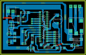
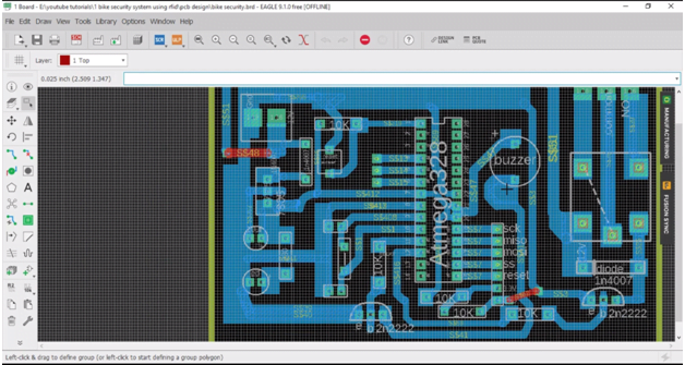
After I designed my PCB, using the Cadsoft eagle 9.1.0 version.
Amazon Links:
Arduino Nano USB-C Type (Recommended)
Other Tools and Components:
ESP32 WiFi + Bluetooth Module (Recommended)
Super Starter kit for Beginners
PCB small portable drill machines
*Please Note: These are affiliate links. I may make a commission if you buy the components through these links. I would appreciate your support in this way!
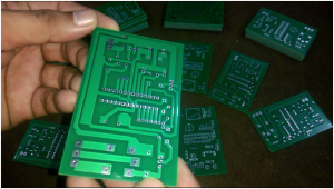
Then I sent my PCB Gerber files to WellPCB company, and make an order of 50 PCB’s. these are the PCB’s which I
just received.
properly documented containing all the information about the PCB’s. As you can see the quality is really great. I am 100% satisfied with their work.
Download this PCB board:
Bike anti theft PCB connections explanation:
Let’s start with the power supply, this is the terminal block where we connect the 12v and GND. wires. The 1n4007 diode is connected which protects the circuit if in case you connect the wires in the wrong way. The cathode side of the diode is connected with the input pin of the 7805 voltage regulator. As you can see clearly in the PCB design the Middle leg of the voltage regulator “7805” is connected with the ground.
A 330-ohm resistor is connected with the output of the regulator, this resistor is connected in series with the led anode side, this is a current limiting resistor, the other leg of the led is connected with the ground. A 10uf capacitor is also connected at the output of the voltage regulator.
A 10k resistor is connected with pin number 1 of the atmega328 controller and the other side of the 10-kilo ohm resistor is connected with the 5 volts. a 5-volt wire is also connected with pin number 7 of the controller. Pin number 8 of the controller is connected with the ground. A 16 MHz crystal is connected with pin 9 and pin 10 of the controller. 22pf capacitors are connected with the 16 MHz crystal.
Pin number 11 which is the digital pin 5 is connected with the 10-kilo-ohms resistor, and the other side of the 10-kilo ohm resistor is connected with the base of 2n2222 NPN transistor, the emitter is connected with the ground, while the collector is connected with the ground pin of the buzzer. This transistor will be used to control this buzzer.
While the buzzer positive pin is connected with the 5 volts. pin number 12 which is the digital pin 6 will be used to control a relay. The emitter is connected with the ground, while the collector is connected with one side of the relay coil while the other side of the relay coil is connected with 12 volts. This transistor is selected after the calculations, if you want to learn how to perform the relay driver circuit design calculation then you should watch my tutorial on relay driver circuit design calculations, You can find this tutorial on my YouTube channel “Electronic Clinic”. A diode is used across the relay coil for back emf protection. A terminal block is connected at the output of the relay. Digital pins 9 to 13 are connected with the RFID module. So that’s.
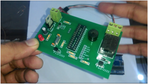
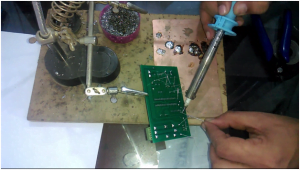
Soldering:
For the step by step explanation watch video at the end of this Article
MFRC522 RFID Module used in Bike Anti Theft system:
A few days back I posted a tutorial on ” Arduino MFRC522 RFID module Pinouts, Interfacing, how to read RFID tags identity number and use”
in this tutorial I covered all the basics, like interfacing, finding the identity numbers of the tags, I am using the same RFID tag. So if you don’t know how to find the RFID tag identity number then you should watch this tutorial. You can check out this video on my YouTube channel.
Bike anti theft system Arduino Programming:
|
1 2 3 4 5 6 7 8 9 10 11 12 13 14 15 16 17 18 19 20 21 22 23 24 25 26 27 28 29 30 31 32 33 34 35 36 37 38 39 40 41 42 43 44 45 46 47 48 49 50 51 52 53 54 55 56 57 58 59 60 61 62 63 64 65 66 67 68 69 70 71 72 73 74 75 76 77 78 79 80 81 82 83 84 85 86 87 88 89 90 91 92 93 94 95 96 97 98 99 100 101 102 103 104 105 106 107 108 109 110 111 112 113 114 115 116 117 118 119 120 121 122 123 |
/* ----------------------------------------------------------------------------- * Pin layout should be as follows: * Signal Pin Pin Pin * Arduino Uno Arduino Mega MFRC522 board * ------------------------------------------------------------ * Reset 9 5 RST * SPI SS 10 53 SDA * SPI MOSI 11 51 MOSI * SPI MISO 12 50 MISO * SPI SCK 13 52 SCK * voltage 3.3v */ #include <SPI.h> #include <MFRC522.h> #define SS_PIN 10 #define RST_PIN 9 MFRC522 mfrc522(SS_PIN, RST_PIN); // Create MFRC522 instance. int relay = 6; int flag = 0; int buzzer = 5; int relaystate = 0; void setup() { Serial.begin(9600); // Initialize serial communications with the PC pinMode(7,OUTPUT); pinMode(relay, OUTPUT); digitalWrite(relay, HIGH); pinMode(buzzer, OUTPUT); digitalWrite(buzzer, LOW); digitalWrite(7,LOW); SPI.begin(); // Init SPI bus mfrc522.PCD_Init(); // Init MFRC522 card //Serial.println("Scan a MIFARE Classic PICC to demonstrate Value Blocks."); } void loop() { relaystate = digitalRead(relay); // Prepare key - all keys are set to FFFFFFFFFFFFh at chip delivery from the factory. MFRC522::MIFARE_Key key; for (byte i = 0; i < 6; i++) { key.keyByte[i] = 0xFF; } // Look for new cards if ( ! mfrc522.PICC_IsNewCardPresent()) { return; } // Select one of the cards if ( ! mfrc522.PICC_ReadCardSerial()) { return; } // Now a card is selected. The UID and SAK is in mfrc522.uid. // Dump UID Serial.print("Card UID:"); for (byte i = 0; i < mfrc522.uid.size; i++) { // Serial.print(mfrc522.uid.uidByte[i] < 0x10 ? " 0" : " "); // Serial.print(mfrc522.uid.uidByte[i], DEC); } Serial.println(); // Dump PICC type byte piccType = mfrc522.PICC_GetType(mfrc522.uid.sak); // Serial.print("PICC type: "); //Serial.println(mfrc522.PICC_GetTypeName(piccType)); if ( piccType != MFRC522::PICC_TYPE_MIFARE_MINI && piccType != MFRC522::PICC_TYPE_MIFARE_1K && piccType != MFRC522::PICC_TYPE_MIFARE_4K) { //Serial.println("This sample only works with MIFARE Classic cards."); return; } // defining Cards here if( ((mfrc522.uid.uidByte[0] == 192) && (mfrc522.uid.uidByte[1] == 47) && (mfrc522.uid.uidByte[2] == 254) && (mfrc522.uid.uidByte[3] == 121))) { digitalWrite(relay, !relaystate); // Serial.println(relaystate); delay(2000); } if((relaystate == 0)&& (flag == 0) ) { // Serial.println("led on"); digitalWrite(buzzer, HIGH); delay(500); digitalWrite(buzzer, LOW); delay(500); digitalWrite(buzzer, HIGH); delay(500); digitalWrite(buzzer, LOW); delay(500); digitalWrite(buzzer, HIGH); delay(500); digitalWrite(buzzer, LOW); delay(500); flag = 1; } if((relaystate == 1)&& (flag == 1) ) { // Serial.println("led off"); digitalWrite(buzzer, HIGH); delay(500); digitalWrite(buzzer, LOW); delay(500); flag = 0; } else Serial.println("unregistered user"); } |




Hello, my tag is D7 43 76 60 where I put the code in the .ino file