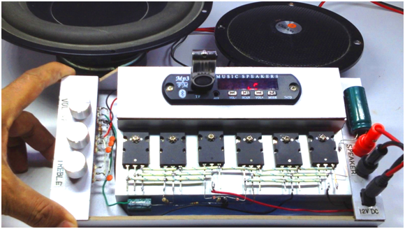
C5200 and A1943 amplifier with MP3 kit, Bluetooth, Volume, bass, and treble control
Last Updated on August 16, 2024 by Engr. Shahzada Fahad
Table of Contents
Description:
C5200 and A1943 amplifier- In this tutorial, you will learn how to make a powerful amplifier using the most popular C5200 and A1943 transistors. This is a DIY “Do It Yourself” level project. This powerful audio amplifier is based on a total of 6 transistors; I used 3 No’s C5200 NPN transistors and 3 No’s A1943 PNP transistors. These transistors are connected in parallel. The C5200 and A1943 transistors combination is widely used in high gain applications.
Unlike the most branded sound amplifiers, this amplifier is also provided with variable knobs for controlling the Volume, Bass, and Treble. Using these knobs the volume can be increased or decreased, the bass and treble can be adjusted as per the requirement. Moreover, an MP3 player kit is also added which allows the users to use USB flash drives/devices, Memory cards, and their mobile phones. Besides this, my designed amplifier has the Bluetooth facility as well, you can wireless connect your smart phone with the amplifier and play your favorite music.
There are a few more things which I would like to discuss, before I explain the making. While testing this amplifier I used a 12 Volts DC 5Amps from a PC Power Supply, but you can also use 12 volts to 18 volts DC power supply. The type of the speakers used are 4-ohms and 120 watts which gave me great sound with amazing sound quality.
Amazon Links:
*Disclosure: These are affiliate links. As an Amazon Associate I earn from qualifying purchases.
C5200 and A1943 Amplifier Circuit Diagram:
Following is the complete circuit diagram based on the C5200 and A1943 transistors.
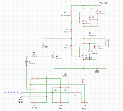
You can use any MP3 kit. You can see the connections are easy to follow; all the components are clearly labeled.
C5200 and A1943 amplifier making:
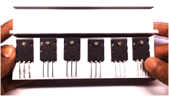
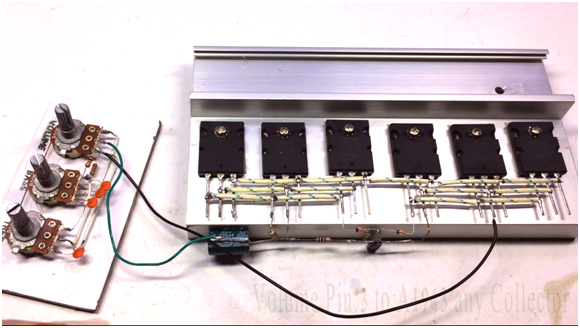
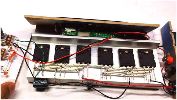
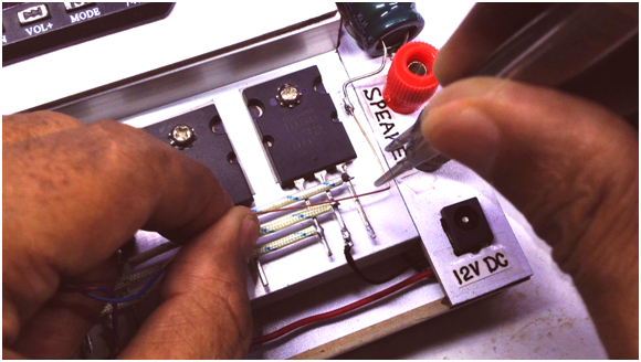
First, you will need a large heat sink which can accommodate 6 transistors. Next, if you have the thermal paste it would be really great, apply the thermal paste to all the 6 transistors and then place three 2SC5200 transistors on the left side and three 2SA1943 transistors on the right side. You should use (MICA) for proper insulation. The base plate should not touch with the heat sink as both the transistors have opposite polarity which will definitely result in a short circuit, which can permanently damage the transistors and other components. You have to options to protect this from a short circuit, you can use a proper insulation as I have already said, or you can use two heat sinks. If you want to save money and want to reduce the size then MICA is the best choice for you. Finally, I secured all the transistors with screws. You can see the whole arrangement in the following picture.
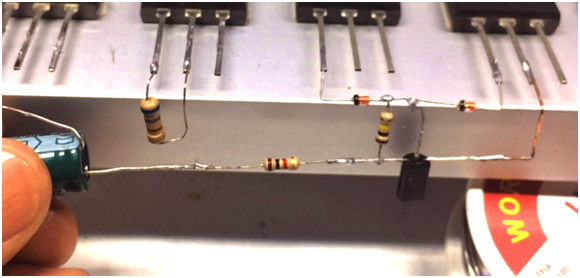
Now, solder two diodes 1N4148 in series so that the cathode of one diode is connected with the anode of the other diode. Now, solder the cathode leg of the diode with Pin 1 (base) of the 2SA1943 (right group), and solder the anode leg of the diode with pin 1 which is the base of the 2SC5200 (left group).
Connect collector of the 2SC2383 to the center joint of two 1N4148 diodes. Then solder 100k resistor from collector to base of 2SC2383. Connect emitter of 2SC2383 with the collector of 2SA1943 which later will be connected with the ground. Solder one end of 1k resistor to the base of 2SC2383 and the other end to the positive side of the 220uf electrolyte capacitor. Now, solder the last 680-ohm resistor between base-collector of 2SC5200.
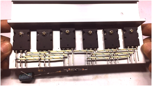
Connect each group of the transistors 2SC5200 & 2SA1943 in parallel i.e. connect all the three 2SC5200 transistors in parallel and then connect the remaining three transistors 2SA1943 in parallel. As you can see in the picture below, each group is connected in parallel. Finally, solder the emitters of both the groups together.
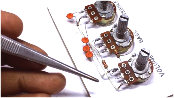
Complete the volume, bass and treble connections as per the following image or you can follow the connections shown in the circuit diagram above.
Connecting input & output sources
Take one black piece of connection wire. Solder one end of the connection wire to pin.3 of volume control and the other end to any collector pin of 2SA1943 for the ground connection. Connect one more wire of any color from the center pin of volume control to the negative side of 220uf electrolyte capacitor for the audio-in of the amplifier.
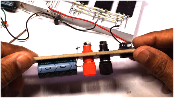
Solder power socket ground (black) wire to any collector pin of 2SA1943 transistors and positive (red) wire to any collector of 2SC5200.
Connect the audio out positive connection of mp3 kit to pin.1 of bass controller and negative (black) to the ground. Also provide 5 volts power supply to MP3 kit from any mobile charger or you can make your own 5V regulated power supply using 7805 voltage regulator, or you can also use the LM317t.
Take one 4700uf electrolyte capacitor and solder its positive end to the emitter (pin.3) of any 2SA1943 transistors and the other negative end will be connected to speaker’s socket. The other speaker’s black socket will be grounded.
One On/Off switch can be placed in between the positive supply in series which is optional. Plug-in the power supply, connect mobile with Bluetooth and enjoy the music.
I hope you have enjoyed reading this article. If you have any questions regarding this amplifier let me know in a comment. Read my other articles on Arduino related projects, digital electronics, PLC, Raspberry Pi, etc.
Related amplifier projects:
DIY One transistor Class A Audio Amplifier using 2SC5200
DIY D718 D882 amplifier homemade
2N3055 stereo amplifier homemade bluetooth diy
D718 B688 Powerful Amplifier DIY Homemade
Discover more from Electronic Clinic
Subscribe to get the latest posts sent to your email.


Dear Engn Fahad, Do we need a speaker protection circuit for this project inspite of the output caps.
Can this amplifier be done with out the 2SC2383 transistor?
2sc2383 is used in pre amplification stage where Avery weak signal is amplified to make it strong enough for further processing at the power amp stage….so the circuit eill not be strong without 2sc2383
How can I connect microphone preamp circuit with this?