LM317 Adjustable Regulator Power Supply Circuit calculator, Applications, & datasheet
Last Updated on August 23, 2024 by Engr. Shahzada Fahad
Table of Contents
LM317 Regulator, Description:
LM317 Adjustable Regulator- In this tutorial, you will learn how to make an adjustable variable voltage power supply based on the LM317 regulator. This tutorial explains everything you need to know about the LM317 Adjustable Regulator like for example
- LM317 voltage regulator comparison with 78xx Series of Regulators.
- LM317t price and its Amazon Purchase link.
- LM317 datasheet specifications.
- LM317 Power supply circuit diagram and calculations.
- LM317t Proteus simulation.
- LM317 applications.
- How to make 3.3V, 5V, 12V, and 24V regulated power supplies using the LM317 Regulator.
Without any further delay, let’s get started!!!
Amazon Purchase Links:
LM317T Variable Voltage Regulator:
Disclosure: These are affiliate links. As an Amazon Associate I earn from qualifying purchases.
LM317 Vs 78xx Series of Regulators:
The LM78xx series of regulators is quite famous throughout the world and are frequently used in millions of electronics-based projects. The 78xx series consists of the following regulators
LM7805
LM7806
LM7808
LM7809
LM7812
LM7815
LM7818 and
LM7824.
The 78 represents the series while the last two digits represent the voltage. Although we have this much variety of the voltage regulators then why we need the LM317 adjustable regulator?
There are some factors like the 78xx series of regulators give you the fixed voltage. I have been using the 7805 voltage regulator for powering up the 8051 family microcontrollers, ATmega328, and sensors that need 5 volts. The maximum of the sensors which are used with the Arduino are low power devices and they can be powered up using the 7805 voltage regulator. Another voltage regulator from the same series which is 7812; I have been using this voltage regulator for powering up a 12v relay and some small DC motors. No matter how many regulators are invented the 78xx series will always stay cool. But,
There are situations when we need variable voltage for example a workbench power supply. Or you are working on a project where you need 3.3 volts and current around 1 ampere. In a situation like this 78xx series of regulators fail to work or you will need complex circuit designing which trusts me nobody likes. A few months back I was working on a project in which I had to control the home appliance over wifi using the ESP8266 Wifi module. If you check the datasheet of the ESP8266 wifi module you will come to know that this module needs 3.3 volts and more current which cannot be supplied by the Arduino Uno. Although, the Arduino was able to provide 3.3 volts, but failed to provide more current.
In a situation like this for me, the best choice was to use the LM317t adjustable variable voltage regulator. So this tutorial is all about how to design a variable power supply using the LM317t voltage regulator. Before you plan to use any of the Electronic components it’s a good practice to first study the datasheet of the component you want to use, it gives you all the basic details. So first let’s have a look at its most important specs from the datasheet. You can also download the datasheet of the LM317t by clicking on the download button given below.
Download: LM317t datasheet: LM317 datasheet
LM317 adjustable regulator, datasheet specifications:
The LM317 is an adjustable 3-terminal positive voltage regulator capable of supplying in excess of 1.5 A over an output voltage range of 1.2 V to 37 Volts. This voltage regulator is exceptionally easy to use and requires only two external resistors to set the output voltage. Further, it employs internal current limiting; thermal shutdown and safe area compensation, making it essentially blow-out proof.
LM317 Features:
- Output Current in Excess of 1.5 A
- Output Adjustable between 1.2 V and 37 V
- Internal Thermal Overload Protection
- Internal Short Circuit Current Limiting Constant with Temperature
- Output Transistor Safe−Area Compensation
- Floating Operation for High Voltage Applications
- Eliminates Stocking many Fixed Voltages
- Available in Surface Mount
- NCV Prefix for Automotive and Other Applications Requiring
Unique Site and Control Change Requirements; AEC−Q100
Qualified and PPAP Capable
- These are Pb−Free Devices
LM317t Pinout Diagram:

Pin number1 is the adjust “Adj”
Pin number2 is the output “Vout”, and
Pin number3 is the Input “Vin”
LM317 variable voltage regulator circuit diagram Circuit Diagram:

The output voltage of the LM317t variable adjustable voltage regulator is determined by the ratio of two resistors R1 and R2 which basically forms a voltage divider circuit across the output terminal of the lm317t voltage regulator.
The voltage across the feedback resistor R1 is constant 1.25 volts reference voltage, Vref, produced between the output and adjustment terminal of the voltage regulator. The current is constant at the adjustment terminal which is 100uA. Since the reference voltage Vref across the resistor R1 is constant, so a constant currnet I will flow through the other resistor R2, which results in an output voltage which can be calculated using the following formula.
Vout = 1.25( 1 + (R2/R1) )
The input voltage Vin to the LM317t must be at least 2.5 volts greater than the required output voltage.
The voltage regulator LM317t has a very good load regulation providing that the minimum load is greater than 10mA. Now to maintain a constant reference voltage Vref of 1.25v, the minimum value of the feedback resistor R1 can be calculated as
1.25v / 10mA = 120 ohm’s
This value can actually range from 120 ohm’s to 1000 ohms with typical values of R1 being about 220 to 240 ohm’s for good stability. In my case I am going to use 214 ohm’s.
If we know the value of the required output voltage, let’s say 9 volts, and the feedback resistor R1 is 214 ohms, then we can calculate the value of resistor R2.
R1.((Vout/1.25)-1) = 214.((9/1.25)-1) = 1326 ohm
Of course in practice, the resistor R2 is normally replaced by a potentiometer so as to produce the variable voltage. Before starting the practical connections first I checked my connections in the Proteus Simulation software.
LM317t Proteus simulation Video:
For the Soldering watch video tutorial given at the end.
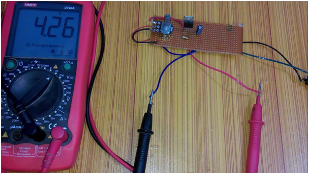
This is the final circuit after soldering. As you can see this circuit only has 4 components, a variable resistor which is R2 in the circuit diagram, a 214-ohm resistor represented by R1 in the circuit diagram, and a 33uf capacitor. These components are explained in the video given below.
This Final circuit is exactly as per the circuit diagram explained above. I connected the input power supply and at the output, I connected a digital multimeter. I was able to vary the voltage by rotating the knob of the variable resistor. So this project was a great success.
I designed this power supply for powering up my ESP8266 Wifi module. As it’s a variable power supply it can be used to power up so many different types of electronic components.
3.3V regulated voltage using LM317 regulator:
Before, we take a look at the circuit diagram, let’s discuss a few things that I believe you should know, the first question is Why we need 3.3V?
5 V became much used in early logic families, and especially TTL. While TTL is very much passé now everybody still talks about “TTL levels”. (I even hear UART described as “TTL bus”, which is a misnomer: it’s a logic level communication channel, but may well be a different voltage than 5 V.) In TTL 5 V was a good choice for the setpoints of the BJTs and for high noise immunity.
The 5 V level was retained when technology switched to HCMOS (High-Speed CMOS), with 74HC as the best-known family; 74HCxx ICs can operate at 5 V, but the 74HCT is TTL-compatible for its input levels as well. That compatibility may be required in mixed technology circuits, and that’s the reason why 5 V won’t be completely abandoned soon.
But HCMOS doesn’t need the 5 V like TTL’s bipolar transistors did. A lower voltage means lower power consumption: an HCMOS IC at 3.3 V will typically consume 50 % or less power than the same circuit at 5 V. So you create a microcontroller which internally runs at 3.3 V to save power, but has 5 V I/Os. (The I/O may also be 5 V-tolerant; then it works at the 3.3 V levels, but won’t be damaged by 5 V on its inputs. Next to compatibility 5 V also offers a better noise immunity.
And it goes further. I’ve worked with ARM7TDMI controllers (NXP LPC2100) with a core running on 1.8 V, with 3.3 V I/Os. The lower voltage is an extra power saving (only 13 % of a 5 V controller), and lower EMI as well. The drawback is that you need two voltage regulators.
So that’s the trend: internally ever lower voltages for lower power consumption and EMI, and externally a higher voltage for better noise immunity and connectivity.
If you check my category “IoT projects”, you will find that the Nodemcu ESP822 and the ESP32 both are based on the 3.3v controller boards. 3.3V is nowadays most frequently used for new controller boards and breakout boards, they are doing this is to reduce the size and the power consumption.
We also have a dedicated 3.3v regulator AMS1117. You can also use this regulator to get 3.3V. But, what if you have LM317T adjustable variable voltage regulator?
LM317 to output 3.3V:

C3 helps in ripple rejection up to 15dB
D1 protects the device against input short circuit
D2 protects against output short circuit for capacitance discharging
C2 of 1uF tantalum capacitor on the output helps to improve transient response.
5V regulated Voltage using LM317 Regulator:
We need 5V to power up different controller boards; starting with the Arduino Uno, Arduino Nano, and so on. All these controller boards need 5V. The IoT supported devices e.g. Nodemcu ESP8266, and ESP32 Wifi + Bluetooth Module also can be powered up using the 5V. The Nodemcu and ESP32 both are 3.3V supported controller boards. The boards are provided with the 3.3V regulators.
There are thousands of sensors and electronic devices that need 5V. You can use the most famous linear voltage regulator LM7805 to get the regulated 5V and you can also use the LM317 regulator to get the regulated 5V.
LM317 to output 5V:
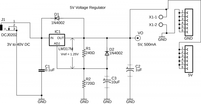
C3 helps in ripple rejection up to 15dB
D1 protects the device against input short circuit
D2 protects against output short circuit for capacitance discharging
C2 of 1uF tantalum capacitor on the output helps to improve transient response.
LM317 based 5V regulated power supply Proteus Simulation:
I tested this circuit in the Proteus simulation software. You can download the simulation file if you want to check this for yourself, or want to do some modifications, or you need this for your project reports.
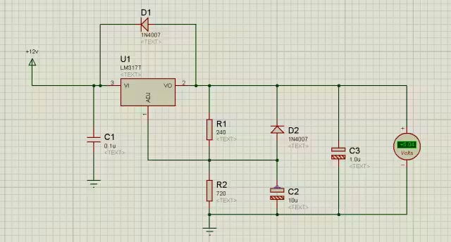
After testing the simulation, next I designed the PCB board using the CadSoft Eagle Schematic and PCB designing Software. The download link of the PCB board layout is given below.

Download the original PCB board:
12V regulated Voltage using LM317 Regulator:
We need a 12V power supply for controlling relays, small dc motors, and other electronic circuits.

C3 helps in ripple rejection up to 15dB
D1 protects the device against input short circuit
D2 protects against output short circuit for capacitance discharging
C2 of 1uF tantalum capacitor on the output helps to improve transient response.
24V regulated Voltage using LM317 Regulator:
24V power supply is not very popular and is used very rarely in electronics circuits. Although you need 24Volts for an electrical bike or wheelchair, trust me the voltage regulator like the LM317 is not used in such projects. For electric bikes and wheelchairs, you need high Amps. But anyhow, you can also get a 24V regulated voltage using the LM317 Adjustable Variable Voltage Regulator.

C3 helps in ripple rejection up to 15dB
D1 protects the device against input short circuit
D2 protects against output short circuit for capacitance discharging
C2 of 1uF tantalum capacitor on the output helps to improve transient response.
Variable Voltage using LM317 Regulator:

The circuit diagram is almost the same, but this time the R2 is a variable resistor or Potentiometer. Using this potentiometer we can set different voltages.
Watch Video Tutorial:
Discover more from Electronic Clinic
Subscribe to get the latest posts sent to your email.