Control multiple loads using only one button and a Potentiometer, Arduino Project
Last Updated on September 21, 2024 by Engr. Shahzada Fahad
Table of Contents
Control multiple Loads:
Control multiple loads using only one button and a Potentiometer- In this article, you will learn how to control multiple electrical loads using only 1 button and a potentiometer. You may find this idea strange, but believe me, going forward you will understand its benefits.
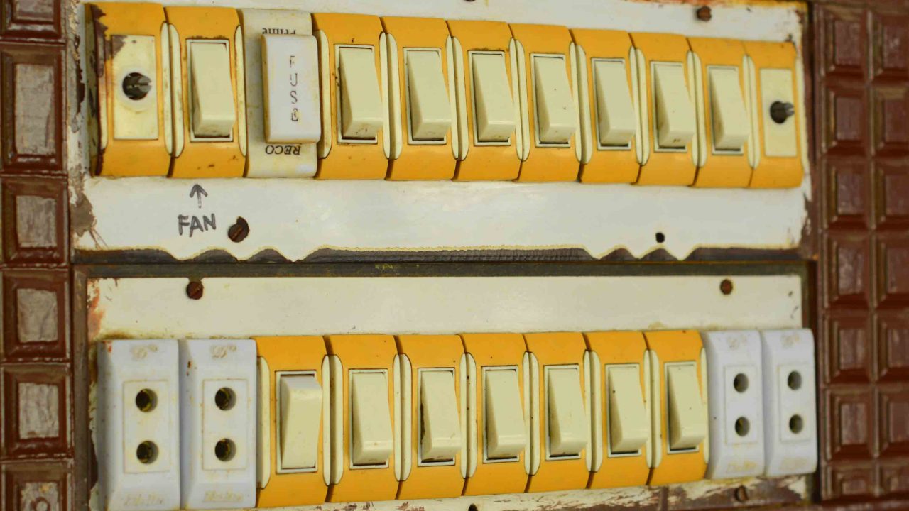
You must have seen big switchboards in homes. In which many switches are installed to control different loads. You know very well that 99% of switchboards do not use any microcontrollers inside. So in such a situation, you can install as many switches as you want. It doesn’t matter.
The difference comes when we use a microcontroller to control multiple loads. Microcontrollers have limited input/output pins. So, we have to be very careful while using the controller pins. So that we have more pins left to control the electrical loads and to connect other sensors. Nowadays it is a very common practice let’s say that if we have to control 8 electrical devices, we simply install 8 switches. Due to this, the pins of the microcontroller are wasted.
On the other hand, if we use Bluetooth and an android app, then we need only 2 pins on the controller side. We can send multiple control commands with the help of serial communication. We can add as many buttons as we want to an Android application. While the input pins on the controller side will remain the same.
Similarly, we can use the HMI screen. So that the pins of the controller are used as little as possible. And we can control as many electrical devices as possible.
No doubt using Android apps or HMI screens reduces the use of controller pins, but the bulk of the programming work increases, and obviously, the price also goes up.
So that’s why I thought why not make a very simple control system for those people who can’t afford an HMI screen? Or they don’t want to get into the hassle of Android application designing.
First, let me share with you the test results of my designed simple control system; so that you can have an idea of how beneficial it can be.

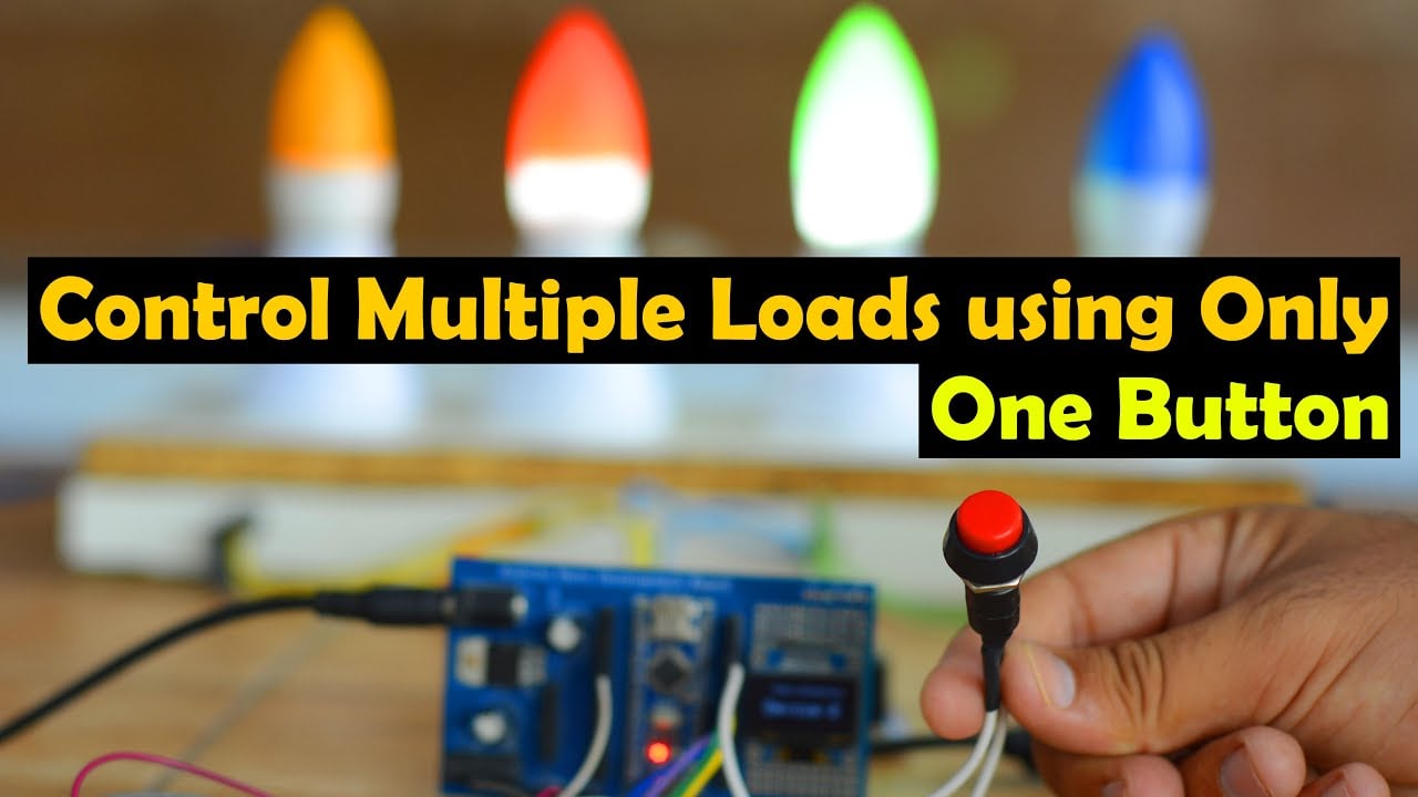
You can see a button and a potentiometer, using these, I am going to control certain loads. For demonstration purposes, I have connected 4 bulbs, which are connected to 4 relays. Besides lights, you can use any other 110/220Vac loads or use any other DC type loads.
If you want to use 110/220Vac supply, you must not forget to use protective gloves, because 110/220Vac can prove fatal. So, as far as possible you must ensure the presence of a friend or any companion while carrying on work on such projects. When the AC supply is ON, do not touch the relay module.
By rotating the knob of the potentiometer “Pot” you can select the device and then using the switch/Button you can turn ON or turn OFF that device.

First I selected Bulb3 using the Potentiometer and then I used the button to turn ON the Light.
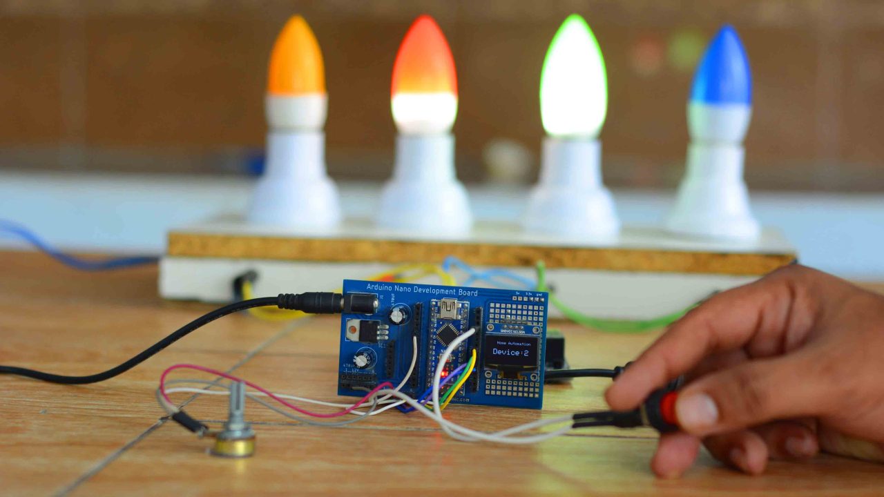
Similarly, I selected Device 2. I can randomly select any device/light and then using the button I can turn it ON or turn it OFF.
Apart from controlling the electrical loads you can also use this technique to scroll through different menu items. Anyway, instead of displaying the device number, you can also print the exact name of the device which you want to control.
I am sure by now, you might have got an idea of how does this system work. So, without any further delay let’s get started!!!
Amazon Links:
Arduino Nano USB-C Type (Recommended)
*Disclosure: These are affiliate links. As an Amazon Associate I earn from qualifying purchases.
Arduino Multiple Loads, Circuit:

- Connect the middle leg of the potentiometer with Analog A1 of the Arduino Nano
- Connect the leftmost and rightmost pins of the potentiometer with the 5V and GND pins of the Arduino.
SSD1306 Oled display Connections
- Connect VCC of the OLED with 3.3V of the Arduino Nano
- Connect ground of the OLED with ground of the Arduino Nano
- Connect the SDA pin of the OLED with A4 pin of the Arduino Nano
- Connect the SCL pin of the OLED with A5 pin of the Arduino Nano
4-channel relay module connections:
- Connect the input1, input2, input3, and input4 of the relay module with the digital pin 2, 3, 4, and 5 of the Arduino Nano respectively.
- Connect the VCC of the relay module with the 5V of the Arduino Nano
- Connect the ground of the relay module with the ground of the Arduino Nano
Now we will connect four bulbs with the relay module such that:
- Connect the Neutral of the AC supply with all four bulbs.
- Then connect the live wire of the AC supply with the common of all four relays
- Then connect the other contacts of the bulbs with the Normally Open (NO) of the relays.
Finally, connect a push button with digital pin 9 of the Arduino Nano.
Using the Altium Designer software, I designed the Arduino Development board and 4 channel Relay module PCBs. I Generated the Gerber files and placed an online order on the JLCPCB official website.
Download Gerber files:
Arduino Nano Development Board
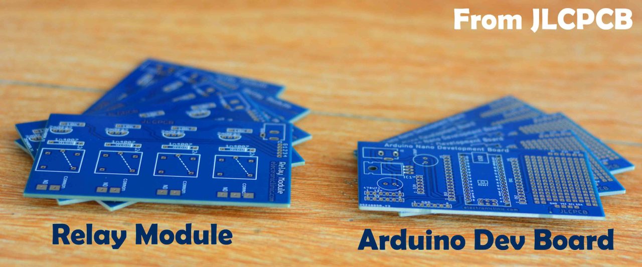
These are the PCB boards that I received from the JLCPCB as you can see the quality is really great. The silkscreen is quite clear and the Blue Color Solder mask looks amazing. On the right side is the Arduino Nano development board PCBs and on the left side is the 4-channel relay module PCBs. Next, I started off by placing the components and completed the soldering job.
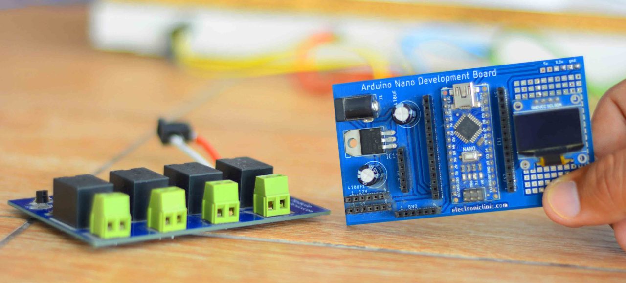
This is how the PCB boards look after soldering all the components.
Control Multiple Loads, Code:
Before, you start the programming, first of all, make sure you download the Adafruit_GFX and Adafruit_SSD1306 libraries.
libraries
Code:
|
1 2 3 4 5 6 7 8 9 10 11 12 13 14 15 16 17 18 19 20 21 22 23 24 25 26 27 28 29 30 31 32 33 34 35 36 37 38 39 40 41 42 43 44 45 46 47 48 49 50 51 52 53 54 55 56 57 58 59 60 61 62 63 64 65 66 67 68 69 70 71 72 73 74 75 76 77 78 79 80 81 82 83 84 85 86 87 88 89 90 91 92 93 94 95 96 97 98 99 |
#include <Wire.h> #include <Adafruit_GFX.h> #include <Adafruit_SSD1306.h> int Relay1 = 2; // relay1 int Relay2 = 3; // relay2 int Relay3 = 4; // relay3 int Relay4 = 5; // relay4 int switchPin = 9; // Push button / switch int pot1 = A1; // Potentiometer boolean lastButton; boolean currentButton = false; boolean RelayOn = false; // Oled display #define SCREEN_WIDTH 128 // OLED display width, in pixels #define SCREEN_HEIGHT 64 // OLED display height, in pixels // Declaration for an SSD1306 display connected to I2C (SDA, SCL pins) #define OLED_RESET -1 // Reset pin # (or -1 if sharing Arduino reset pin) Adafruit_SSD1306 display(SCREEN_WIDTH, SCREEN_HEIGHT, &Wire, OLED_RESET); void setup() { Serial.begin(9600); pinMode(switchPin, INPUT_PULLUP); // switch as input pinMode(Relay1, OUTPUT); pinMode(Relay2, OUTPUT); pinMode(Relay3, OUTPUT); pinMode(Relay4, OUTPUT); pinMode(pot1,INPUT); display.begin(SSD1306_SWITCHCAPVCC, 0x3C); delay(2000); display.clearDisplay(); display.setTextColor(WHITE); } //debounce function to stabilise the button boolean debounce(boolean last) { boolean current = digitalRead(switchPin); if (last != current) { delay(5); current = digitalRead(switchPin); } return current; } void loop() { int potvalue = analogRead(pot1); // Reads the potentiometer //Serial.println(potvalue); //Serial.print("select node = "); int count = map(potvalue, 0, 786, 1, 4); // Limit the range Serial.println(count); display.clearDisplay(); display.setCursor(25,10); display.setTextSize(1); display.setTextColor(WHITE); display.print("Home Automation"); display.setCursor(15,30); display.setTextSize(2); display.setTextColor(WHITE); display.print("Device:"+String(count)); display.display(); lastButton = currentButton; currentButton = debounce(lastButton); if (lastButton == false && currentButton == true) { if (count == 1) { RelayOn = !RelayOn; digitalWrite(Relay1, RelayOn); } else if (count == 2) { RelayOn = !RelayOn; digitalWrite(Relay2, RelayOn); } else if (count == 3) { RelayOn = !RelayOn; digitalWrite(Relay3, RelayOn); } else if (count == 4) { RelayOn = !RelayOn; digitalWrite(Relay4, RelayOn); } } } |
This is a simple program and won’t find anything complicated. Maximum of the code is well commented. The purpose of this code is to read the potentiometer and then to map the values as per the number of devices. As in my case, I am controlling 4 electrical loads so that’s why I am using the maximum limit 4. These other instructions are used to print the text and device number on the Oled display module.
Finally, using some if conditions we turn ON and Turn OFF the relays as per the last button and current button status. So, that’s all about the programming.
Watch Video Tutorial
Discover more from Electronic Clinic
Subscribe to get the latest posts sent to your email.


Kindly tellme any multinational company to work hard for future growth.