ESP32-S3 Real-Time IMU Dashboard Using LVGL & SquareLine Studio
Last Updated on September 10, 2026 by Engr. Shahzada Fahad
Table of Contents
Description:
Real-time IMU dashboard:
This is NOT an SPI display.
What you are looking at is a parallel TFT, and that’s exactly why it’s so fast and buttery smooth. In this project, we build an ESP32-S3 IMU dashboard that displays real-time accelerometer, gyroscope, and temperature data using LVGL and SquareLine Studio.
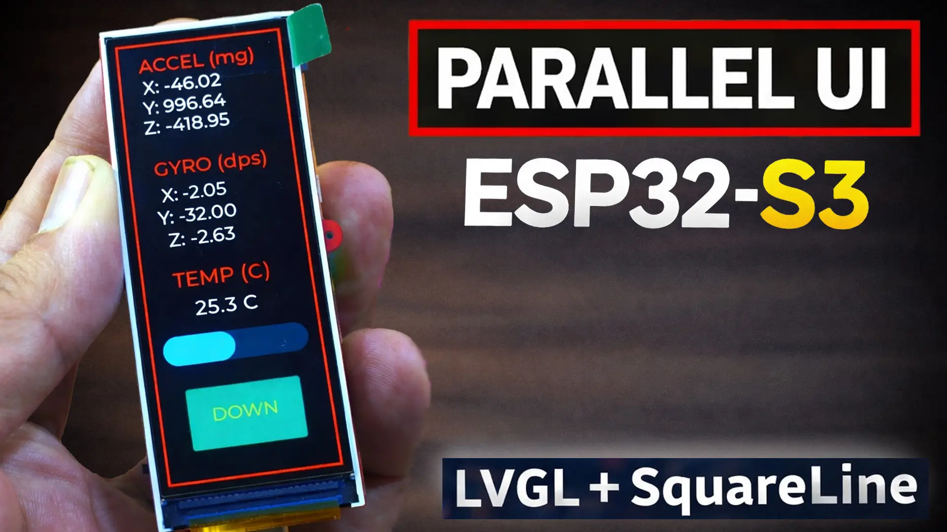
This is the Makerfabs MaTouch ESP32-S3 Parallel TFT 3.16-inch ST7701S development kit, and the UI you are seeing right now was not coded line by line.
Why use an Arduino with an MPU6050 and waste so much time on wiring and slow processing, when you can have an IMU, gyroscope, microphone, speaker, micro SD card slot, RTC chip, temperature sensor, a 3.16-inch display, and the powerful ESP32-S3 with WiFi and Bluetooth 5.0; all on a single board, and far better in almost every way than an Arduino?
Arduino is great! But let’s be honest.

If you were to buy and wire all these modules separately with an Arduino or ESP32, it would cost more money and take a lot of time just to connect everything. So why waste time and money on something you already get on one board?
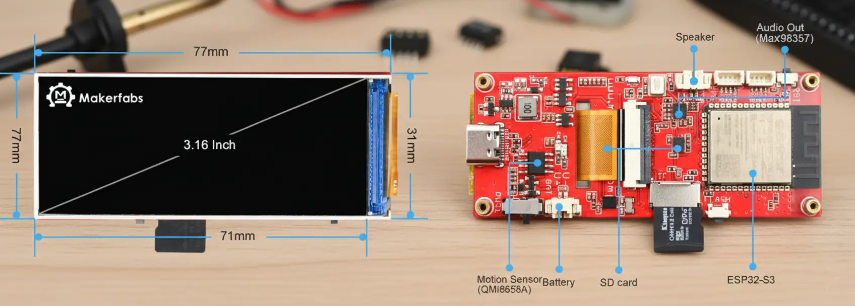
Instead, you can spend that time experimenting, learning, and building new ideas.
This board is completely portable. It has a built-in lithium battery holder, and you don’t have to worry about safe charging because it comes with an onboard charging circuit that takes care of everything automatically. So many features packed into such a tiny board; it’s honestly incredible.
And when you compare the size, it’s much smaller than an Arduino setup with external modules.
It’s ready to use right out of the box and designed for the most advanced projects, like…
Gesture controlled Robotic Car.
Digital Spirit Level or Bubble level.
Gesture controlled MP3 Player.
Mini Photo Album.
Self Balancing Robot
Sensor Monitoring.
Home automation.
As a portable receiver for monitoring important processes.
Real-time digital clock
Vibration monitoring
Time controlled loads
Steps counter
Voice recorder
Dash board
Earth-quack monitoring
This can be a long list of projects, the possibilities with this development board are endless.
And the most amazing part is that you can create a completely mind-blowing UI in just a few minutes using SquareLine Studio and LVGL.
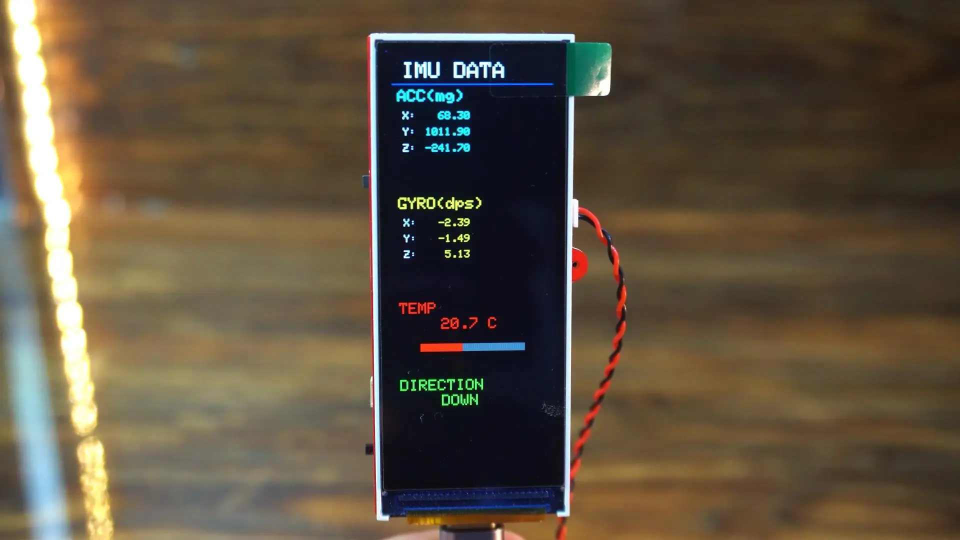
This is a built-in example, where you have to configure every single element through code. Implementing a custom design this way can easily take hours; or sometimes even days; just to get the exact look you want.
Now, when I did the same thing using SquareLine Studio and LVGL, I didn’t have to write a single line of code for the UI design.
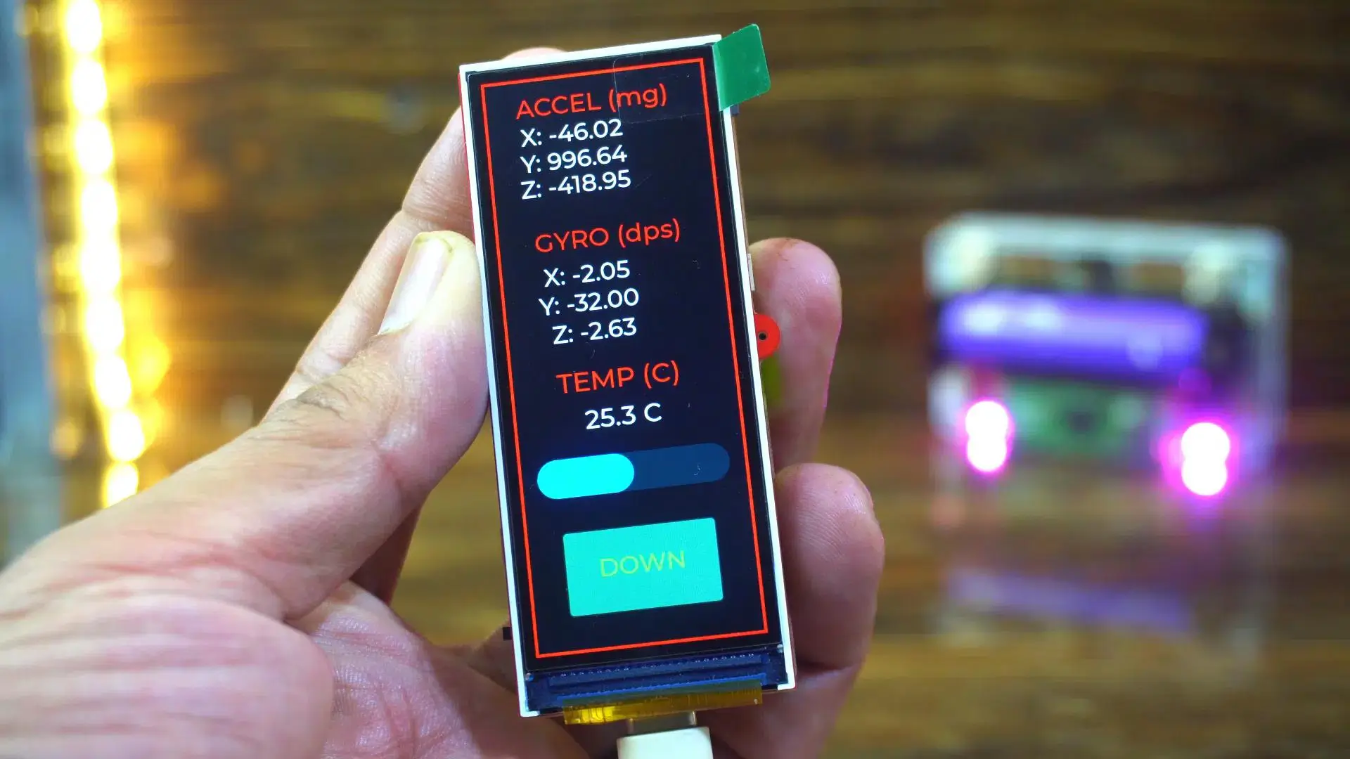
Everything was done in one go. In SquareLine Studio, you can see the entire interface in advance, in real time, so there’s no guessing at all. You already know exactly how your final design is going to look.
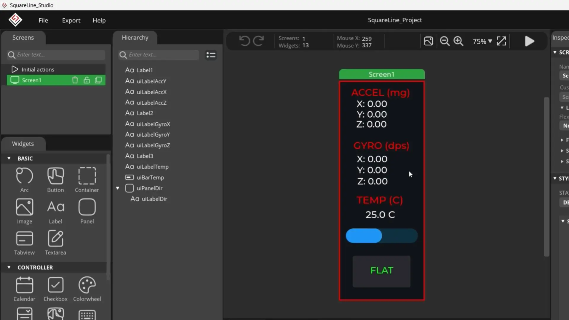
So in this article, I am going to explain how to program this amazing development board using Arduino IDE, SquareLine Studio, and LVGL, step by step.
And if you want ready-to-use project folders, including all the UI files and other resources, you can visit my Patreon page. With just a $1 subscription, you will get access to all these amazing projects.
Software Setup and Libraries:
Before starting the project, I want to share my software setup and the libraries I am using. As you can see, I am currently working with Arduino IDE version 2.3.6 and the ESP32 boards package version 2.0.11. If you want, you can also try version 2.0.16.
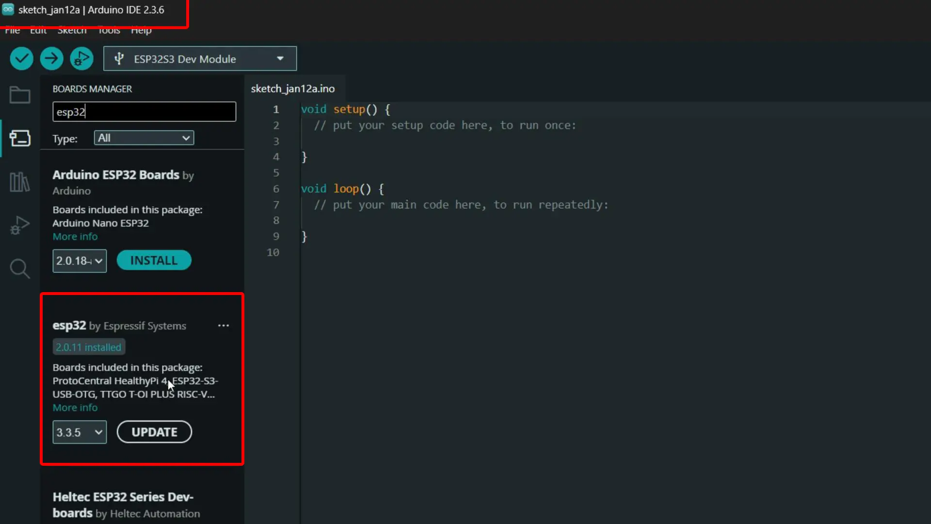
Now let’s talk about the libraries.
First, you will need the Arduino_GFX_Library from Makerfabs. I have already explained how to use this library in the getting started video and article, so if you haven’t read that yet, make sure to check it out.
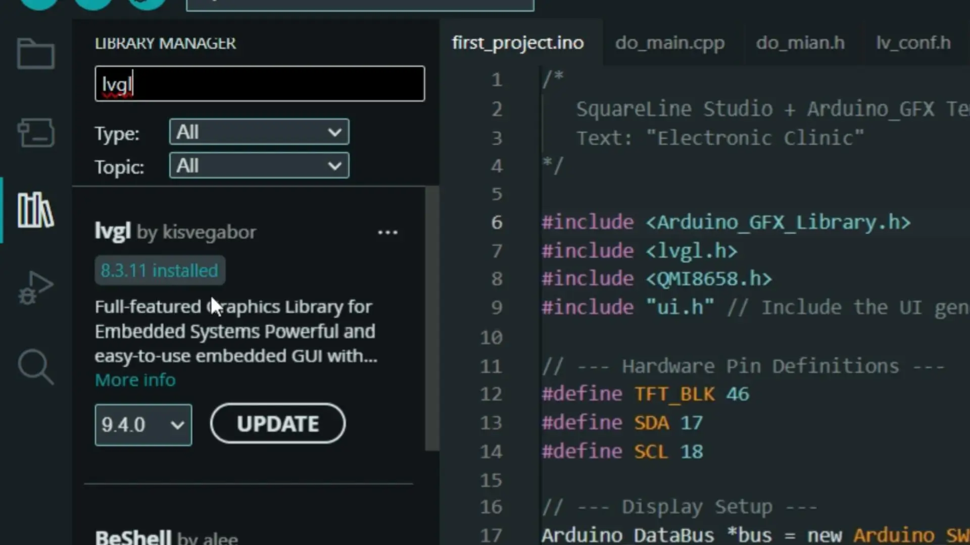
Next, you will also need the LVGL library. To install it, go to the Library Manager… search for LVGL and install it… As you can see, I already have LVGL version 8.3.11 installed.
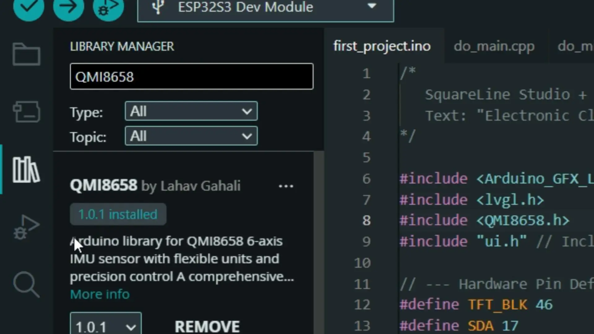
You will also need to install the QMI8658 library, which is used for the IMU and gyroscope. As you can see, I have already installed version 1.0.1.
WHY SQUARELINE SAVES TIME:
The code you are seeing right now is the same code that I showed in the getting started video, and as you can see, it’s quite long.
Code from MakerFabs:
|
1 2 3 4 5 6 7 8 9 10 11 12 13 14 15 16 17 18 19 20 21 22 23 24 25 26 27 28 29 30 31 32 33 34 35 36 37 38 39 40 41 42 43 44 45 46 47 48 49 50 51 52 53 54 55 56 57 58 59 60 61 62 63 64 65 66 67 68 69 70 71 72 73 74 75 76 77 78 79 80 81 82 83 84 85 86 87 88 89 90 91 92 93 94 95 96 97 98 99 100 101 102 103 104 105 106 107 108 109 110 111 112 113 114 115 116 117 118 119 120 121 122 123 124 125 126 127 128 129 130 131 132 133 134 135 136 137 138 139 140 141 142 143 144 145 146 147 148 149 150 151 152 153 154 155 156 157 158 159 160 161 162 163 164 165 166 167 168 169 170 171 172 173 174 175 176 177 178 179 180 181 182 183 184 185 186 187 188 189 190 191 192 193 194 195 196 197 198 199 200 201 202 203 204 205 206 207 208 209 210 211 212 213 214 215 216 217 218 219 220 221 222 223 224 225 226 227 228 229 230 231 232 233 234 235 236 237 238 239 240 241 242 243 244 245 246 247 248 249 250 251 252 253 254 255 256 257 258 259 260 261 262 263 264 265 266 267 268 269 270 271 272 273 274 275 276 277 278 279 280 281 282 283 284 285 286 287 288 289 290 291 292 293 294 295 296 297 298 299 300 301 302 303 304 305 306 307 308 309 310 311 312 313 314 315 316 317 318 319 320 321 322 323 324 325 326 327 328 329 330 331 332 333 334 335 336 337 338 339 340 341 342 343 344 345 346 347 348 349 350 351 352 353 354 355 356 357 358 359 360 361 362 363 364 365 366 367 368 369 370 371 372 373 374 375 376 377 378 379 380 381 382 383 384 385 386 387 388 389 390 391 392 393 394 395 396 397 398 399 400 401 402 403 404 405 406 407 408 409 410 411 412 413 414 415 416 417 418 419 420 421 422 423 424 425 426 427 428 429 430 431 432 433 434 435 436 437 438 439 440 441 442 443 444 445 446 447 448 449 450 451 452 453 454 455 456 457 458 459 460 461 462 463 464 465 466 467 468 469 470 471 472 473 474 475 476 477 478 479 480 481 482 483 484 485 486 487 488 489 490 491 492 493 494 495 496 497 498 499 500 501 502 503 504 505 506 507 508 509 510 511 512 513 514 515 516 517 518 519 520 521 522 523 524 525 526 527 528 529 530 531 532 533 534 535 536 537 538 539 540 541 542 543 544 545 546 547 548 549 550 551 552 553 554 555 556 557 558 559 560 561 562 |
/* Library version: Arduino IDE 2.3.6 esp32 V2.0.16 GFX Library for Arduino v1.3.8 QMI8658 v1.0.1 Tools: USB CDC On Boot: Enabled Flash size:16MB(128Mb) Partition Schrme:16M Flash(3MB APP/9.9MB FATFS) PSRAM: OPI PSRAM */ #include <Arduino_GFX_Library.h> #include <QMI8658.h> #define TFT_BLK 46 #define SDA 17 #define SCL 18 Arduino_DataBus *bus = new Arduino_SWSPI( GFX_NOT_DEFINED /* DC */, 45 /* CS */, 39 /* SCK */, 40 /* MOSI */, GFX_NOT_DEFINED /* MISO */); Arduino_ESP32RGBPanel *rgbpanel = new Arduino_ESP32RGBPanel( 7 /* DE */, 4 /* VSYNC */, 5 /* HSYNC */, 6 /* PCLK */, 12 /* R0 */, 11 /* R1 */, 8 /* R2 */, 16 /* R3 */, 15 /* R4 */, 0 /* G0 */, 14 /* G1 */, 10 /* G2 */, 9 /* G3 */, 3 /* G4 */, 13 /* G5 */, 48 /* B0 */, 47 /* B1 */, 1 /* B2 */, 21 /* B3 */, 41 /* B4 */, 1 /* hsync_polarity */, 10 /* hsync_front_porch */, 8 /* hsync_pulse_width */, 50 /* hsync_back_porch */, 1 /* vsync_polarity */, 10 /* vsync_front_porch */, 8 /* vsync_pulse_width */, 20 /* vsync_back_porch */); Arduino_RGB_Display *gfx = new Arduino_RGB_Display( 320 /* width */, 820 /* height */, rgbpanel, 0 /* rotation */, true /* auto_flush */, bus, GFX_NOT_DEFINED /* RST */, st7701_type9_init_operations, sizeof(st7701_type9_init_operations)); // Create QMI8658 instance QMI8658 imu; // 0-->flat 1-->left 2-->right 3-->up 4-->down int Direction = 0; // UI Color #define BACKGROUND BLACK #define TEXT_COLOR WHITE #define ACCEL_COLOR CYAN #define GYRO_COLOR YELLOW #define TEMP_COLOR RED #define DIRECTION_COLOR GREEN // UI Positions #define TITLE_Y 20 #define ACCEL_Y 100 #define GYRO_Y 300 #define TEMP_Y 500 #define DIRECTION_Y 650 void setup() { Serial.begin(115200); Serial.println("QMI8658 Demo"); pinMode(TFT_BLK, OUTPUT); digitalWrite(TFT_BLK, LOW); if (!imu.begin(SDA, SCL)) { Serial.println("Failed to initialize QMI8658!"); while (1) { Serial.println("Retrying in 5 seconds..."); delay(5000); } } /*Set accelerometer range ±2g:高精度测量,适合微小振动、倾角检测 ±4g:一般运动检测 ±8g:剧烈运动、机器人、无人机(推荐通用用途) ±16g:冲击检测、汽车碰撞测试 */ imu.setAccelRange(QMI8658_ACCEL_RANGE_2G); /*Set accelerometer output data rate 8-64Hz:省电模式,静态监测 250Hz:一般运动、步数计数 500Hz:游戏控制器、手势识别 1000Hz:高速运动、振动分析、无人机 */ imu.setAccelODR(QMI8658_ACCEL_ODR_500HZ); /*Set gyroscope range ±16-64dps:缓慢旋转、倾角检测 ±128-256dps:一般转动、机器人导航 ±512dps:快速转动、无人机、运动检测(推荐通用用途) ±1024-2048dps:极高速旋转、特技飞行 */ imu.setGyroRange(QMI8658_GYRO_RANGE_32DPS); /*Set gyroscope output data rate*/ imu.setGyroODR(QMI8658_GYRO_ODR_250HZ); // Set units (DEFAULT: mg for accel, dps for gyro - matches most IMU displays) imu.setAccelUnit_mg(true); // Use mg (like your screen: ACC_X = -965.82) imu.setGyroUnit_dps(true); // Use dps (degrees per second) imu.setDisplayPrecision(6); // 6 decimal places (like your screen) // Alternative ways to set units: // imu.setAccelUnit_mps2(true); // Would use m/s² instead of mg // imu.setGyroUnit_rads(true); // Would use rad/s instead of dps // imu.setDisplayPrecision(QMI8658_PRECISION_4); // 4 decimal places // Enable sensors imu.enableSensors(QMI8658_ENABLE_ACCEL | QMI8658_ENABLE_GYRO); gfx->begin(); drawStaticUI(); } void loop() { QMI8658_Data sensorData; if (imu.readSensorData(sensorData)) { // Determine direction int newDirection = Direction; if(sensorData.accelX <= -300) newDirection = 1; else if(sensorData.accelX > 300) newDirection = 2; else if(sensorData.accelY <= -300) newDirection = 3; else if(sensorData.accelY > 300) newDirection = 4; else if(sensorData.accelX > -200 && sensorData.accelX < 200 && sensorData.accelY > -200 && sensorData.accelY < 200) newDirection = 0; // Update UI updateSensorData(sensorData); if(newDirection != Direction) { Direction = newDirection; updateDirection(Direction); } } } void drawStaticUI() { // Title gfx->setTextSize(4); gfx->setTextColor(TEXT_COLOR); gfx->setCursor(30, TITLE_Y); gfx->println("IMU DATA"); // Line under title gfx->drawFastHLine(10, TITLE_Y + 40, 300, BLUE); // Accelerometer title gfx->setTextSize(3); gfx->setTextColor(ACCEL_COLOR); gfx->setCursor(20, ACCEL_Y - 30); gfx->println("ACC(mg)"); // Gyroscope title gfx->setTextColor(GYRO_COLOR); gfx->setCursor(20, GYRO_Y - 30); gfx->println("GYRO(dps)"); // Temperature title gfx->setTextColor(TEMP_COLOR); gfx->setCursor(20, TEMP_Y - 30); gfx->println("TEMP"); // Direction title gfx->setTextColor(DIRECTION_COLOR); gfx->setCursor(20, DIRECTION_Y - 30); gfx->println("DIRECTION"); // Labels for accelerometer and gyroscope gfx->setTextSize(2); gfx->setTextColor(WHITE); gfx->setCursor(30, ACCEL_Y + 10); gfx->println("X:"); gfx->setCursor(30, ACCEL_Y + 40); gfx->println("Y:"); gfx->setCursor(30, ACCEL_Y + 70); gfx->println("Z:"); gfx->setCursor(30, GYRO_Y + 10); gfx->println("X:"); gfx->setCursor(30, GYRO_Y + 40); gfx->println("Y:"); gfx->setCursor(30, GYRO_Y + 70); gfx->println("Z:"); } void updateSensorData(const QMI8658_Data &data) { // Update accelerometer data gfx->setTextSize(2); gfx->setTextColor(ACCEL_COLOR); gfx->fillRect(60, ACCEL_Y + 10, 200, 25, BACKGROUND); gfx->setCursor(60, ACCEL_Y + 10); gfx->printf("%8.2f", data.accelX); gfx->fillRect(60, ACCEL_Y + 40, 200, 25, BACKGROUND); gfx->setCursor(60, ACCEL_Y + 40); gfx->printf("%8.2f", data.accelY); gfx->fillRect(60, ACCEL_Y + 70, 200, 25, BACKGROUND); gfx->setCursor(60, ACCEL_Y + 70); gfx->printf("%8.2f", data.accelZ); // Update gyroscope data gfx->setTextColor(GYRO_COLOR); gfx->fillRect(60, GYRO_Y + 10, 200, 25, BACKGROUND); gfx->setCursor(60, GYRO_Y + 10); gfx->printf("%8.2f", data.gyroX); gfx->fillRect(60, GYRO_Y + 40, 200, 25, BACKGROUND); gfx->setCursor(60, GYRO_Y + 40); gfx->printf("%8.2f", data.gyroY); gfx->fillRect(60, GYRO_Y + 70, 200, 25, BACKGROUND); gfx->setCursor(60, GYRO_Y + 70); gfx->printf("%8.2f", data.gyroZ); // Update temperature data gfx->setTextColor(TEMP_COLOR); gfx->setTextSize(3); gfx->fillRect(100, TEMP_Y, 150, 40, BACKGROUND); gfx->setCursor(100, TEMP_Y); gfx->printf("%.1f C", data.temperature); // Update temperature bar int tempBarWidth = map(constrain(data.temperature, 0, 50), 0, 50, 0, 200); gfx->fillRect(60, TEMP_Y + 50, 200, 15, DARKGREY); gfx->fillRect(60, TEMP_Y + 50, tempBarWidth, 15, RED); } void updateDirection(int dir) { gfx->setTextSize(3); gfx->setTextColor(DIRECTION_COLOR); gfx->fillRect(80, DIRECTION_Y, 150, 40, BACKGROUND); switch(dir) { case 1: // Left gfx->setCursor(100, DIRECTION_Y); gfx->println("LEFT"); break; case 2: // Right gfx->setCursor(100, DIRECTION_Y); gfx->println("RIGHT"); break; case 3: // Up gfx->setCursor(100, DIRECTION_Y); gfx->println("UP"); break; case 4: // Down gfx->setCursor(100, DIRECTION_Y); gfx->println("DOWN"); break; case 0: // Flat gfx->setCursor(100, DIRECTION_Y); gfx->println("FLAT"); break; } } |
Just imagine how many times you would have to tweak and recompile it to create a UI design of your own choice, because everything has to be done entirely through programming. Let me show you its output one more time.
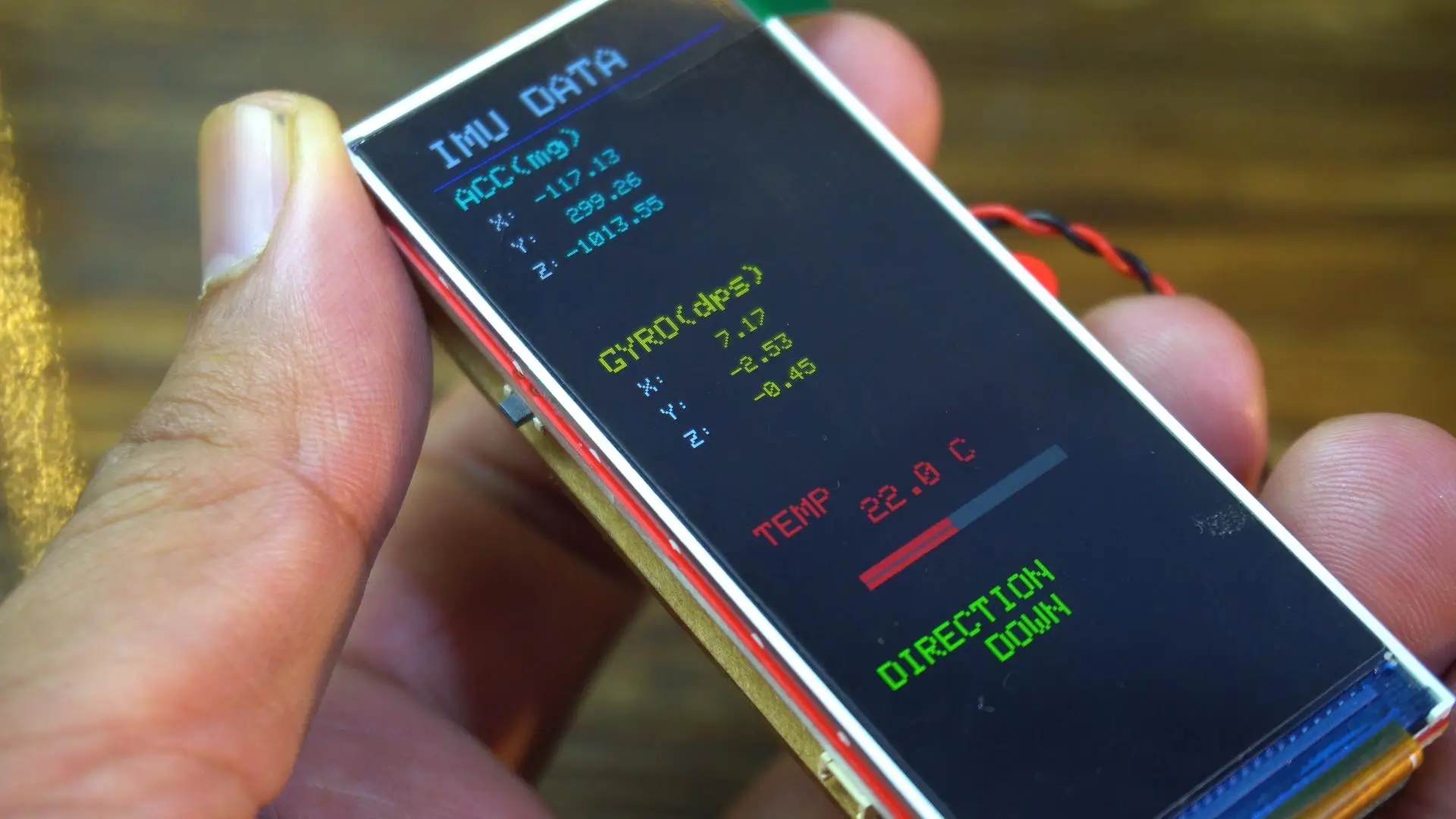
If you try to make changes to this design, it will take a lot of time. While programming, you can’t see the UI visually, so you keep adjusting values, uploading the code, and testing again and again; sometimes for hours; just to get the design right.
PROJECT STRUCTURE
I have already created a basic template folder, which you can download from my Patreon page.
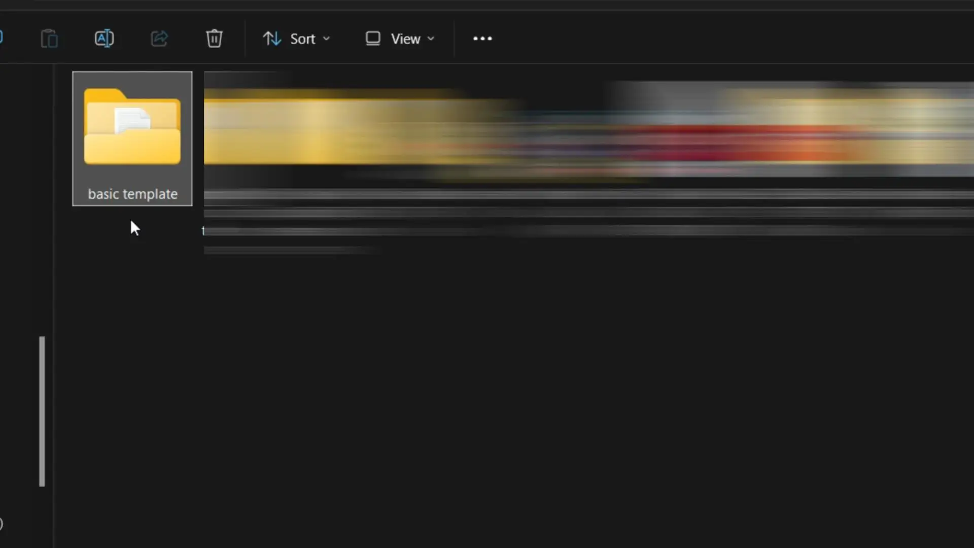
Anyway, after downloading this basic template folder, inside this template folder you will find another folder named first_project. When you open this folder, you will see that all the required files are already generated for you.
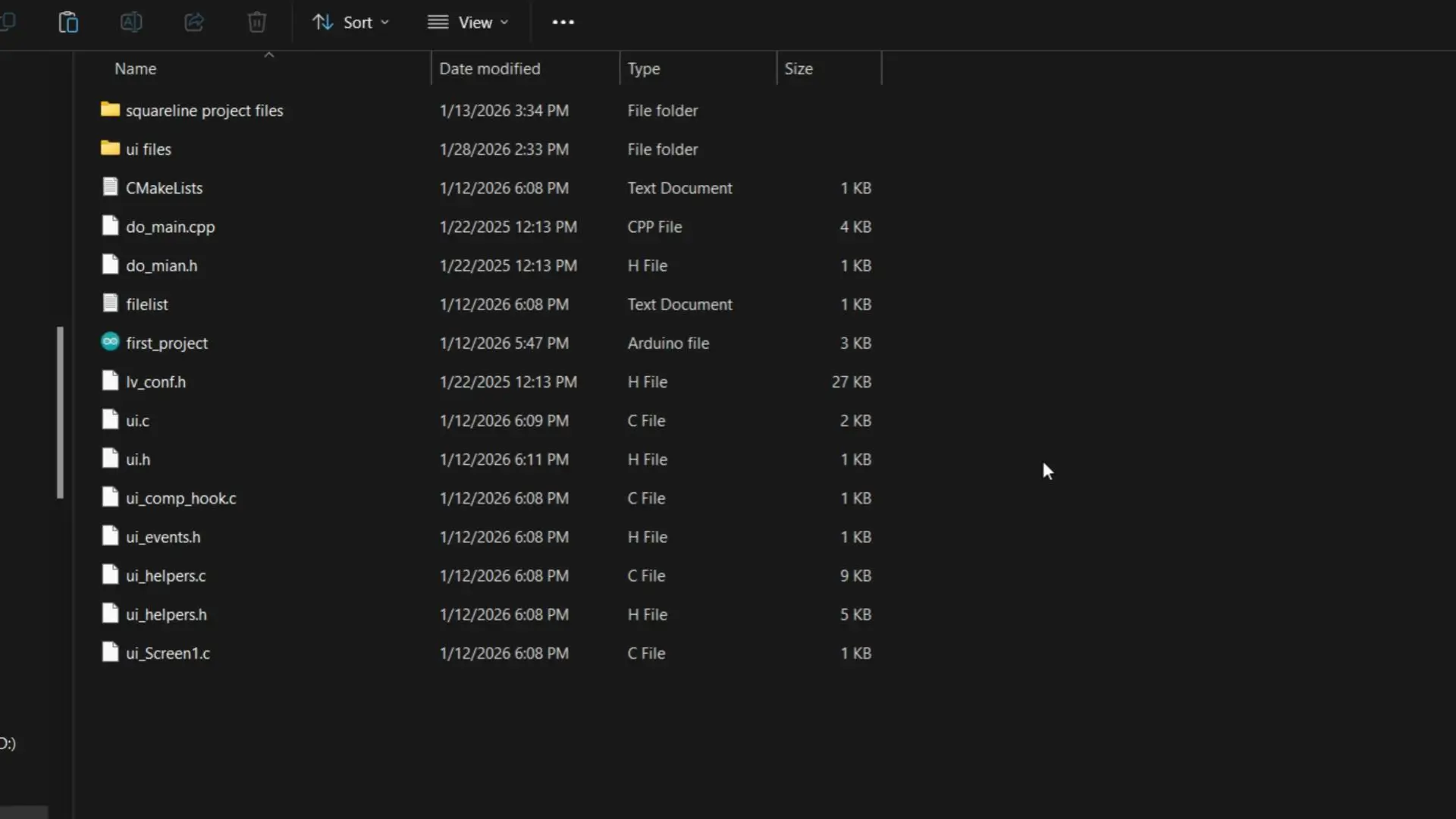
Inside the “ui files” folder, we will place the UI files generated by SquareLine Studio, and in the “squareline project files” folder, we will save the SquareLine Studio project files.
I use the same structure in all my SquareLine-based projects to keep everything clean and organized.
Importing Project in SquareLine Studio:
Now, let’s go ahead and import this project into SquareLine Studio.
SquareLine Studio Setup
I am currently using SquareLine Studio version 1.5.0.
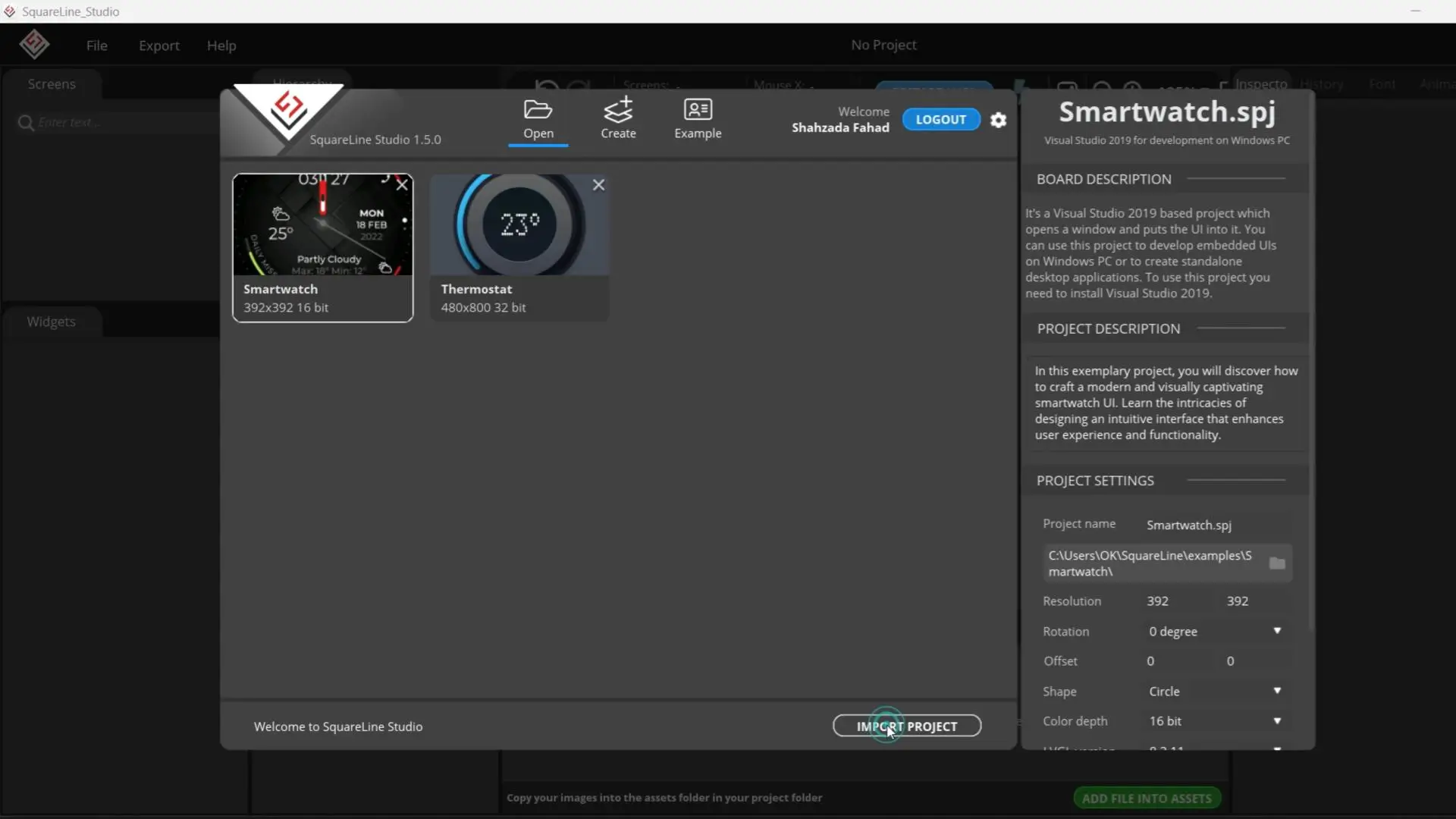
To import the project, click on the Import Project button, browse to the project location, select the project file, and then click Open.
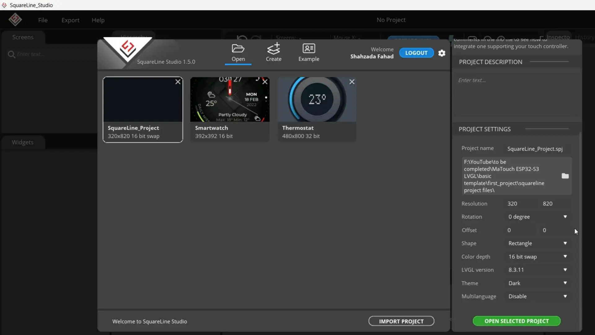
As you can see, the project has now been successfully imported. On the right-hand side, you will find the Project Settings, where you can configure all the important options.
The display resolution is set to 320 by 820, which matches the display we are using. The rotation is set to 0 degrees, and there is no offset applied, so both X and Y offsets are set to zero. The shape is selected as Rectangle.
For color depth, I am using 16-bit swap, which works perfectly with this display and LVGL. The LVGL version is set to 8.3.11, and the theme is Dark, which gives a clean and modern look while designing the UI. I have also kept multilanguage disabled for this project, since it’s not required right now.
These settings are very important, so make sure they match your display and LVGL version before moving forward.
Go to the File menu and then open Project Settings.
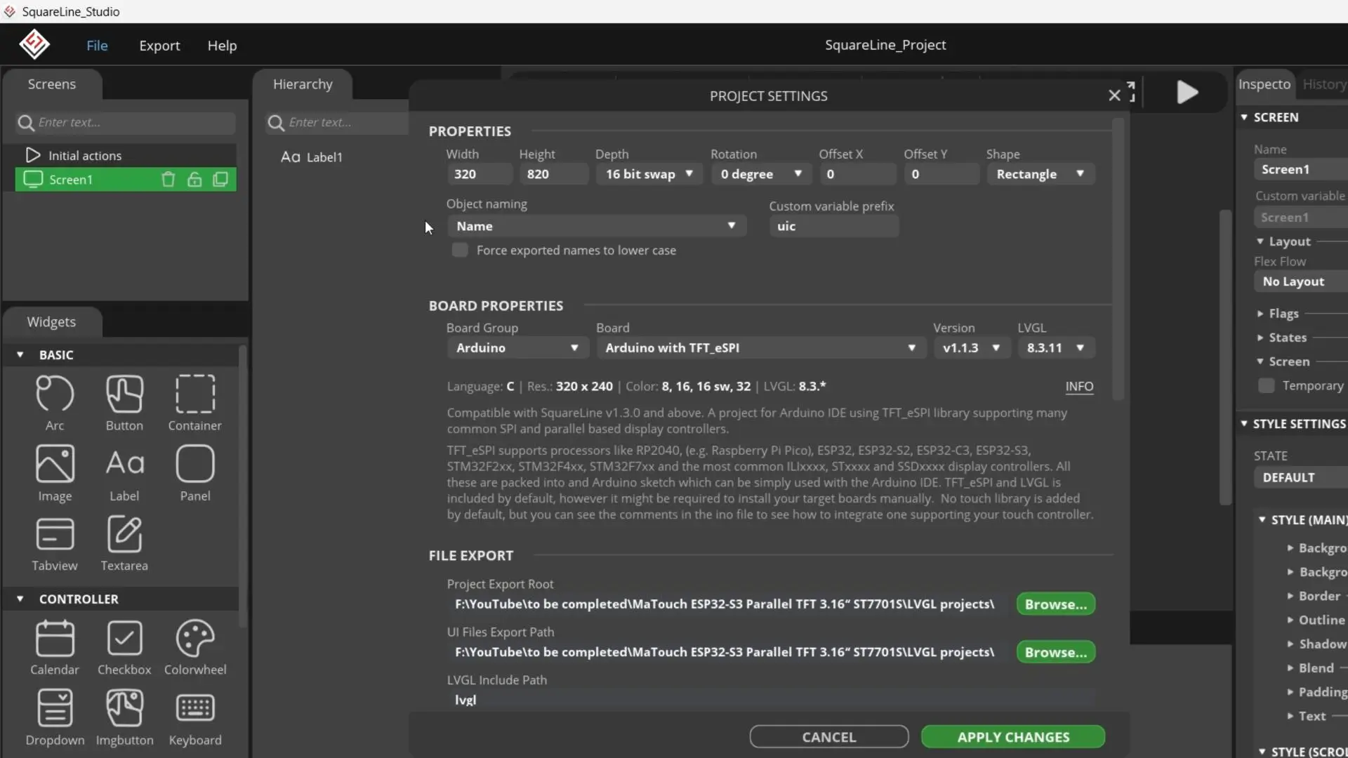
First, make sure the Project Properties are exactly the same as shown on the screen.
Also, confirm that the Board Properties are set correctly and match these settings.
Next, under Fi
After that, set the UI Files Export Path as well.le Export, set the Project Export Root to the folder where you want to save your SquareLine project files.
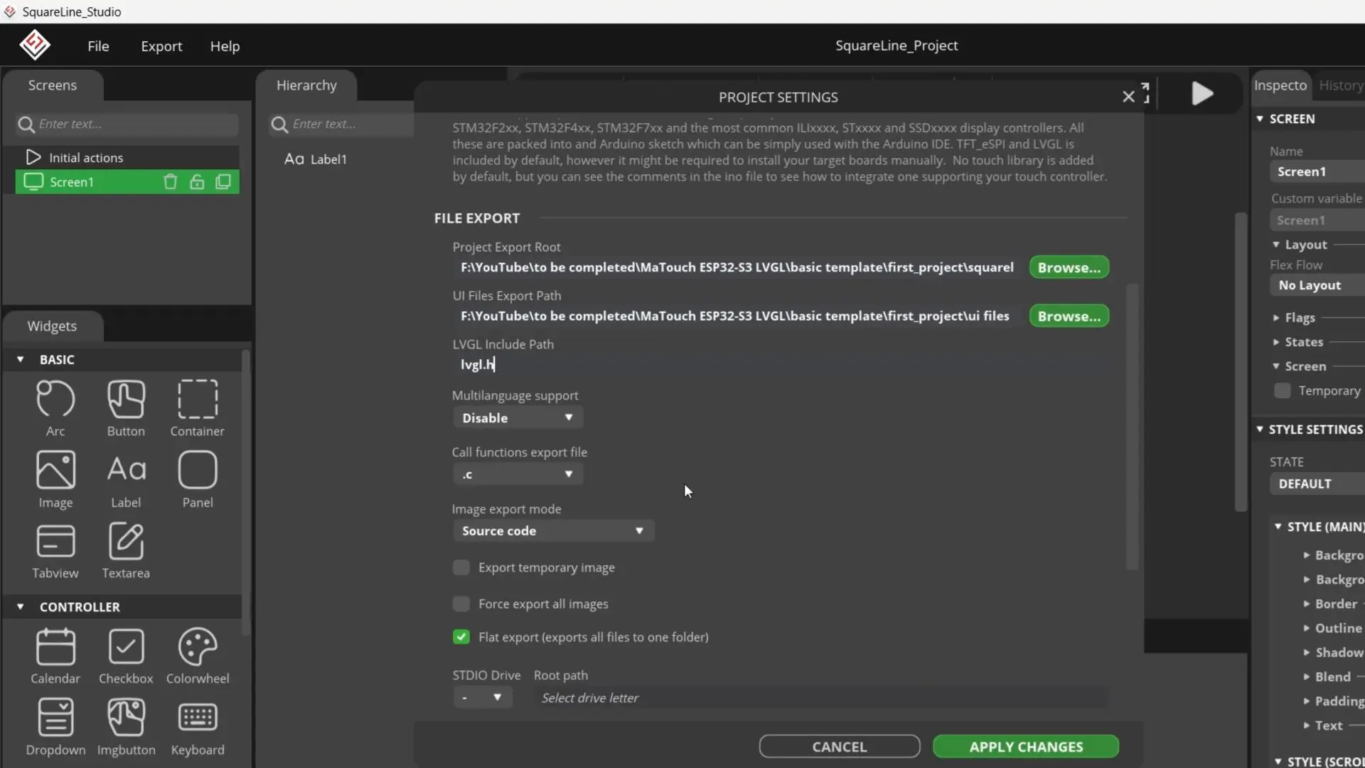
For the LVGL Include Path, simply type lvgl.h.
Now scroll down and make sure Flat Export (export all files into one folder) is checked. Finally, go ahead and click the Apply Changes button to save everything.
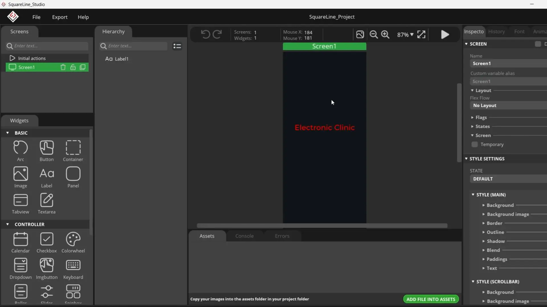
For now, I have only placed “Electronic Clinic” on the display, because at the beginning, your main focus should be on successfully running the project, not on designing a complex UI.
Think of this as your foundation; once it works, you are free to experiment and build much more advanced UIs. you can start adding widgets and move on to building intermediate and advanced-level projects.
For now, let’s continue with this basic text, let’s generate the UI files.
For this go to the Export menu and click on the Export UI Files.
Then go to the ui files folder… copy all the generated files… and paste those files in the same folder where your Arduino main .ino file is located.
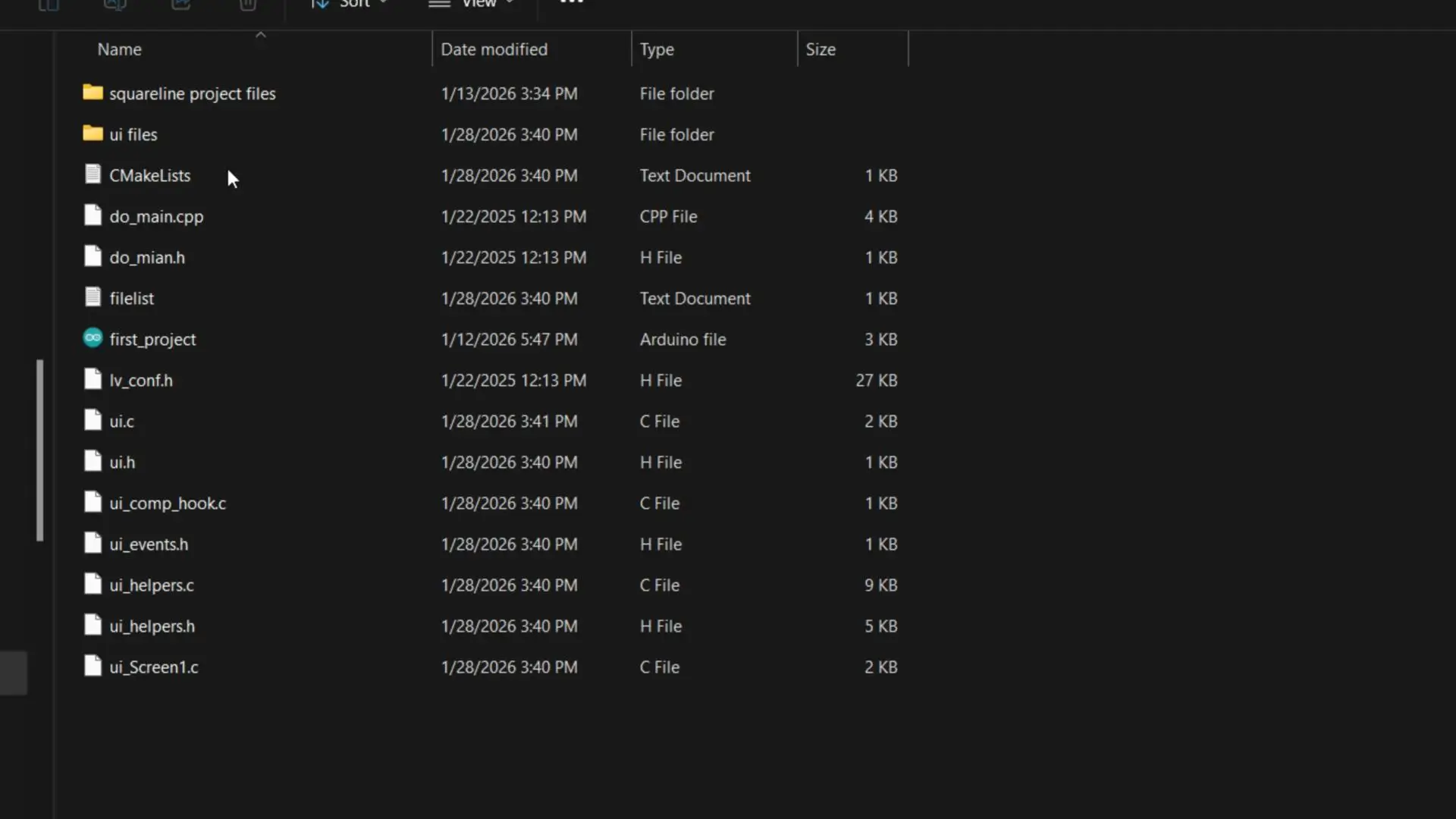
Then open the Arduino main file.
You can see all the generated files are automatically loaded.
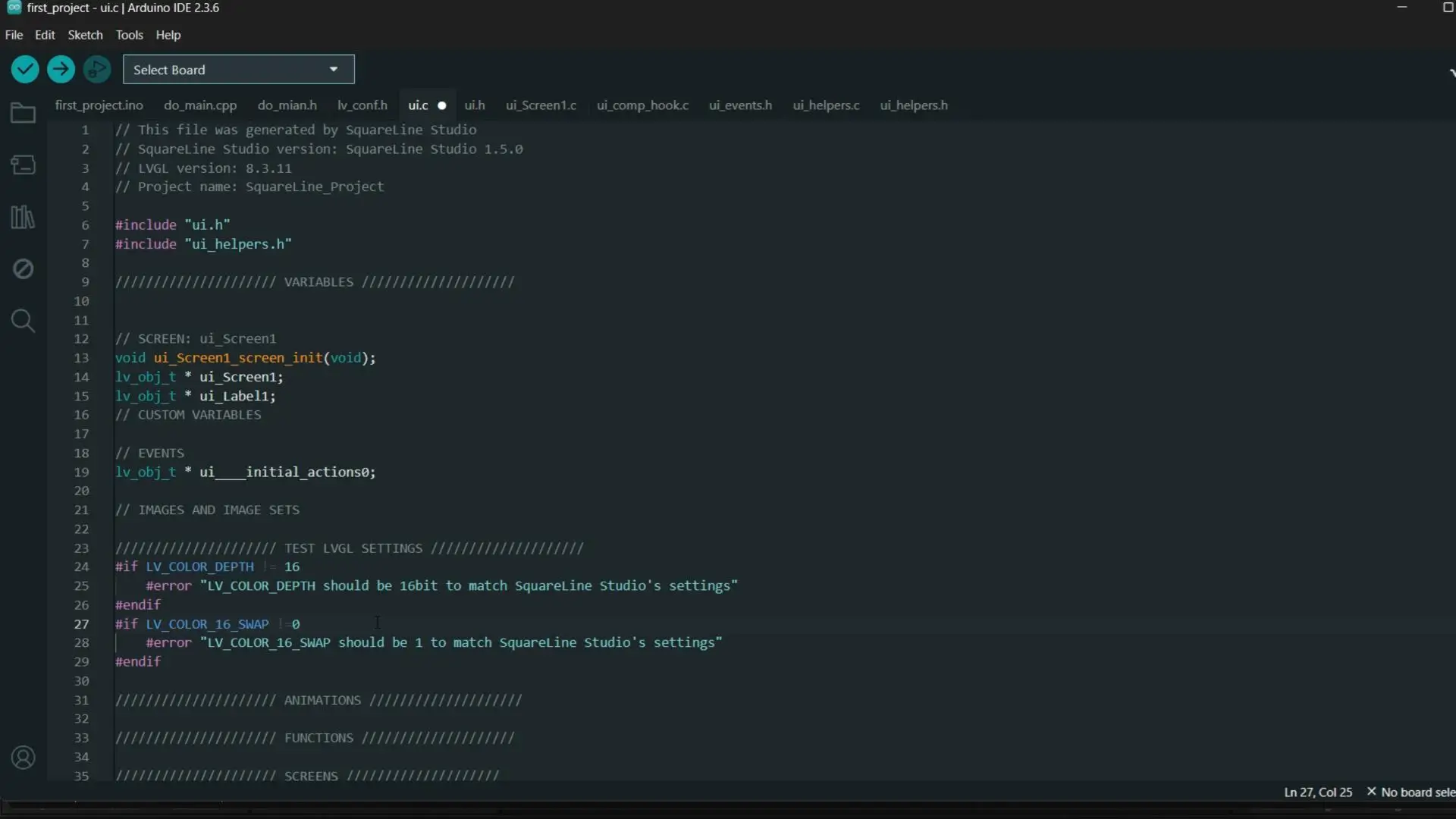
Before you upload the program, go to the ui.c file and change LV_COLOR_16_SWAP from 1 to 0.
LV_COLOR_16_SWAP !=1 into LV_COLOR_16_SWAP !=0
Then go to the ui.h file and make sure its lvgl.h, once all these changes are made. Then you can go ahead and upload the program.
Uploading the Code:
First, go to the Tools menu > Board > ESP32, and select ESP32S3 Dev Module.
Go back to the Tools Menu > Port, and choose the correct communication port.
Again to the tools menu > Flash Size, and select 16MB.
Again go to the Tools menu > Partition Scheme and select 16M Flash
And one last time, go to Tools Menu > PSRAM, and select OPI PSRAM.
Once these settings are done, you can simply click the Upload button.
Note: if you see any error, simply unplug your board, press and hold the Flash button and then plug your board again, make sure you keep the Flash button pressed; upload the code.
Practical Demo:
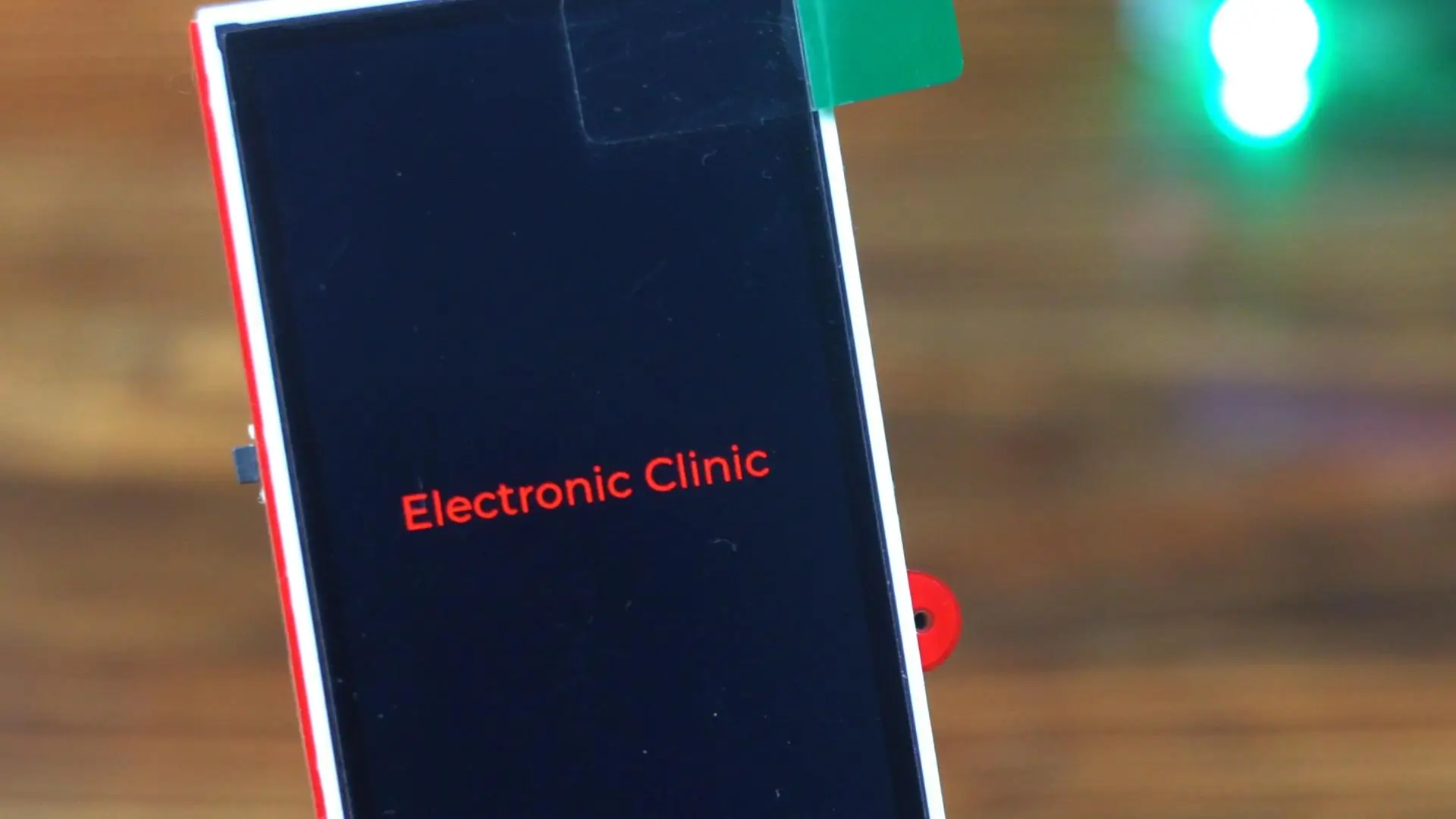
And there it is; Electronic Clinic in red on the display. This is your starting point. Once you reach this stage, you are ready to move on to more advanced UI designs.
Let me show you how quickly we can make changes without writing a single line of code. For this watch the video tutorial.
After changes:
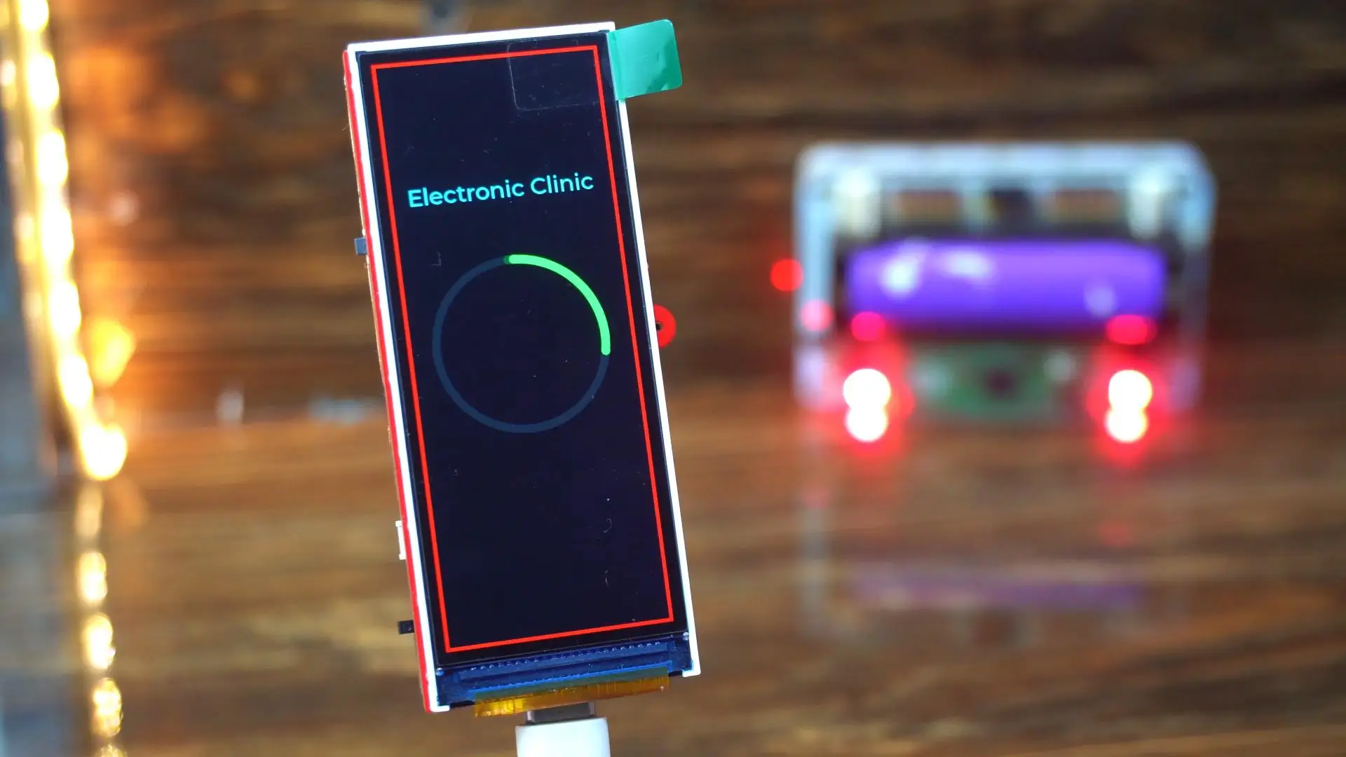
As you can see, it only takes a few seconds to change the entire design. That’s the real power of this workflow. I have really come to like this Makerfabs development kit, and you will be seeing it in many more projects on this website and my YouTube Channel “Electronic Clinic”.
Final Design:
Now, this is my final UI design, and I will quickly walk you through what you are seeing on the screen.
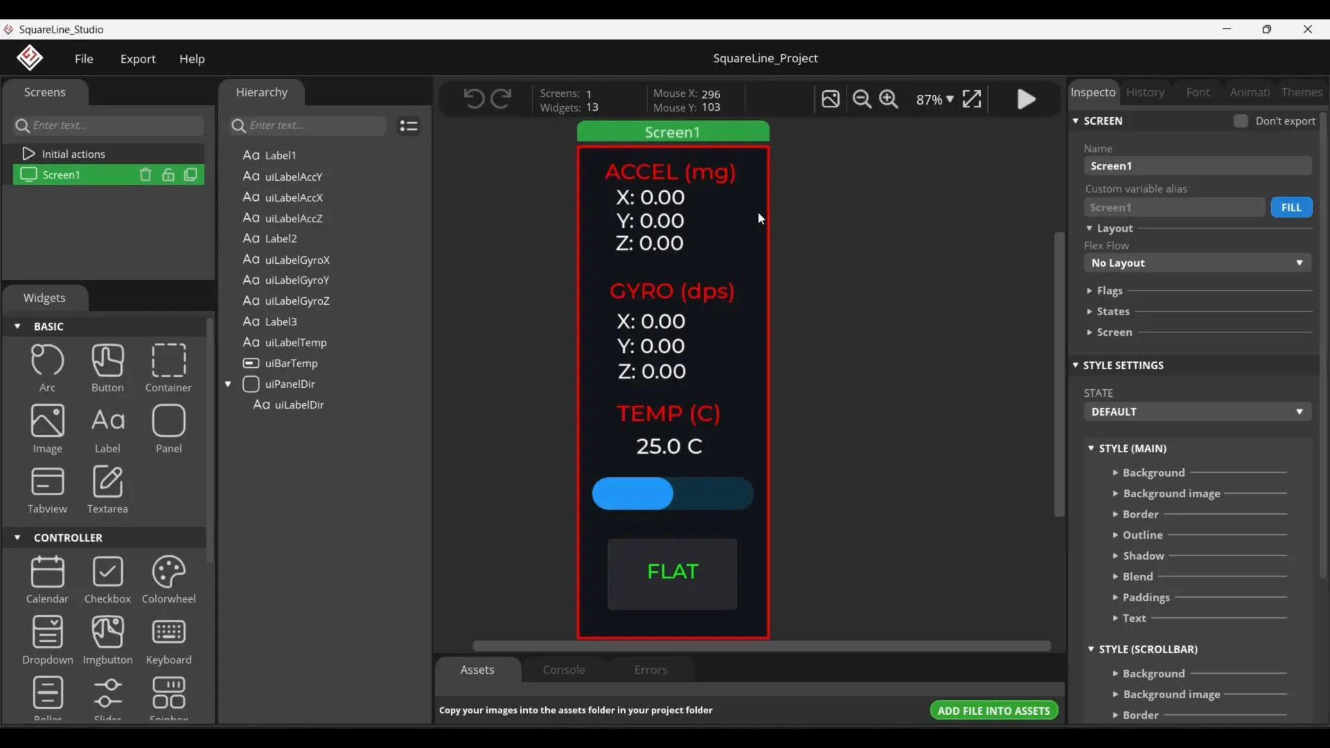
At the top, I have a single screen called Screen1, and on this screen, I am displaying real-time sensor data from the IMU. The first section shows the accelerometer values.
Just below that, I have added the gyroscope section. This gives us real-time rotational information from the IMU.
Next, I am displaying the temperature reading, labeled TEMP (°C). Along with the numeric value, I have also added a temperature bar, which gives a quick visual indication of the temperature level.
At the bottom, there is a direction or orientation indicator, which currently displays FLAT. This label changes based on the orientation of the board, giving instant feedback about its position.
All of these elements are created using labels, panels, and a bar widget, and each widget has its own clearly defined label name making it very easy to locate them later in the Arduino code.
I am not explaining each widget in detail here, because I have already covered every single widget used in this project in my SquareLine Studio getting started articles and vidoes. You will
I have already generated the UI files from SquareLine Studio, and this is the Arduino code that I have already uploaded to the board.
Final UI Code:
|
1 2 3 4 5 6 7 8 9 10 11 12 13 14 15 16 17 18 19 20 21 22 23 24 25 26 27 28 29 30 31 32 33 34 35 36 37 38 39 40 41 42 43 44 45 46 47 48 49 50 51 52 53 54 55 56 57 58 59 60 61 62 63 64 65 66 67 68 69 70 71 72 73 74 75 76 77 78 79 80 81 82 83 84 85 86 87 88 89 90 91 92 93 94 95 96 97 98 99 100 101 102 103 104 105 106 107 108 109 110 111 112 113 114 115 116 117 118 119 120 121 122 123 124 125 126 127 128 129 130 131 132 133 134 135 136 137 138 139 140 141 142 143 144 145 146 147 148 149 150 151 152 153 154 155 156 157 158 159 160 161 162 163 164 165 166 167 168 169 170 171 172 173 174 175 176 177 178 179 180 181 182 183 184 185 186 187 188 189 190 191 192 193 194 195 196 197 198 199 200 201 202 203 204 205 206 207 208 209 210 211 212 213 214 215 216 217 218 219 220 221 222 223 224 225 226 227 228 229 230 231 232 233 234 235 236 237 238 239 240 241 242 243 244 245 246 247 248 249 250 251 252 253 254 255 256 257 258 259 260 261 262 263 264 265 266 267 268 269 270 271 272 273 274 275 276 277 278 279 280 281 282 283 284 285 286 287 288 289 290 291 292 293 294 295 296 297 298 299 300 301 302 303 304 305 306 307 308 309 310 311 312 313 314 315 316 317 318 319 320 321 322 323 324 325 326 327 328 329 330 331 332 333 334 335 336 337 338 339 340 341 342 343 344 345 346 347 348 349 350 351 352 353 354 355 356 357 358 359 360 361 362 363 364 365 366 367 368 369 370 371 372 373 374 375 376 377 378 379 380 381 382 383 384 385 386 387 388 389 390 391 392 393 |
/* SquareLine Studio + Arduino_GFX Template Text: "Electronic Clinic" */ #include <Arduino_GFX_Library.h> #include <lvgl.h> #include <QMI8658.h> #include "ui.h" // Include the UI generated by SquareLine Studio // --- Hardware Pin Definitions --- #define TFT_BLK 46 #define SDA 17 #define SCL 18 // --- Display Setup --- Arduino_DataBus *bus = new Arduino_SWSPI( GFX_NOT_DEFINED /* DC */, 45 /* CS */, 39 /* SCK */, 40 /* MOSI */, GFX_NOT_DEFINED /* MISO */); Arduino_ESP32RGBPanel *rgbpanel = new Arduino_ESP32RGBPanel( 7 /* DE */, 4 /* VSYNC */, 5 /* HSYNC */, 6 /* PCLK */, 12 /* R0 */, 11 /* R1 */, 8 /* R2 */, 16 /* R3 */, 15 /* R4 */, 0 /* G0 */, 14 /* G1 */, 10 /* G2 */, 9 /* G3 */, 3 /* G4 */, 13 /* G5 */, 48 /* B0 */, 47 /* B1 */, 1 /* B2 */, 21 /* B3 */, 41 /* B4 */, 1 /* hsync_polarity */, 10 /* hsync_front_porch */, 8 /* hsync_pulse_width */, 50 /* hsync_back_porch */, 1 /* vsync_polarity */, 10 /* vsync_front_porch */, 8 /* vsync_pulse_width */, 20 /* vsync_back_porch */); Arduino_RGB_Display *gfx = new Arduino_RGB_Display( 320 /* width */, 820 /* height */, rgbpanel, 0 /* rotation */, true /* auto_flush */, bus, GFX_NOT_DEFINED /* RST */, st7701_type9_init_operations, sizeof(st7701_type9_init_operations)); // --- Sensor Instance --- QMI8658 imu; // --- LVGL Buffers --- static lv_disp_draw_buf_t draw_buf; static lv_color_t *buf; // --- Logic Variables --- int Direction = -1; unsigned long lastUpdate = 0; /* Display flushing */ void my_disp_flush(lv_disp_drv_t *disp, const lv_area_t *area, lv_color_t *color_p) { uint32_t w = (area->x2 - area->x1 + 1); uint32_t h = (area->y2 - area->y1 + 1); gfx->draw16bitRGBBitmap(area->x1, area->y1, (uint16_t *)&color_p->full, w, h); lv_disp_flush_ready(disp); } void setup() { Serial.begin(115200); // 1. Hardware Init pinMode(TFT_BLK, OUTPUT); digitalWrite(TFT_BLK, LOW); // 2. Sensor Init if (!imu.begin(SDA, SCL)) { Serial.println("Failed to initialize QMI8658!"); } imu.setAccelRange(QMI8658_ACCEL_RANGE_2G); imu.setAccelODR(QMI8658_ACCEL_ODR_500HZ); imu.setGyroRange(QMI8658_GYRO_RANGE_32DPS); imu.setGyroODR(QMI8658_GYRO_ODR_250HZ); imu.setAccelUnit_mg(true); imu.setGyroUnit_dps(true); imu.enableSensors(QMI8658_ENABLE_ACCEL | QMI8658_ENABLE_GYRO); // 3. Display Init gfx->begin(); gfx->fillScreen(BLACK); // 4. LVGL Init lv_init(); buf = (lv_color_t *)heap_caps_malloc(320 * 100 * sizeof(lv_color_t), MALLOC_CAP_INTERNAL | MALLOC_CAP_8BIT); lv_disp_draw_buf_init(&draw_buf, buf, NULL, 320 * 100); static lv_disp_drv_t disp_drv; lv_disp_drv_init(&disp_drv); disp_drv.hor_res = 320; disp_drv.ver_res = 820; disp_drv.flush_cb = my_disp_flush; disp_drv.draw_buf = &draw_buf; lv_disp_drv_register(&disp_drv); // 5. Init SquareLine UI ui_init(); } void loop() { lv_timer_handler(); if (millis() - lastUpdate > 50) { lastUpdate = millis(); QMI8658_Data data; if (imu.readSensorData(data)) { updateUI(data); } } delay(5); } void updateUI(QMI8658_Data &data) { char strBuf[32]; // --- Update Accelerometer --- snprintf(strBuf, 32, "X: %.2f", data.accelX); lv_label_set_text(ui_uiLabelAccX, strBuf); snprintf(strBuf, 32, "Y: %.2f", data.accelY); lv_label_set_text(ui_uiLabelAccY, strBuf); snprintf(strBuf, 32, "Z: %.2f", data.accelZ); lv_label_set_text(ui_uiLabelAccZ, strBuf); // --- Update Gyro --- snprintf(strBuf, 32, "X: %.2f", data.gyroX); lv_label_set_text(ui_uiLabelGyroX, strBuf); snprintf(strBuf, 32, "Y: %.2f", data.gyroY); lv_label_set_text(ui_uiLabelGyroY, strBuf); snprintf(strBuf, 32, "Z: %.2f", data.gyroZ); lv_label_set_text(ui_uiLabelGyroZ, strBuf); // --- Update Temperature --- snprintf(strBuf, 32, "%.1f C", data.temperature); lv_label_set_text(ui_uiLabelTemp, strBuf); // Update Bar lv_bar_set_value(ui_uiBarTemp, (int)data.temperature, LV_ANIM_OFF); // --- Update Direction Logic --- int newDirection = Direction; if(data.accelX <= -300) newDirection = 1; // Left else if(data.accelX > 300) newDirection = 2; // Right else if(data.accelY <= -300) newDirection = 3; // Up else if(data.accelY > 300) newDirection = 4; // Down else if(data.accelX > -200 && data.accelX < 200 && data.accelY > -200 && data.accelY < 200) newDirection = 0; // Flat if (newDirection != Direction) { Direction = newDirection; updateDirectionUI(Direction); } } void updateDirectionUI(int dir) { // Changing ui_uiLabelDir text and ui_uiPanelDir background color switch(dir) { case 1: lv_label_set_text(ui_uiLabelDir, "LEFT"); lv_obj_set_style_bg_color(ui_uiPanelDir, lv_palette_main(LV_PALETTE_ORANGE), LV_PART_MAIN); break; case 2: lv_label_set_text(ui_uiLabelDir, "RIGHT"); lv_obj_set_style_bg_color(ui_uiPanelDir, lv_palette_main(LV_PALETTE_PURPLE), LV_PART_MAIN); break; case 3: lv_label_set_text(ui_uiLabelDir, "UP"); lv_obj_set_style_bg_color(ui_uiPanelDir, lv_palette_main(LV_PALETTE_BLUE), LV_PART_MAIN); break; case 4: lv_label_set_text(ui_uiLabelDir, "DOWN"); lv_obj_set_style_bg_color(ui_uiPanelDir, lv_palette_main(LV_PALETTE_TEAL), LV_PART_MAIN); break; case 0: default: lv_label_set_text(ui_uiLabelDir, "FLAT"); // Set to default greyish color lv_obj_set_style_bg_color(ui_uiPanelDir, lv_color_make(50, 50, 50), LV_PART_MAIN); break; } } |
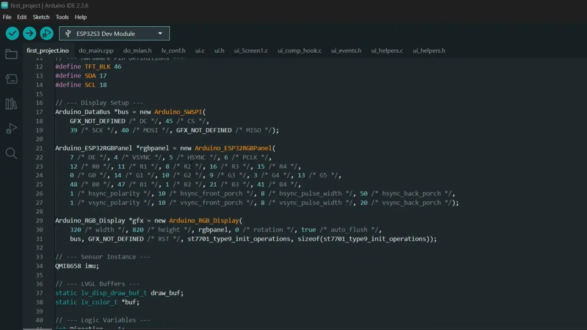
You can download this entire project folder from my patreon page. It includes all the UI files. So now that everything is ready, let’s go ahead and see this project in action.
Practical Demo:
Alright, now I am holding the board in my hand, and you can see the UI is running live on the display.
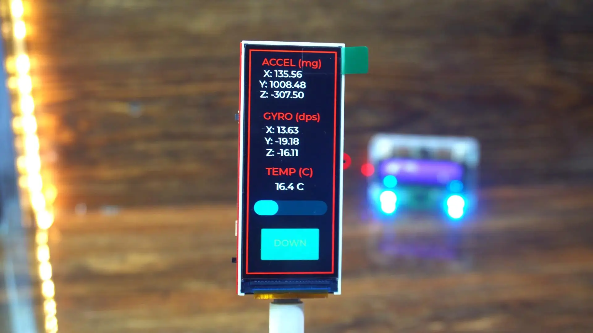
All the values you are seeing are updating in real time.
As I gently move the board, notice how smoothly and quickly the accelerometer and gyroscope values change. There’s no lag, no delay; everything feels very responsive. This is where the ESP32-S3 really shines. Compared to Arduino, the processing is much faster, and handling graphics, sensors, and UI at the same time feels effortless.
Now, let me tilt the board towards the left…
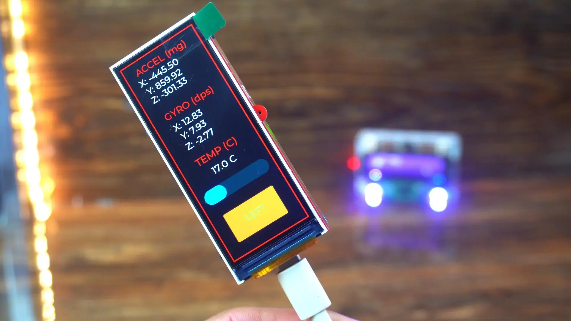
You can see the values changing instantly, and the direction updates accordingly.
If I tilt it towards the right, the readings update just as smoothly.
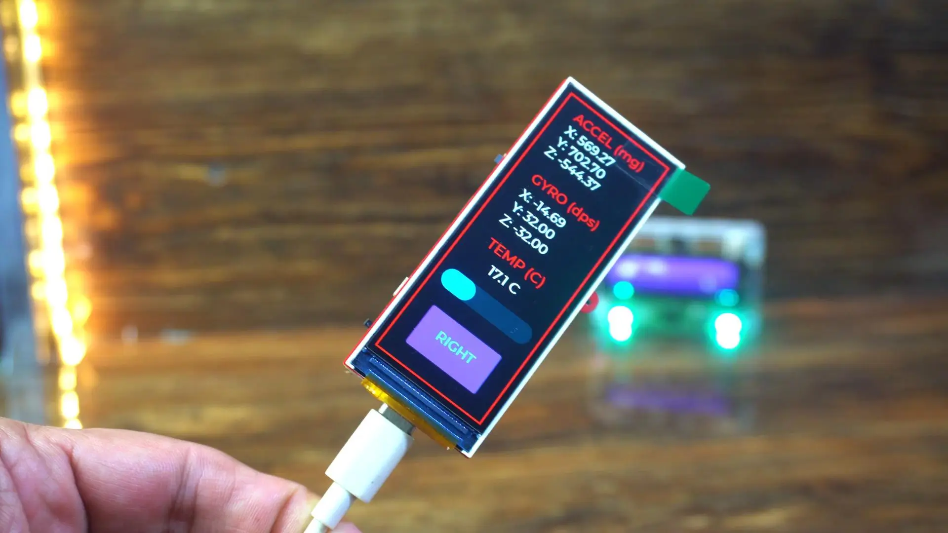
There’s no freezing, no stuttering; the UI keeps running perfectly while the sensor data is being processed in the background.
And now, I will place the board flat on the table…
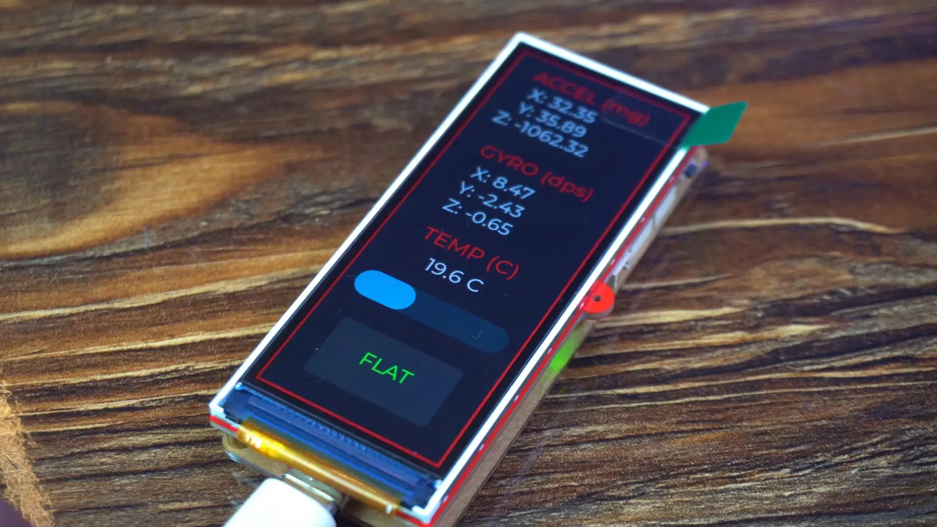
As you can see, the direction changes to FLAT. This confirms that both the IMU data and the logic behind it are working correctly.
What I really like here is how fluid the entire experience feels. The UI updates, the sensor readings, and the orientation changes all happen smoothly, without any visible delay.
Doing something like this on a traditional Arduino setup would be much more difficult; especially with a graphical interface and multiple sensors running at the same time.
This is exactly why the ESP32-S3 is such a powerful choice. You get fast processing, smooth graphics, and real-time sensor handling; all on a single, compact board.
And this is just the beginning. Once you have this foundation working, you can easily expand it into more advanced, interactive, and professional-level projects.
So, that’s all for now.
Support me on Patreon:
If you enjoy my work and find these projects helpful, please consider supporting me on Patreon. With just $1, you can get access to all project source codes, schematics, and extra resources that I share with my supporters. Your support helps me continue creating new electronics tutorials, experiments, and open projects for the community. Thank you so much for being part of this journey and for supporting my work!
Watch Video Tutorial:
Discover more from Electronic Clinic
Subscribe to get the latest posts sent to your email.