I Built a Solar-Powered Water Tank Level Sensor
Last Updated on September 8, 2026 by Engr. Shahzada Fahad
Table of Contents
Description:
Today, we are going to make the most versatile solar-powered water tank monitoring system.
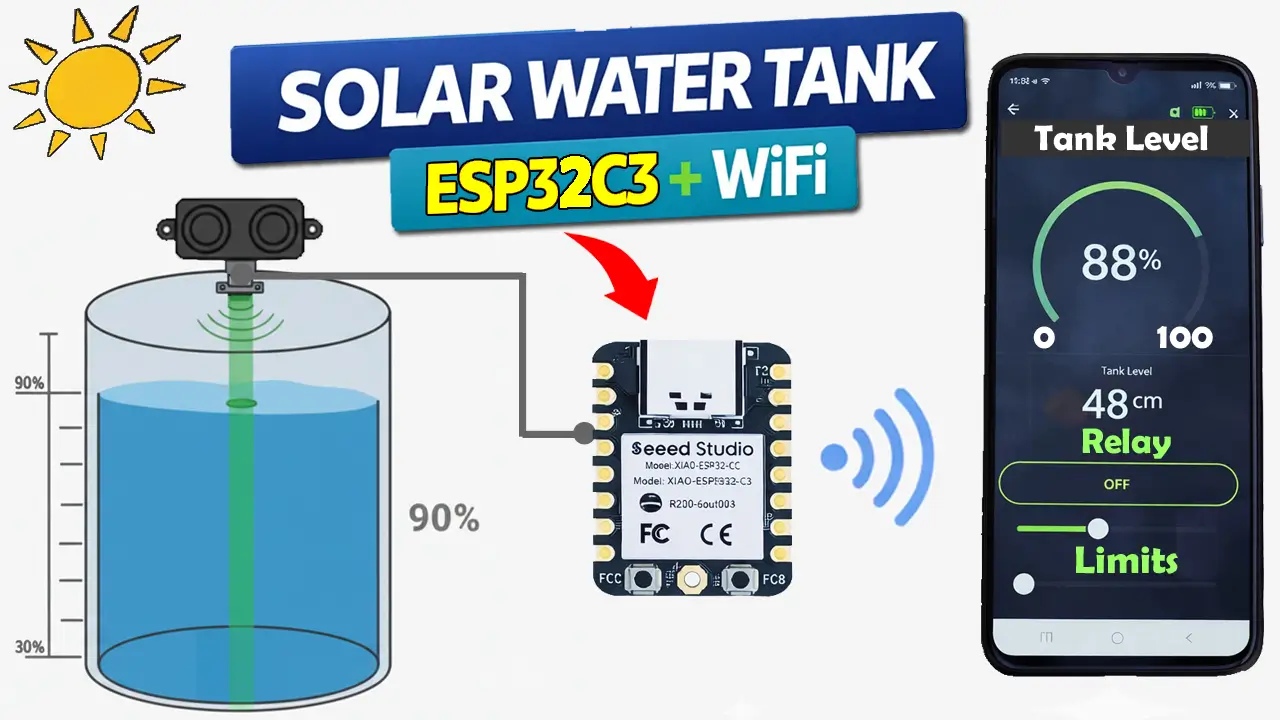
I said versatile because we can define the water tank lower and upper limits in real time through a mobile application created using Blynk IoT. Based on these limits, the water pump will automatically start and stop.
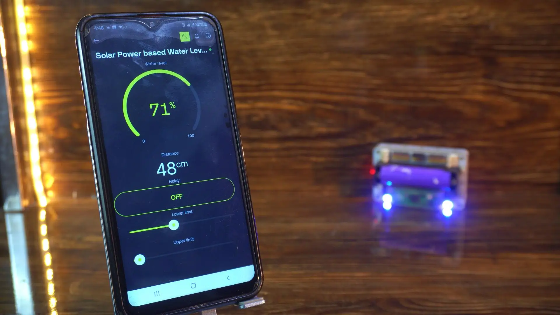
There are hundreds of thousands of different types and sizes of water tanks, so that’s why I added the lower and upper limits, which are completely adjustable during runtime. You set these limits once unless you want to change them again, because these values are stored in the EEPROM. So, it doesn’t matter if the controller is reset or powered off; these values won’t go anywhere. If these values were reset due to a power failure or accidental reset, then this entire system would be useless.
You can not only see the percentage and actual distance in cm in the application, but also on the OLED display module, which is optional.
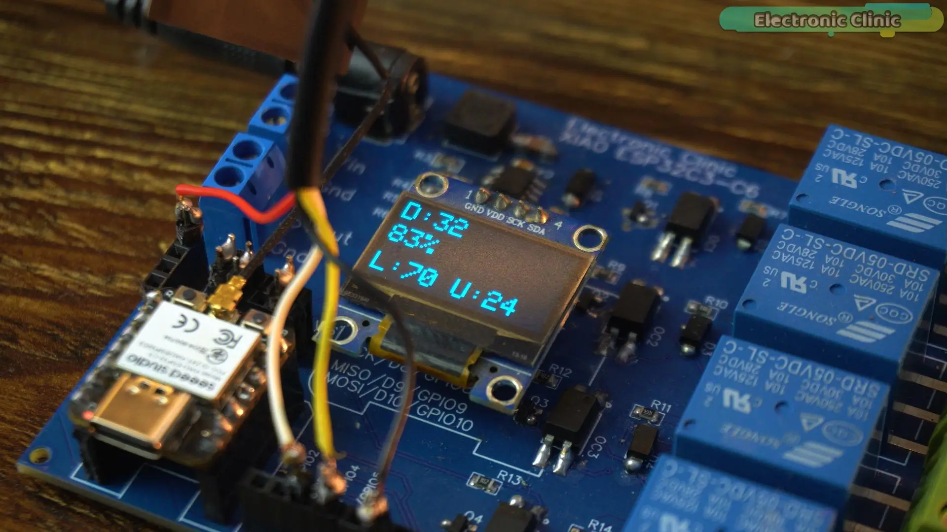
Along with the distance and percentage values, you can also see the lower and upper limits. If I am going to change any of these values, they are quickly updated on the OLED display module, and the updated values are also stored in the EEPROM.
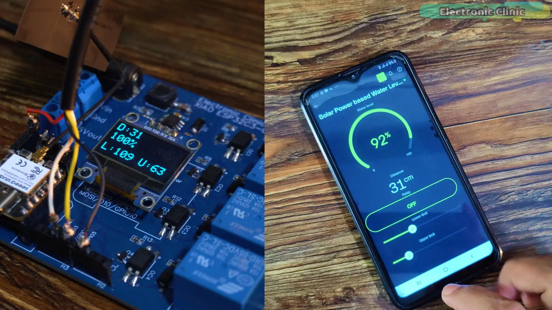
Let me reset the controller so that you can see these values are not lost.
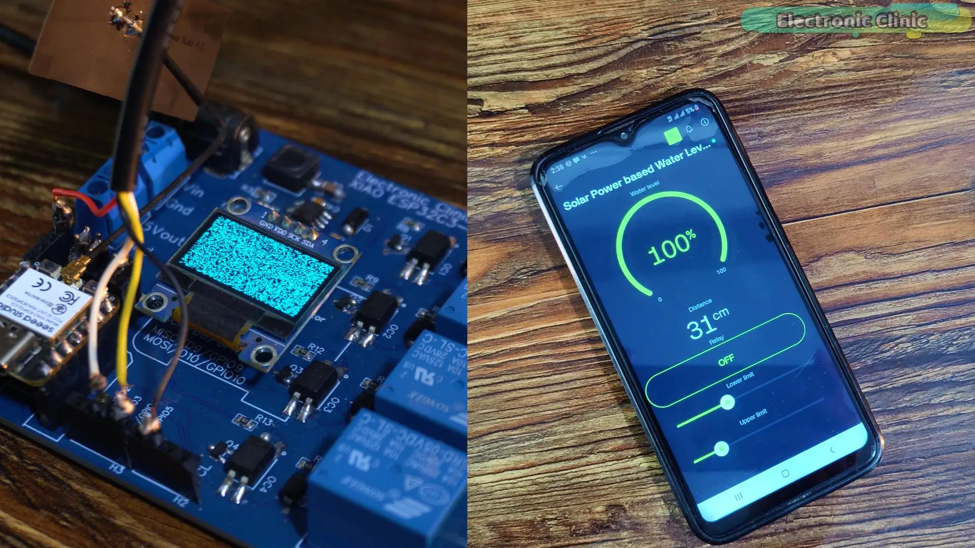
In the image above, you can see, I restarted the controller.
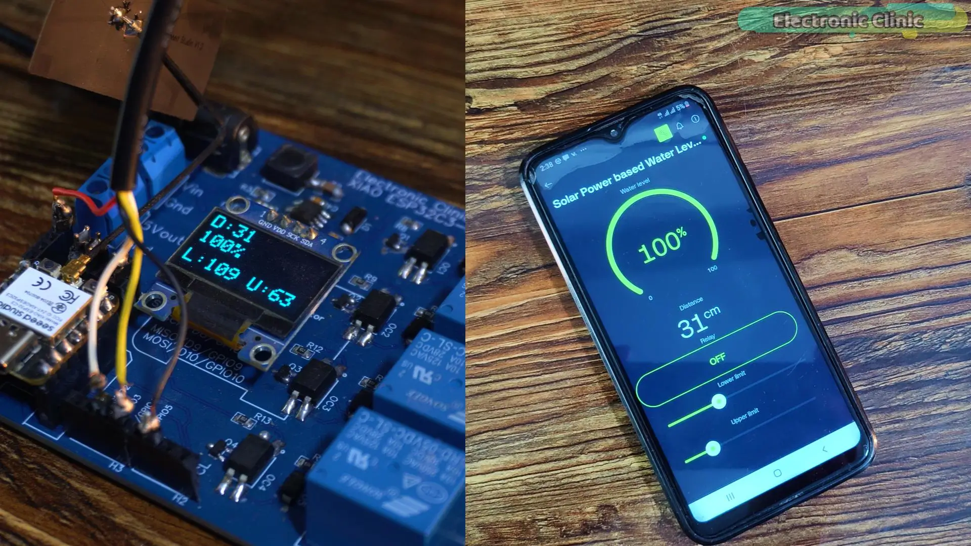
Great! You can see the lower and upper limits are still there.
In the application, you can also see a button, which you can use to manually control the water pump.
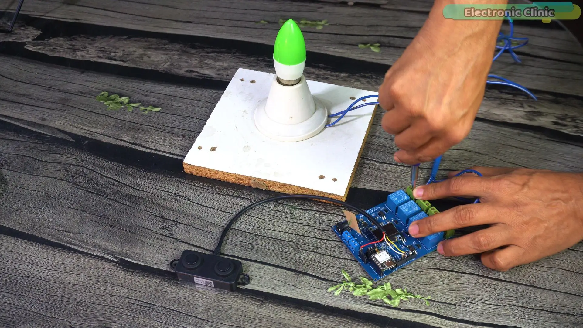
Let me quickly connect this bulb to the relay so that you can practically see what happens, because during the practical demo, you won’t be able to see how the water pump turns ON and OFF. So, right now, you can think of this bulb as the water pump.
Make sure to wear protective gloves while performing such high-voltage experiments, and don’t touch the relay contacts. Because safety first.
Before I show you this entire system in action, first let me tell you about the hardware. What makes this project unique is the hardware selection.
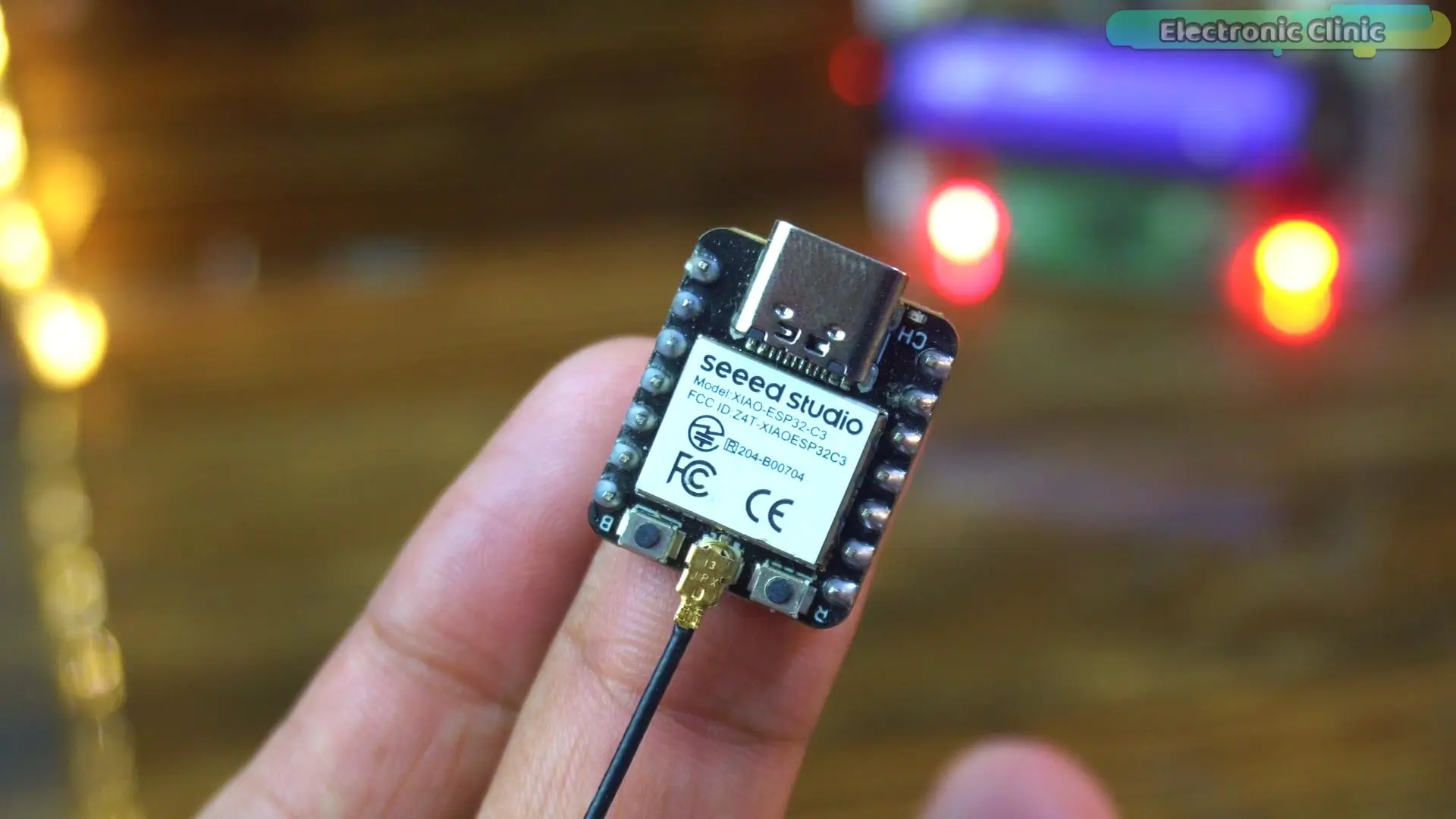
For this project, I selected the Xiao ESP32C3. Well, you can use any ESP32 variant, but the reason I selected the Xiao ESP32C3 is that in the Xiao series, you also get the Xiao ESP32C5 and Xiao ESP32C6.
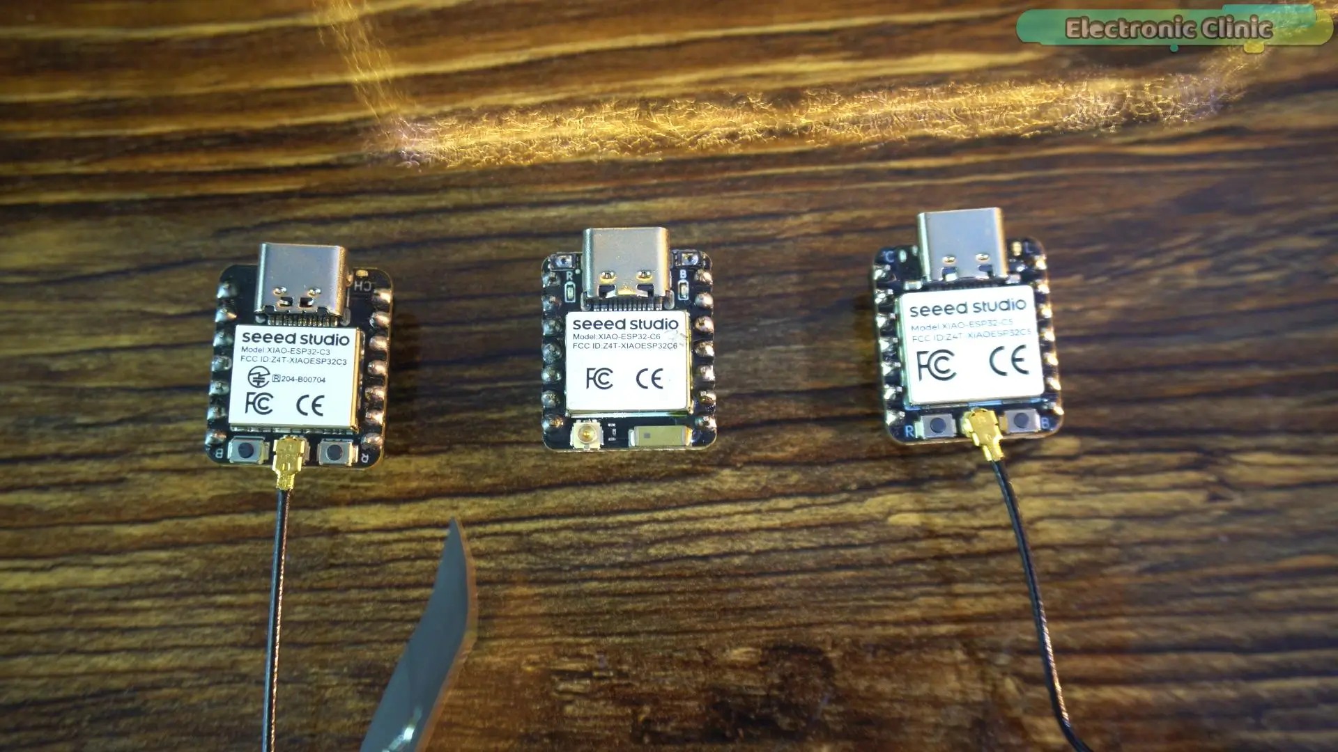
So, later, if you decide to switch to WiFi 6, you can simply use the ESP32C5, and if you don’t want to use this flexible PCB antenna, then you can switch to the Xiao ESP32C6. And let me tell you, since all these boards share the exact same pin layout, there is no need to make any changes on the hardware side. I have already demonstrated this in my previous video. I will add a link in the description below.
If you ask about my personal recommendation, I would select the Xiao ESP32C3 because its Bluetooth range, due to the flexible PCB antenna, is great. I have an article on its range test.
For water level monitoring, I am using the most accurate, highly reliable, and completely waterproof ultrasonic sensor, the “A02YYUW.”
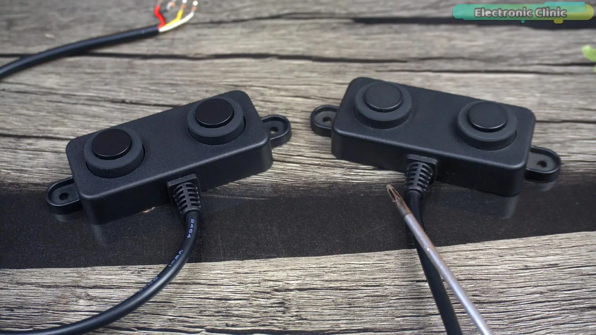
There are two versions of the same ultrasonic sensor: one is UART, and the other is PWM. The one I am using is the UART version. Its measurement range is from 3 cm to 450 cm. And when it comes to the voltage, it is compatible with 3.3V and 5V controller boards. It is a little bit more expensive than the HC-SR04 and the JSN SR04T ultrasonic sensors. Personally, I have used all these sensors, but my recommendation is the A02YYUW waterproof ultrasonic sensor.
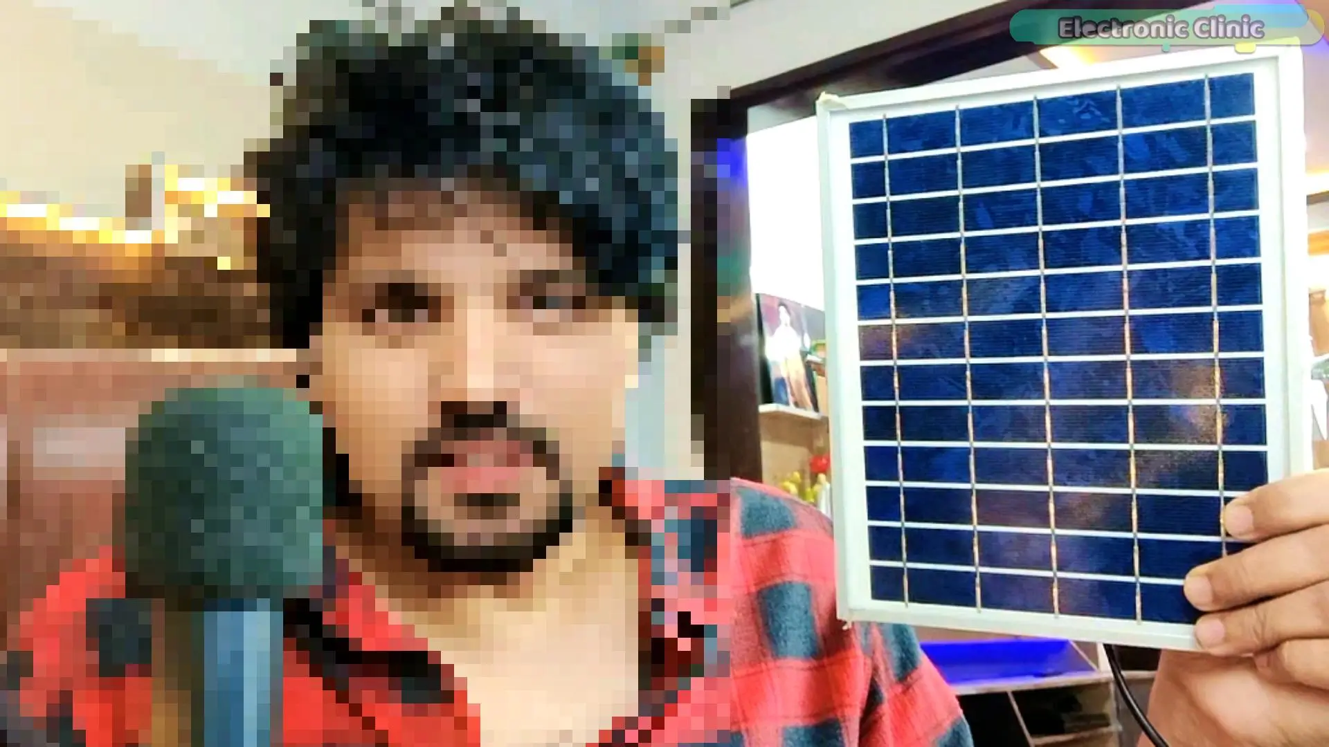
You will also need a solar panel, a bigger one or a mini solar panel like this. You don’t need to worry about the voltage because the 5V 3A power supply on my designed board can take input voltages up to 28 volts.
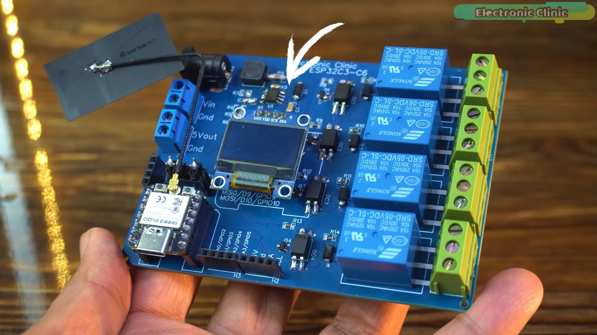
And the battery charging and management are done by the Xiao ESP32C3. So, that’s why I didn’t add any battery charging circuit to this board.
For how to make this board, I have also made a dedicated video about it, and you can download the original schematic, PCB design files, BOM, and all the other resources from my Patreon page.
Solar Powered Water Tank Level Sensor Wiring:
The ultrasonic sensor red and black wires are connected to the 3.3V and GND of the Xiao ESP32C3, and the TX and RX wires are connected to the D2 and D3 pins on the Xiao ESP32C3.
A 5-volt SPDT-type relay is connected to the D0 pin.
The SSD1306 OLED display module voltage and ground pins are connected to 3.3V and GND, and the SDA and SCL pins are connected to D4 and D5.
Circuit diagram:
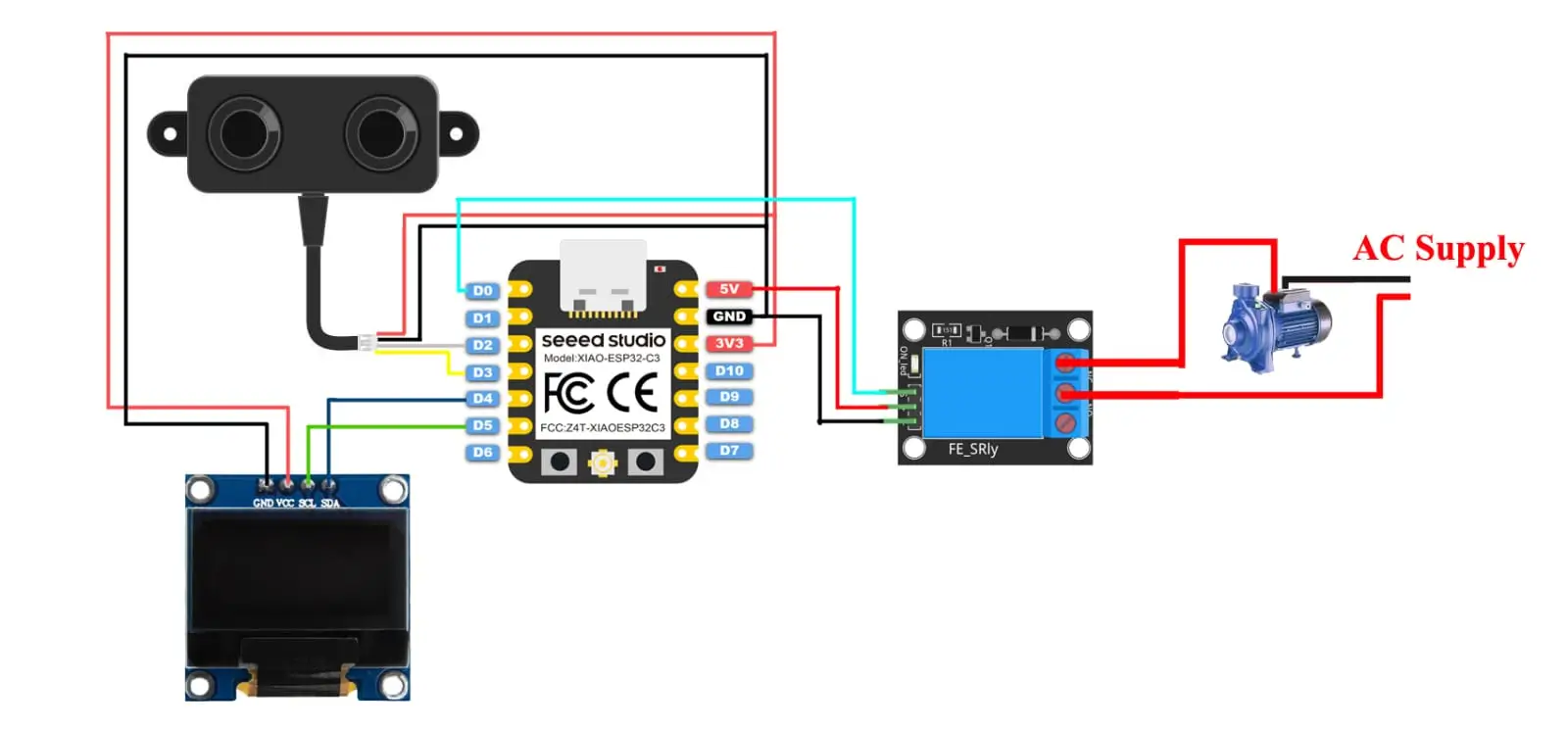
Since we are using the Blynk application, we can monitor the water level and adjust the lower and upper limits from anywhere in the world.
A quick demo before the practical implementation.
I have powered up the project using a 12V adapter. Later, we will use a solar panel.
The Ultrasonic Sensor is in its place, the ESP32 and Blynk application are connected to the WiFi.
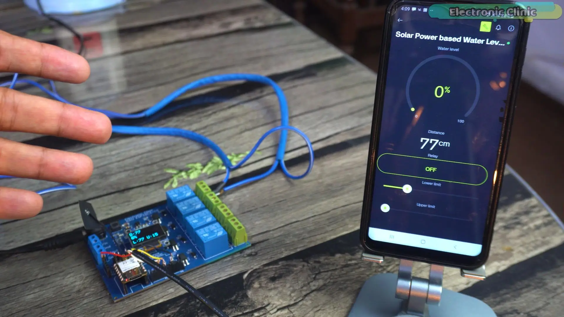
Let me also tell you, there is no need to connect to the same WiFi, you can use a different WiFi network or a mobile hotspot on the mobile side. It is an IoT based Water Level monitoring system, you can connect to your ESP32 board from any part of the world.
The lower and upper limits are already set.
Now watch as I move this tablet.
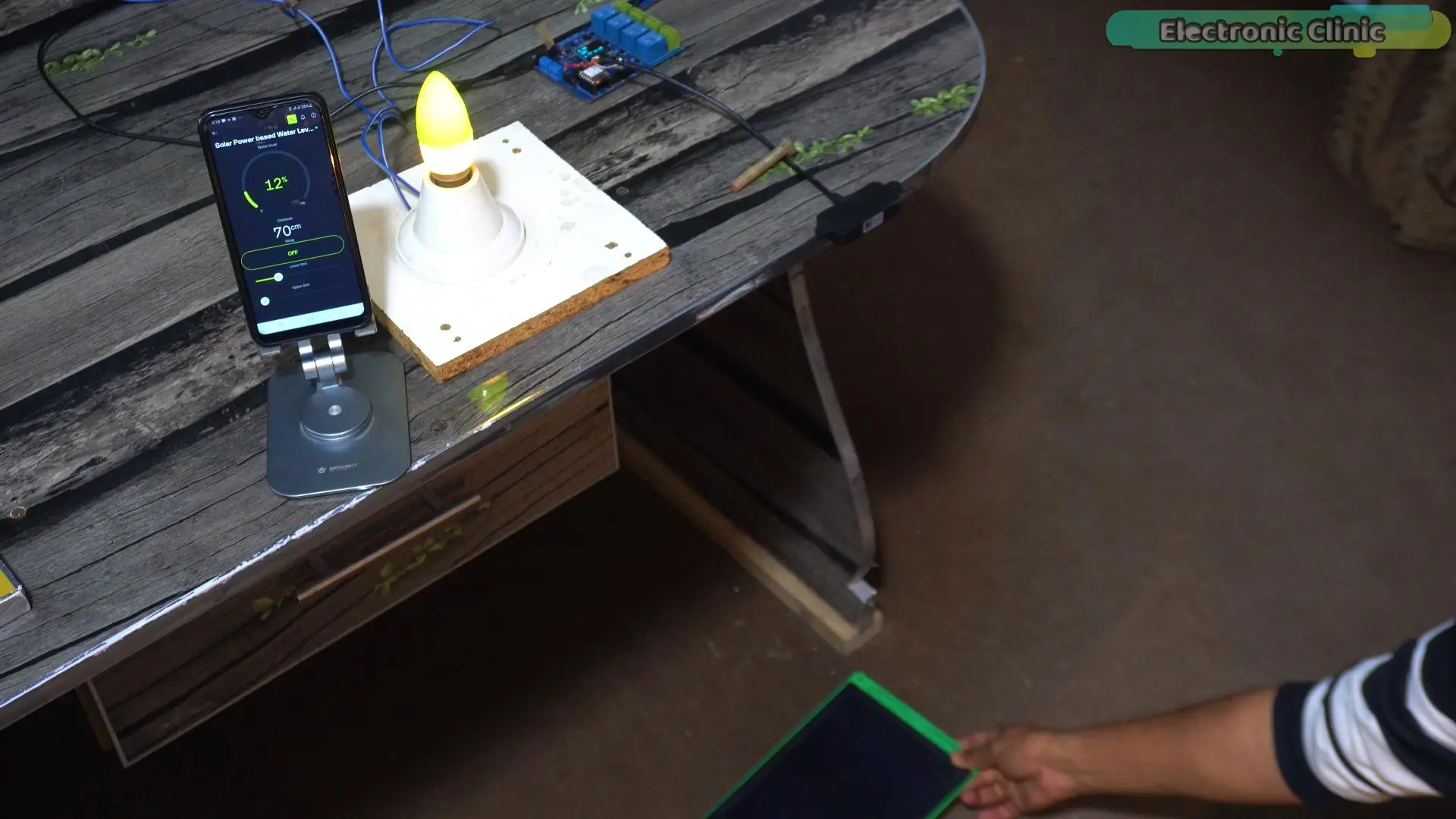
Think of it as the water level. The bulb is ON because the water level is below 20%. It will remain ON until the water level increases above 85%.
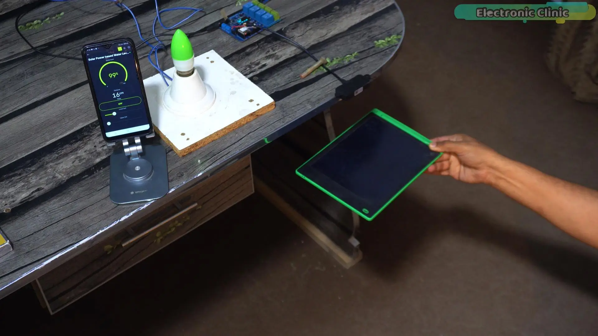
Now, the water pump will remain off until the water level decreases below 20%. As you can see, the entire system is working as expected. And one more thing:
if I don’t want the water tank to fill completely, I can use the relay button to turn OFF the water pump, or if I want, I can use it to turn ON the water pump.
Now, let’s connect the solar panel.
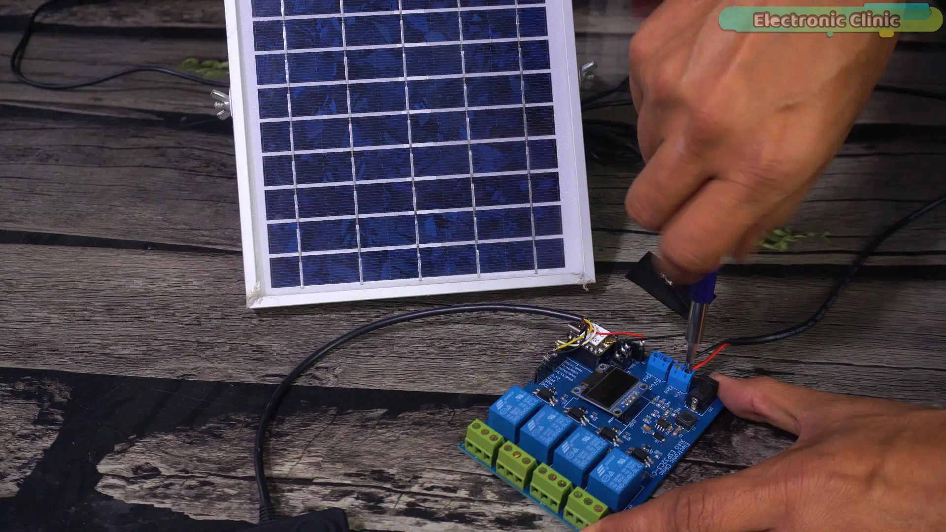
I am going to connect the red wire to VIN and the black wire to GND.
Now, before the final demonstration, let me show you how to create your Blynk application.
Blynk Web Dashboard Setup:
Watch Video Tutorial on my YouTube Channel Electronic Clinic; link is given at the end of this article.
If this is your first time using the Blynk IoT Cloud and ESP32 WiFi + Bluetooth; I highly recommend reading my getting started article on the ESP32 and New Blynk.
Solar Powered Water Tank Monitoring Code:
|
1 2 3 4 5 6 7 8 9 10 11 12 13 14 15 16 17 18 19 20 21 22 23 24 25 26 27 28 29 30 31 32 33 34 35 36 37 38 39 40 41 42 43 44 45 46 47 48 49 50 51 52 53 54 55 56 57 58 59 60 61 62 63 64 65 66 67 68 69 70 71 72 73 74 75 76 77 78 79 80 81 82 83 84 85 86 87 88 89 90 91 92 93 94 95 96 97 98 99 100 101 102 103 104 105 106 107 108 109 110 111 112 113 114 115 116 117 118 119 120 121 122 123 124 125 126 127 128 129 130 131 132 133 134 135 136 137 138 139 140 141 142 143 144 145 146 147 148 149 150 151 152 153 154 155 156 157 158 159 160 161 162 163 164 165 166 167 168 169 170 171 172 173 174 175 176 177 178 179 180 181 182 183 |
#define BLYNK_TEMPLATE_ID "TMPL6Tk_ZjKnm" #define BLYNK_TEMPLATE_NAME "Solar Power based Water Level Monitoring" #define BLYNK_AUTH_TOKEN "VB8IusyVbwJydqseZKaz-sjPocRbyGS4" #include <WiFi.h> #include <WiFiClient.h> #include <BlynkSimpleEsp32.h> #include <EEPROM.h> #include <Wire.h> #include <Adafruit_GFX.h> #include <Adafruit_SSD1306.h> #include <HardwareSerial.h> HardwareSerial Ultrasonic_Sensor(1); // // Define connections to sensor int pinRX = D2; // white wire int pinTX = D3; // yellow wire char auth[] = BLYNK_AUTH_TOKEN; // Your WiFi credentials. // Set password to "" for open networks. char ssid[] = "AndroidAP3DEC"; char pass[] = "11122233"; #define SCREEN_WIDTH 128 // OLED display width, in pixels #define SCREEN_HEIGHT 64 // OLED display height, in pixels // Declaration for an SSD1306 display connected to I2C (SDA, SCL pins) #define OLED_RESET -1 // Reset pin # (or -1 if sharing Arduino reset pin) Adafruit_SSD1306 display(SCREEN_WIDTH, SCREEN_HEIGHT, &Wire, OLED_RESET); unsigned char data_buffer[4] = {0}; int distance; int waterLevelPer; // Variable to hold checksum unsigned char CS; int Relay = D0; int Relay_Status = 0; int Percentage = 0; int previousDistance; unsigned long distanceChangeTime; BlynkTimer timer; int lowerlevel; int upperlevel; void setup() { Serial.begin(115200); // Initialize the serial monitor Ultrasonic_Sensor.begin(9600, SERIAL_8N1, pinRX, pinTX); // Initialize the hardware serial pinMode(Relay,OUTPUT); Blynk.begin(auth, ssid, pass); display.begin(SSD1306_SWITCHCAPVCC, 0x3C); delay(2000); display.clearDisplay(); display.setTextColor(WHITE); EEPROM.begin(512); upperlevel = EEPROM.read(0); lowerlevel = EEPROM.read(1); timer.setInterval(1000L, displayvalues); } void loop() { Blynk.run(); timer.run(); // Initiates SimpleTimer A02YYUW_Sensor(); } void A02YYUW_Sensor() { if (Ultrasonic_Sensor.available() > 0) { delay(4); // Check for packet header character 0xff if (Ultrasonic_Sensor.read() == 0xff) { // Insert header into array data_buffer[0] = 0xff; // Read remaining 3 characters of data and insert into array for (int i = 1; i < 4; i++) { data_buffer[i] = Ultrasonic_Sensor.read(); } //Compute checksum CS = data_buffer[0] + data_buffer[1] + data_buffer[2]; // If checksum is valid compose distance from data if (data_buffer[3] == CS) { distance = (data_buffer[1] << 8) + data_buffer[2]; // Print to serial monitor distance= distance / 10; // cm } } } Serial.print("distance: "); Serial.print(distance); Serial.println(" cm"); } void displayvalues() { waterLevelPer = map(distance, upperlevel, lowerlevel, 100, 0); // display on Oled display if(waterLevelPer<0) { waterLevelPer=0; } if(waterLevelPer>100) { waterLevelPer=100; } if (waterLevelPer <= 20) { digitalWrite(Relay, HIGH); delay(10); } if (waterLevelPer >= 85) { digitalWrite(Relay, LOW); delay(10); } // Oled display display.clearDisplay(); display.setCursor(0,0); display.setTextSize(2); display.setTextColor(WHITE); display.print(String("D:")+distance); display.setCursor(0,20); display.setTextSize(2); display.print(String(waterLevelPer)+"%"); display.setTextSize(2); display.setCursor(0,20); display.setCursor(0,45); display.setTextSize(2); display.print("L:"+String(lowerlevel)+" U:"+String(upperlevel)); display.display(); Blynk.virtualWrite(V0, waterLevelPer); Blynk.virtualWrite(V1, distance); Serial.print("waterLevelPer : "); Serial.println( waterLevelPer); Serial.print("lower level:"); Serial.println(lowerlevel); Serial.print("upper level:"); Serial.println(upperlevel); } BLYNK_WRITE(V2) { int pinValue=param.asInt(); digitalWrite(Relay,pinValue); } BLYNK_WRITE(V3) { lowerlevel=param.asInt(); EEPROM.write(1, lowerlevel); EEPROM.commit(); } BLYNK_WRITE(V4) { upperlevel=param.asInt(); EEPROM.write(0, upperlevel); EEPROM.commit(); } |
Practical Demo of my Solar Powered Water Tank Level Sensor:
I have re-adjusted the lower and upper limits according to the size of the water tank.
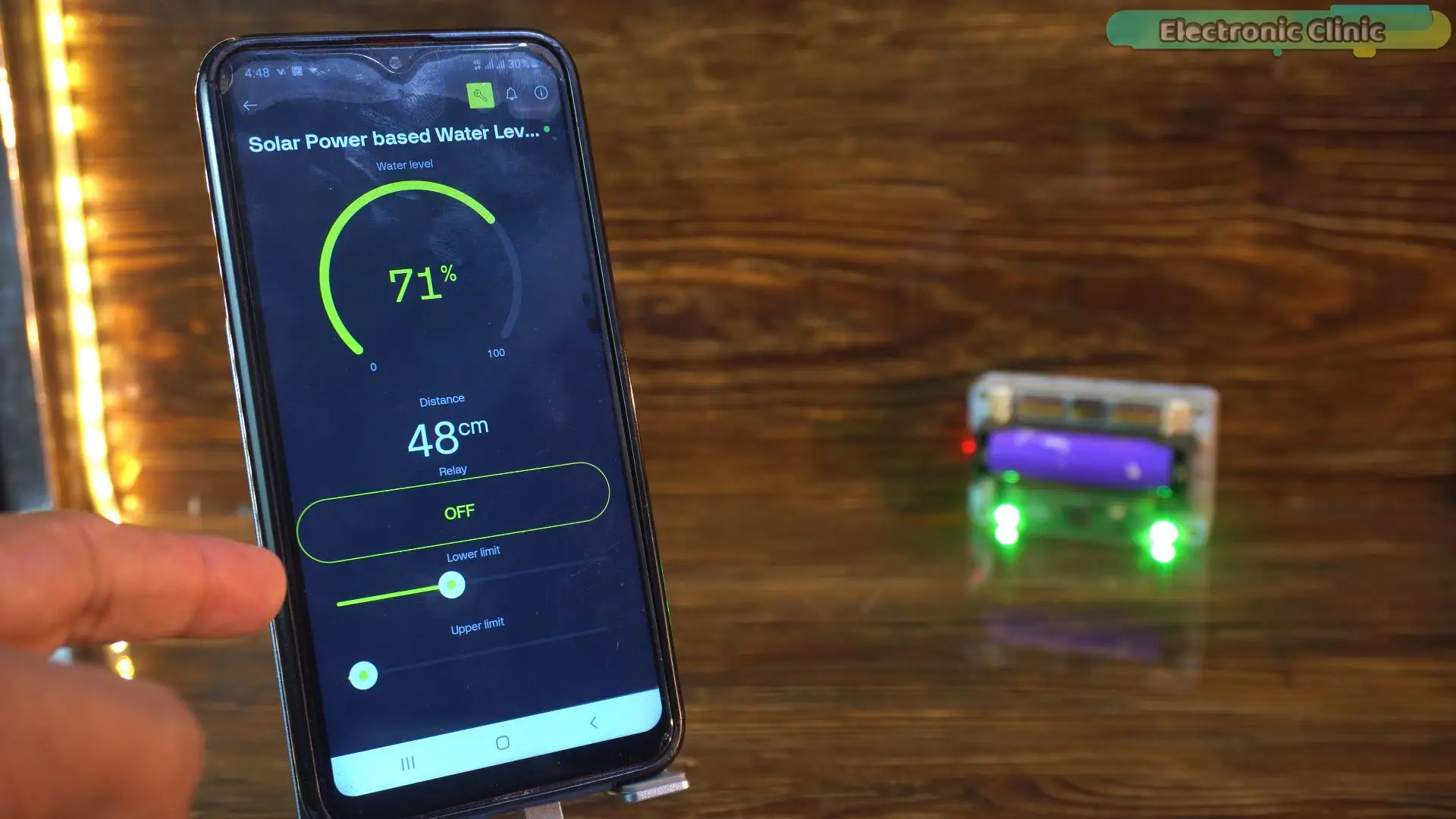
Right now, you can see the exact water percentage inside the tank in real time.
Now let’s test it properly. I am going to open the water taps and drain some water; and this is where things get interesting. Let’s see how fast and accurately this DIY solar-powered water tank level sensor responds.
A few moments later
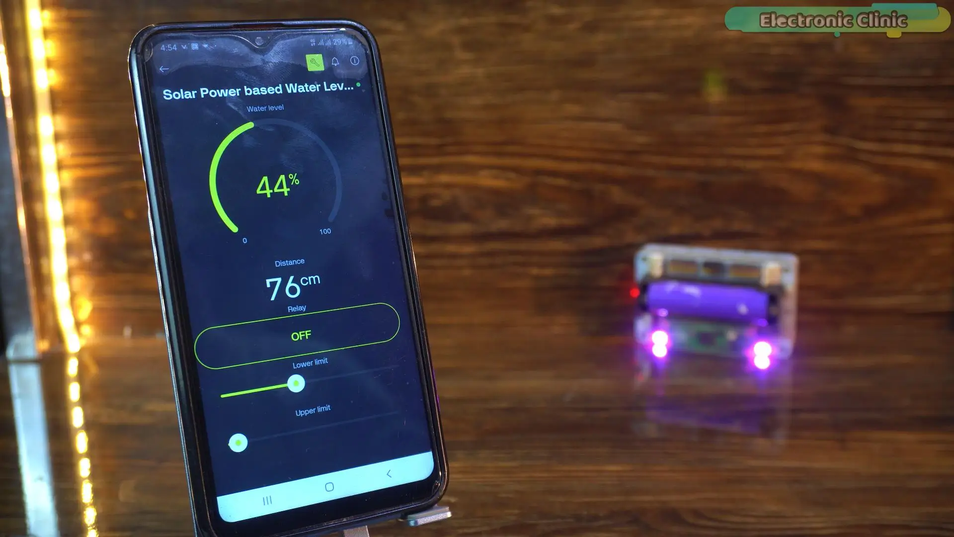
Look at that. The water level has dropped and the system detected it instantly.
Now obviously, I don’t want to completely empty the tank. So instead of waiting for the water pump to turn ON automatically, I am going to manually start the water pump using the control button.
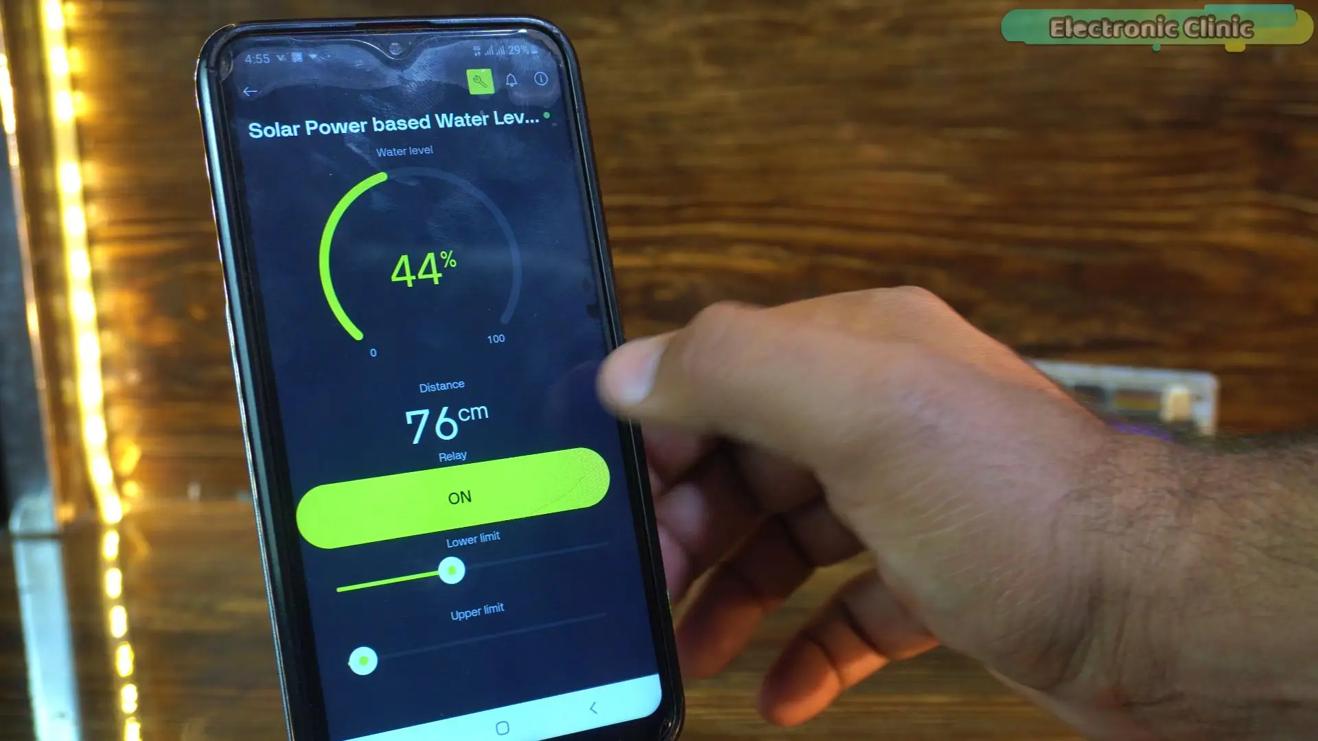
A few moments later…
And there you go.
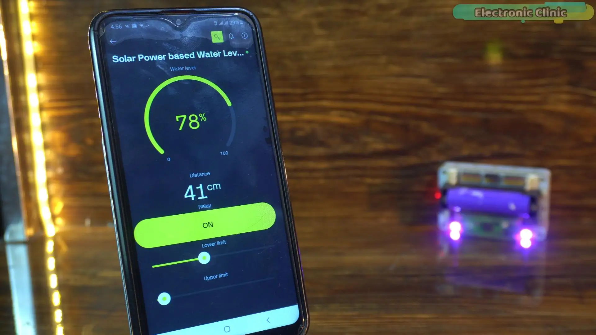
The water percentage is increasing again. Smooth, automatic, and fully controlled.
This is exactly how a smart solar-powered water tank monitoring system should work.
So, that’s all for now.
Support me on Patreon:
If you enjoy my work and find these projects helpful, please consider supporting me on Patreon. With just $1, you can get access to all project source codes, schematics, and extra resources that I share with my supporters. Your support helps me continue creating new electronics tutorials, experiments, and open projects for the community. Thank you so much for being part of this journey and for supporting my work!
Watch Video Tutorial:
Discover more from Electronic Clinic
Subscribe to get the latest posts sent to your email.